

Optical data coupler
DAD30-RT/35
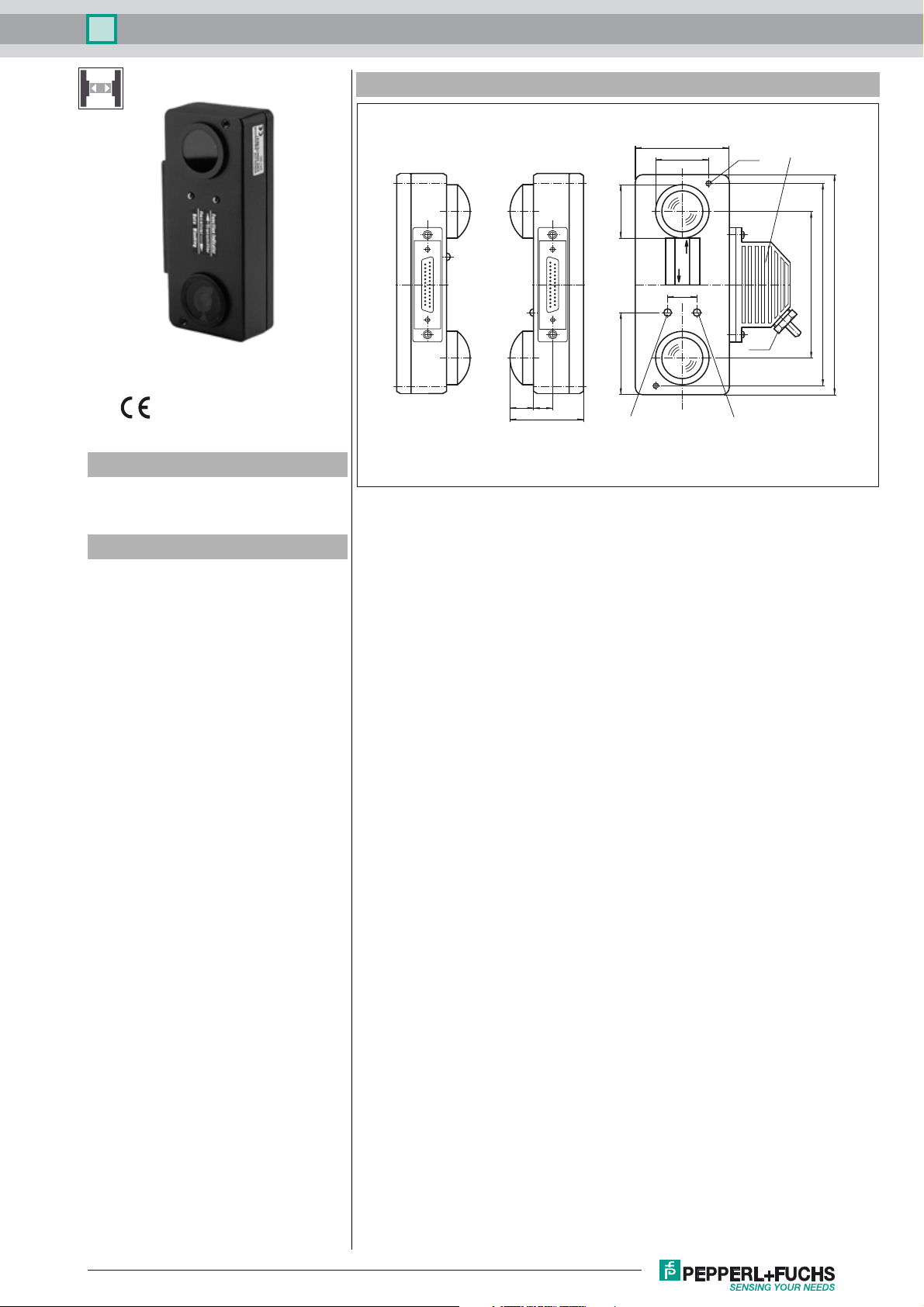
Dimensions
Model Number
DAD30-RT/35
Optical data coupler
Features
• Compact, flat aluminium housing
• 3 interfaces in a device can be selected via DIP switches
• Visible red light
• Mating connector with protective cover included delivery
View without connector
1
25
Emitter
Receiver
Receiver
Emitter
64
36
36.4
25
1
56
16
13
50
Function display
Emitter
Receiver
Function display
20
Data sampling blanking
LED-data sampling blanking
M4 (2 x)
Pg 7.5
Unit connector
VISOLUX
138
150
100
Release date: 2011-08-31 09:02 Date of issue: 2011-08-31 418450_eng.xml
Subject to modifications without notice
Copyright Pepperl+Fuchs
1
Optical data coupler
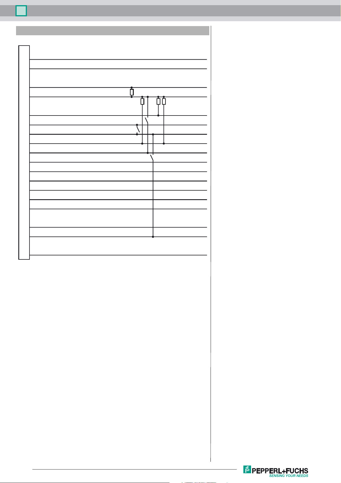
Electrical connection
Option:
DAD30-RT/35
2
3
6
7
9
10
11
12
13
14
15
16
17
18
19
RX232
TX232
Alarm 1
0 V
Analog
RX-DIS
+UB
Alarm 2
RX-DIS/TTL
RX-P
RX-N
TX-P
TX-N
CL-IN+
CL-IN-
RS 232 input
RS 232 output
(simple stability control)
Measuring output
Data sampling blanking
(sufficient stability control)
Data switch off
RS 422 (B-input)
RS 422 (A-input)
RS 422 (B-output)
RS 422 (A-output)
Current loop input
Current loop input
21
22
25
CL-OUT-
TX-DIS
CL-OUT+
Current loop output
Emitter deactivation
Current loop output
Subject to modifications without notice
2
Release date: 2011-08-31 09:02 Date of issue: 2011-08-31 418450_eng.xml
Copyright Pepperl+Fuchs

Optical data coupler
Technical data
General specifications
Effective detection range 0 ... 100 m
Threshold detection range 150 m
Light source LED
Light type modulated visible red light
Approvals CE
Alignment aid with function display
Transmission mode FSK
Response delay 40 µs
Diameter of the light spot 1800 mm at a distance of 100 m
Angle of divergence Emitter: 1 ° Receiver: 5 °
Ambient light limit 30000 Lux
Indicators/operating means
Function display LED red: switch point
Controls 8-fold DIP-switch for selection of transmission frequency and
Electrical specifications
Operating voltage UB24 V DC ± 25 %
No-load supply current I
Data sampling blanking Input for incoming data blanking with +24 V DC
Data rate 0 ... 19.2 kBit/s
Operation frequency F1 = 83 kHz F2 = 118 kHz
Interface
Interface type RS 232, RS 422, CL20 mA active/passive switchable
Output
Output of the pre-fault indication 2 PNP-outputs, short-circuit protected, 30 V DC 0.1 A
Measurement output +1.8 ... 5.8 V DC, max. 10 mA,
Standard conformity
Standards EN 60947-5-2
Ambient conditions
Ambient temperature -20 ... 60 °C (-4 ... 140 °F)
Storage temperature -20 ... 75 °C (-4 ... 167 °F)
Mechanical specifications
Protection degree IP65
Connection 25-pin Sub-D connector
Material
Housing aluminum
Optical face plastic lens
Mass 500 g
LED green: sufficient stability control
interface
200 mA
0
activated for single or sufficient stability control
simple stability control: 2.5 V triple stability control: 4.2 V
DAD30-RT/35
Curves/Diagrams
Characteristic response curve
Offset Y [mm]
450
400
350
300
250
200
150
100
50
0
0
51015
x
y
DAD30
20
25
30 35
Distance X [m]
Release date: 2011-08-31 09:02 Date of issue: 2011-08-31 418450_eng.xml
Subject to modifications without notice
Copyright Pepperl+Fuchs
3

Optical data coupler
DAD30-RT/35
Relative received light strength
Stability control
1000
100
10
3
1
0
10
x
20
30
40
DAD30
50
Distance X [m]
Function
The DAD 30 is a device for serial data transfer for data rates up to 19.2 kBaud and ranges up to 100 m. The device can also be
used without problems for data rates and effective operating distances below these values. The transmission is protocol-free.
If two full-duplex routes are to be installed in parallel, infrared should be selected for one route and visible emitter light for the
other.
Data transfer
In order to avoid mutual interference of the two transfer channels, emitter and receiver of a device are operated at different centre frequencies F1/F2. The frequency is adjusted with the S1 DIP switch..
S1: ON = emitter F1, receiver F2
OFF = emitter F2, receiver F1
LED functional display / functional reserve
A two-color LED is used as the functional and alignment control. It is lit and red if the level of the received signal is assured for
a simple transfer. If the LED is lit and green, sufficient functional reserve is present. The indicator is independent of the data
transfer.
Interface
The DAD30 contains a standard interface module for serial transfer. The data lines have to be connected to the corresponding
pins of the connector according to the desired interface. All output interfaces are controlled at the same time. To select the input
interface, the appropriate DIP switch S4-S6 should be moved to the ON position.
20-mA electrical circuit (CL)
S4: ON = data in, 20 mA current loop
Serial interface with defined current level (Low = 0 mA,
High = 20 mA) and for connection to an opposite station. It
transfers data on lines over lengths of up to 1 km. With the
DAD 30, the 20 mA interfaces can be operated in either active or passive mode.
For the selection the DIP switches S7 and S8 are used.
Example:
Active Passive
20 mA
+
20 mA
+
18
S8
18
19
212557
+
+
The interface, that feeds the current is designated as active.
Only one of the two communication partners can be active
(optical data coupler or control system). By means of the
DIP-switches S7 and S8 the DAD 30 can be operated with
active as well as with passive CL 20 mA interface. It is also
possible to operate one interface in the active mode and the
other one in the passive mode.
Subject to modifications without notice
4
Control
Copyright Pepperl+Fuchs
Optical barrier, passive
Release date: 2011-08-31 09:02 Date of issue: 2011-08-31 418450_eng.xml

Optical data coupler
DAD30-RT/35
S7: ON = input interface active, 20 mA current loop
OFF= input interface passive
S8: ON = output interface active, 20 mA current loop
OFF= output interface passive
RS 422
S5: ON = data in, RS 422
Serial voltage interface, suited for rapid transmission over great distances (up to 1.5 km). The logical states can be defined by
comparing voltages.
RS 232
S6: ON = data in, RS 232
Serial voltage interface (one or two data lines) with the normal levels in the PC periphery (low = 3 to 15V, high = -3 V to -15 V),
in reference to a common ground. It is designed for distances of up to 20 m in range and connection to an opposite station.
Caution! Only one of the switches S4–S6 should be turned on!
With either one S2 or S3 switch, it is possible to invert data signals for special applications.
S2 ON = input signal of the emitter, inverted
OFF = input signal of the emitter, not inverted
S3 ON = output signal of the receiver, inverted
OFF = output signal of the receiver, not inverted
When the light beam is interrupted, the light beam switch on the receiver side goes into pause status. This status is logically
high for non-inverted data lines, in other words for the RS 232 – 3 V ... 15 V interface, for the RS 422 interface, the difference
in level is under 3 V (A <
B) and for the CL-interface a conducting 20 mA electrical circuit.
All previously defined switching positions can be set with the programming switch (S1-S8), which is located on the print. The
programming switch is visible on the print after the housing cover has been removed.
Data blanking receiver
An additional input is available for blanking the received data. This input must be wired with high level (+24 V) to activate blanking. Blanked status is indicated by a red LED.
Connector bar:
1
25
Release date: 2011-08-31 09:02 Date of issue: 2011-08-31 418450_eng.xml
Subject to modifications without notice
S1 ... S8
ON
12345678
OFF
Copyright Pepperl+Fuchs
5
 Loading...