

Optical data coupler
DAD15-8P
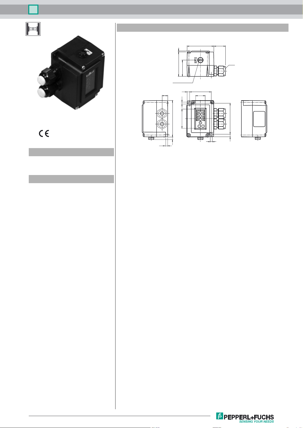
Dimensions
Model Number
DAD15-8P
Optical data coupler
Features
• 8 bit parallel data transfer
• Very large angle of divergence
• Can be connected in series
• Connection with spring-loaded terminals
• Degree of protection IP67
4.2
11.7
2
51
34
Sensitivity adjuster
5.5
4.3
76
40.2
5.8
56 24
45
20.1
4.3
M16
65
5.5
Release date: 2014-03-26 09:46 Date of issue: 2014-03-26 120838_eng.xml
Refer to “General Notes Relating to Pepperl+Fuchs Product Information”.
1
Optical data coupler
DAD15-8P
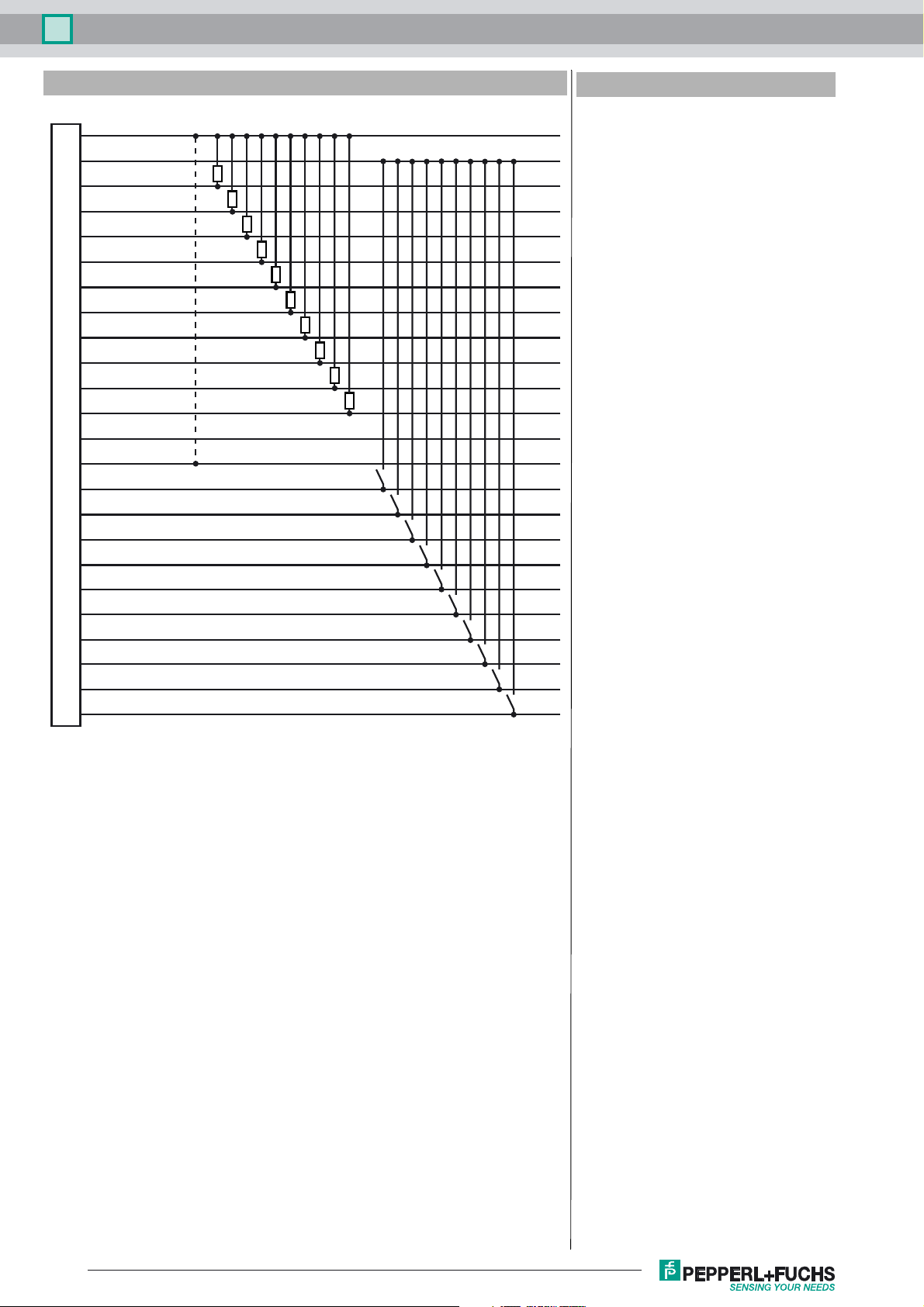
Electrical connection
0 V
1
+UB
2
SYNC
3
Reception indicator
4
D8OUT
5
D7OUT
6
D6OUT
7
D5OUT
8
D4OUT
9
D3OUT
10
D2OUT
11
D1OUT
12
n. c.
13
0V
14
D8IN
15
D7IN
16
D6IN
17
D5IN
18
D4IN
19
D3IN
20
D2IN
21
D1IN
22
IN Master/Slave
23
IN Enable
24
Accessories
OMH-DAD10
Mounting bracket
Refer to “General Notes Relating to Pepperl+Fuchs Product Information”.
2
Release date: 2014-03-26 09:46 Date of issue: 2014-03-26 120838_eng.xml

Optical data coupler
Technical data
General specifications
Effective detection range 0 ... 1500 mm
Threshold detection range 2500 mm
Light source IRED
Light type modulated infrared light
Diameter of the light spot approx. 1000 mm at 1.5 m
Angle of divergence ± 20 °
Ambient light limit 5000 Lux
Cycle time 35 ms
Functional safety related parameters
MTTFd 200 a
Mission Time (TM) 20 a
Diagnostic Coverage (DC) 0 %
Indicators/operating means
Operation indicator LED green
Data flow indicator Inputs: 8 LEDs green
Control elements sensitivity adjustment
Control elements Operating mode switch 4: Behavior when beam is broken
Electrical specifications
Operating voltage UB10 ... 60 V DC
No-load supply current I
Data sampling blanking Enable input emitter deactivation
Data rate 225 Bit/s
Interface
Interface type 8 bit parallel, bidirectional
Output
Switching voltage max. 60 V DC
Switching current max. 200 mA per channel , short-circuit protected , total ≤ 800
Ambient conditions
Ambient temperature -20 ... 60 °C (-4 ... 140 °F)
Storage temperature -20 ... 75 °C (-4 ... 167 °F)
Mechanical specifications
Degree of protection IP67
Connection 2 M16 cable glands, tension spring terminals in the terminal
Material
Housing Terluran, black
Optical face glass
Mass 170 g
Outputs: 8 LEDs red
Switches 1+2: Address
40 mA
0
10 inputs, PNP , 10 outputs, PNP
mA
compartment
DAD15-8P
Approvals and certificates
Approvals CE
Curves/Diagrams
Characteristic response curve
Offset Y [mm]
600
500
400
300
200
100
0
0123
x
y
DAD15
Distance X [m]
Release date: 2014-03-26 09:46 Date of issue: 2014-03-26 120838_eng.xml
Refer to “General Notes Relating to Pepperl+Fuchs Product Information”.
3

Optical data coupler
DAD15-8P
Relative received light strength
Stability control
100
10
3
1
012345
x
DAD15
Distance X [m]
Function
The DAD 15-8P can be used to transfer data words eight bits wide bidirectionally.
A device pair is required to set up a transmission route. One device is operated as the MASTER (high level on the Master/Slave
input) and the second one as the SLAVE (low level on the Master/Slave input).
All binary control signals present in parallel on inputs D1 - D8 are converted serially into an 8-bit sequence in the device, are
transferred over the light route and are again applied in parallel in the receiver to outputs D1 - D8. Interference-resistant PPM
modulation is used to transfer binary signals. The entire cycle during which the two current 8-bit words are transferred one after
the other in both directions, in the time multiplex procedure, lasts 35 ms. This corresponds to a data rate of 350 Baud. This time
multiplex procedure is of no significance to the user, since the last data to be received is stored and is available on the outputs
until the next change is made.
Output behaviour when the beam of light is interrupted
The behaviour of the data outputs when the light beam is broken can be adjusted with the aid of the 4 switch (data latch):
OFF: Data outputs are turned off when the light beam is broken.
ON: The last data to be received remains intact on the outputs when the light beam is broken.
Input/output / emitter deactivation
A high level on the ENABLE input is required to operate the DAD15-8P. If there is a low level on the ENABLE input, the emitter
will be turned off.
The ENABLE input has no function in SLAVE mode.
Inputs and outputs, reception indicator:
Receiver
Emitter
The states of data inputs and outputs are displayed individually via LEDs. A high level on the input is indicated by a green
LED. A red LED indicates an active output.
Correct reception is indicated with the output and the RE-
RxD
CEPTION INDICATOR LED.
The SYNC output indicates the end of a transmit or receive
cycle. Output data are valid with a falling edge and new input
data can be read.
Power-on
Refer to “General Notes Relating to Pepperl+Fuchs Product Information”.
4
Sensitivity adjuster
(behind the cover screw)
Release date: 2014-03-26 09:46 Date of issue: 2014-03-26 120838_eng.xml
Optical data coupler
DAD15-8P
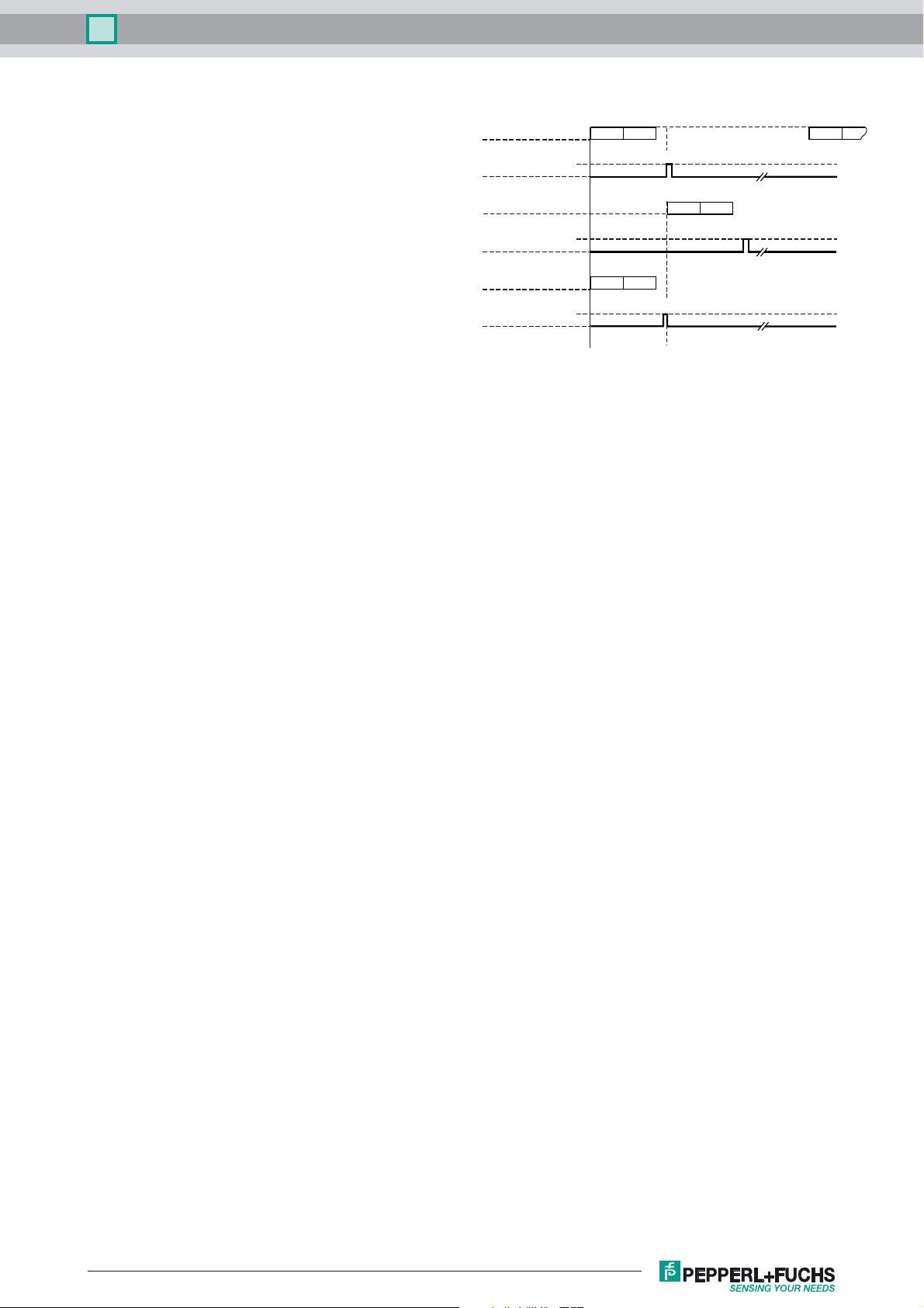
Chaining
The SYNC output can also be used to start an additional ENABLE input. Up to four MASTERS can be chained together
in this manner. The devices must then be addressed by
means of the A1 and A2 address switches. The SLAVE belonging to the MASTER in question requires the same
address switch setting.
Arrangement and mounting
The DAD15 data light barrier consists of an electronics unit
with spring-loaded terminals and 2 M16 cable glands.
The electronics unit is connected with an internal connector.
It is also fastened to it with 4 screws.
Accessories:
OMH-DAD10 mounting angle
Timing
Master 1
Sync. Master 1
Sync. Master 1
in
Enable Master 2
Master 2
Sync. Master 2
Slave 1
Sync. Slave 1
(for reception only)
3 ms 3 ms 35 ms
transmission
reception
transmission
0.5 ms
transmission
0.3 ms
reception
h
l
h
l
reception
h
l
transmission
recept
Release date: 2014-03-26 09:46 Date of issue: 2014-03-26 120838_eng.xml
Refer to “General Notes Relating to Pepperl+Fuchs Product Information”.
5
 Loading...