


Process indicator DA6-IU-2K-C
Technical data
General specifications
Pre-selection 2-fold
Data storage > 10 years, EEPROM
Programming keypad-driven menu
Indicators/operating means
Ty p e 14-segment LED display, red
Number of digits 6
Display value digit height 14 mm
Key interlock with "high"-level at terminal "KEY"
Model Number
DA6-IU-2K-C
Process control and indication equipment
Features
• 2 adjustable trip values
•2 relay outputs
• Operation via keypad
• Characteristic programmable via 12
interpolation points
• Resetting the outputs, automatic, manual or with external signal
• Connection via plug-in screw terminals
• Auxiliary power output for sensors
• Degree of protection IP65 in accordance with DIN EN 60529 (front only)
• Shock resistance in accordance with
DINEN60068-2-27
• Vibration resistance in accordance
with DIN EN 60068-2-6
• System hum suppression
Display interval -199999 ... 999999
Decimal point freely adjustable
Resolution 15 Bit
Scale factor via characteristic curve with up to 12 value pairs
Reset manually or external
Electrical specifications
Fusing T 0.4 A
Operating voltage U
Protection class IP65 (front)
Power consumption P
Input
Impedance > 1 MΩ for voltage measurement
Analog voltage input 0 ... 10 V / 2 ... 10 V DC,
Analog current input 0 ... 20 mA / 4 ... 20 mA
Output
Relay changeover contact
Switching voltage max. 250 V AC / 125 V DC
Switching current max. 5 A AC / 5 A DC
Switching power max. 1250 VA / 150 W
Sensor supply 15 V DC ± 1 %, 25 mA
Ambient conditions
Ambient temperature -10 ... 50 °C (14 ... 122 °F)
Storage temperature -20 ... 70 °C (-4 ... 158 °F)
Relative humidity ≤ 80 % (noncondensing)
Mechanical specifications
Connection 8-pin and 9-pin connectors with screw terminals
Mass 180 g
Dimensions 96 mm x 48 mm x 102 mm
Mounting mounting frame with latch fastener
Compliance with standards and directives
Directive conformity
EMC Directive 2004/108/EC EN 61000-6-2:2006
Standard conformity
Electrical isolation EN 61010-1:2010
Shock and impact resistance EN 60068-2-27:2009
Vibration resistance EN 60068-2-6:2008
with suppression of leading zeros
10 ... 30 V DC
B
3.8 W
0
22 Ω + PTC 25 Ω for current measurement
-10 ... 10 V DC
min. 5 V AC / 5 V DC
min. 10 mA DC
DIN EN 55011:2009, Class B
EN 60068-2-29:1995
Release date: 2015-04-16 16:41 Date of issue: 2015-04-16 248579_eng.xml
Refer to “General Notes Relating to Pepperl+Fuchs Product Information”.
1
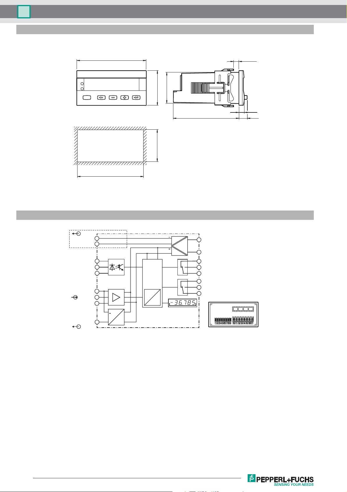
Dimensions
DA6-IU-2K-CProcess indicator
Electrical connection
24 VDC/30 mA
Control panel cutout
OUT
9
GND 3
8
MP-INP 2
MP-INP 1
IN
GND 2
GND 1
mA
VOLT
7
6
5
4
3
2
96
92 +0.8
AC version only
max. 35
48
43 x 90
7.35
90.5
11.2
45+0.6
DC version:
17
+
+
µC
A
+10 ... 30 VDC
AC version:
16
90 ... 260 VAC
15
14
Limit 1
13
12
11
Limit 2
10
OUT 1
OUT 2
D
Subject to modifications without notice
2
15 VDC/25 mA
OUT
+
1
Release date: 2015-04-16 16:41 Date of issue: 2015-04-16 248579_eng.xml
Copyright Pepperl+Fuchs
 Loading...