

Page 1

COMPACT MANUAL
CC-LINK GATEWAYS
FACTORY AUTOMATION
Page 2

CC-Link Gateways
With regard to the supply of products, the current issue of the following document is applicable: The
General Terms of Delivery for Products and Services of the Electrical Industry, published by the
Central Association of the Electrical Industry (Zentralverband Elektrotechnik und Elektroindustrie
(ZVEI) e.V.) in its most recent version as well as the supplementary clause: "Expanded reservation
of proprietorship".
Page 3

CC-Link Gateways
Table of contents
Table of contents
CC-Link Gateways
1 Introduction...........................................................................................5
2 Declaration of conformity....................................................................6
2.1 Declaration of conformity ............................................................................... 6
3 Safety.....................................................................................................7
3.1 Symbols relevant to safety ............................................................................. 7
3.2 General notes on safety.................................................................................. 7
3.3 Disposal............................................................................................................ 7
4 Setting up the AS-i bus........................................................................8
5 Configuration and Start-up of the Safety Monitor.............................9
6 Data transmission modes of the CC-Link Gateways.......................10
6.1 Standard mode............................................................................................... 11
6.1.1 Remote IO Points .......................................................................................................... 11
6.1.2 Buffer memory area ...................................................................................................... 13
6.1.3 Safety Status ............................ ... .. ................................ .. ... ............................... ... ......... 15
6.1.4 Fieldbus Bits.................................................................................................................. 15
6.1.5 Message Transmission.................................................................................................16
6.2 Compatibility mode for VBG-CCL-G4F........................................................17
6.2.1 Remote IO Points .......................................................................................................... 17
6.2.2 Buffer Memory Area...................................................................................................... 18
6.3 CC-Link V1 Mode ........................................................................................... 22
6.3.1 Remote IO Points .......................................................................................................... 22
6.3.2 Buffer Memory Area...................................................................................................... 23
6.4 Compatibility Mode for FX2N-32ASI-M ........................................................ 27
6.4.1 Remote IO Points .......................................................................................................... 27
6.4.2 Buffer Memory Area...................................................................................................... 27
6.5 Compatibility Mode for HK-ASICC ............................................................... 30
6.5.1 Remote IO Points .......................................................................................................... 30
6.5.2 Buffer Memory Area...................................................................................................... 30
7 Accessing command interface..........................................................31
7.1 Using BFM........... ........................................................................................... 31
7.2 Using "Message Transmission"................................................................... 34
02.05.2016
3
Page 4

CC-Link Gateways
Table of contents
8 Diagnostics.........................................................................................36
8.1 System diagnostics on the PC......................................................................36
8.1.1 Software for diagnostics, service and release measurements.................................36
8.1.2 AS-i Control Tools .........................................................................................................36
8.1.3 ASIMON ..........................................................................................................................36
8.1.4 Web server .....................................................................................................................36
8.2 Diagnostics on the host controller...............................................................37
8.2.1 Diagnostics through process data ......................................... ... ... .. ... ..........................37
8.2.1.1 Diagnosing the AS-i circuits..........................................................................................37
8.2.1.2 Diagnosing the Safety Monitor......................................................................................37
8.2.2 Diagnosing the safety unit using the command interface.........................................40
8.2.3 LEDs ...............................................................................................................................40
8.2.4 LC-Display......................................................................................................................40
8.2.5 AS-i Monitor ...................................................................................................................40
8.2.5.1 Duplicate address detection .........................................................................................40
8.2.5.2 Earth fault monitor ........................................................................................................41
8.2.5.3 Noise voltage detection ............................................................................................ ....41
8.2.5.4 Overvoltage detection...................................................................................................41
Flags + Fault Detector (see chap. 6.1.1). ............ .......................................................37
Safety diagnostics in the Input Data Image ................................ ................................37
Fieldbus Bits and Safety Status .................................................................................37
Safety diagnostics in the Input Data Image (IDI) 38
Safety diagnostics of safe AS-i inputs ........................................................................38
Safety diagnostics of safe AS-i outputs ......................................................................39
Changing the base setting ............................................................................ ..............40
9 Appendix.............................................................................................42
4
02.05.2016
Page 5
CC-Link Gateways
Introduction
1. Introduction
Congratulations
You have chosen a device manufactured by Pepperl+Fuchs. Pepperl+Fuchs develops, produces and distributes electronic sensors and interface modules for the
market of automation technology on a worldwide scale.
Before installing this equipment and put into operation, read this manual carefully.
This manual containes instructions and notes to help you through the installation
and commissioning step by step. This makes sure bring such a trouble-free use
of this product. This is for your benefit, since this:
• ensures the safe operation of the device
• helps you to exploit the full functionality of the device
• avoids errors and related malfunctions
• avoids costs by disruptions and any repairs
• increases the effectiveness and efficiency of your plant
Keep this manual at hand for subsequent operations on the device.
After opening the packaging please check the integrity of the device and the num-
ber of pieces of supplied.
Symbols used
The following symbols are used in this manual:
Information!
This symbol indicates important information.
Attention!
This symbol warns of a potential failure. Non-compliance may lead to interruptions of
the device, the connected peripheral systems, or plant, potentially leading to total malfunctioning.
Warning!
This symbol warns of an imminent danger. Non-compliance may lead to personal injuries that could be fatal or result in material damage s and destruction.
Contact
If you have any questions about the device, its functions, or accessories, please
contact us at:
Pepperl+Fuchs GmbH
Lilienthalstraße 200
68307 Mannheim
Telephone: +49 621 776-4411
Fax: +49 621 776-274411
E-Mail: fa-info@pepperl-fuchs.com
02.05.2016
5
Page 6

CC-Link Gateways
Declaration of conformity
2. Declaration of conformity
2.1 Declaration of conformity
This product was developed and manufactured under observance of the applicable European standards and guidelines.
Information!
A Declaration of Conformity can be requested from the manufacturer.
The product manufacturer, Pepperl+Fuchs GmbH, D-68307 Mannheim, has a
certified quality assurance system that conforms to ISO 9001.
6
02.05.2016
Page 7
CC-Link Gateways
Safety
3. Safety
3.1 Symbols relevant to safety
Information!
This symbol indicates important information.
Attention!
This symbol warns of a potential failure. Non-compliance may lead to interruptions of
the device, the connected peripheral systems, or plant, potentially leading to total malfunctioning.
Warning!
This symbol warns of an imminent danger. Non-compliance may lead to personal injuries that could be fatal or result in material damage s and destruction.
3.2 General notes on safety
Only instructed specialist staff may operate the device in accordance with the operating manual.
User modification and or repair are dangerous and will void the warranty and exclude the manufacturer from any liability. If serious fault s occur, stop using the device. Secure the device against inadvertent operation. In the event of repairs, return the device to your local Pepperl+Fuchs representative or sales office.
The connection of the device and maintenance work when live may only be carried out by a qualified electrical specialist.
The operating company bears responsibility for observing locally applicable safety regulations.
Store the not used device in the original packaging. This offers the device optimal
protection against impact and moisture.
Ensure that the ambient conditions comply with regulations.
3.3 Disposal
Information!
Electronic waste is hazardous waste. Please comply with all local ordinances when
disposing this product!
The device does not contain batteries that need to be removed before disposing it.
02.05.2016
7
Page 8

CC-Link Gateways
Setting up the AS-i bus
4. Setting up the AS-i bus
1. Connect the unit to power.
2. Connect the AS-i cable to the unit.
3. One after the other connect the AS-i slaves to the AS-i cable and set the
slave addresses.
You may set the addresses directly on the slave using a portable addresser
or by using the option [SLAVE ADR TOOL] in the display menu of your
gateway.
4. In the display menu select [QUICK SETUP] to use the configuration of all
AS-i circuits connected to the unit.
Confirm with [STORE+RUN].
5. Set the CC-Link address and connect the gateway to the host fieldbus controller.
You can set the addresses directly using the option [CC-LINK] in the display menu of your gateway or through the PC using the ASIMON software
with integrated AS-i Control Tools.
For more detailed information pleas e refer to the installation guide for your g ateway
which is included with the unit.
8
02.05.2016
Page 9
CC-Link Gateways
Configuration and Start-up of the Safety Monitor
5. Configuration and Start-up of the Safety Monitor
Configuration and start-up of the AS-i Safety Monitor is accomplished using a PC/
notebook running the ASIMON configuration software.
Note!
For more detailed information please refer to the separate manual for the ASIMON
configuration software.
Configuration should be performed only by a safety specialist. All safety-related
commands are password protected.
The correct safety functioning of the unit must absolutely be verified in the system!
Note!
Quick Start Guides for commis sionin g and ser vice are p rovide d on the w ebsite av ailable for download.
02.05.2016
9
Page 10
CC-Link Gateways
Data transmission modes of the CC-Link Gateways
6. Data transmission modes of the CC-Link Gateways
There are several modes for the transmission of data in CC-Link:
1. Standard mode (see chap. 6.1)
2. Compatibility mode for VBG-CCL-G4F COMP (see chap. 6.2)
3. Compatibility mode for CC-Link V1 (see chap. 6.3)
4. Compatibility mode for FX2N-32ASI-M CP (see chap. 6.4)
5. Compatibility mode for HK-ASICC COMP (see chap. 6.5)
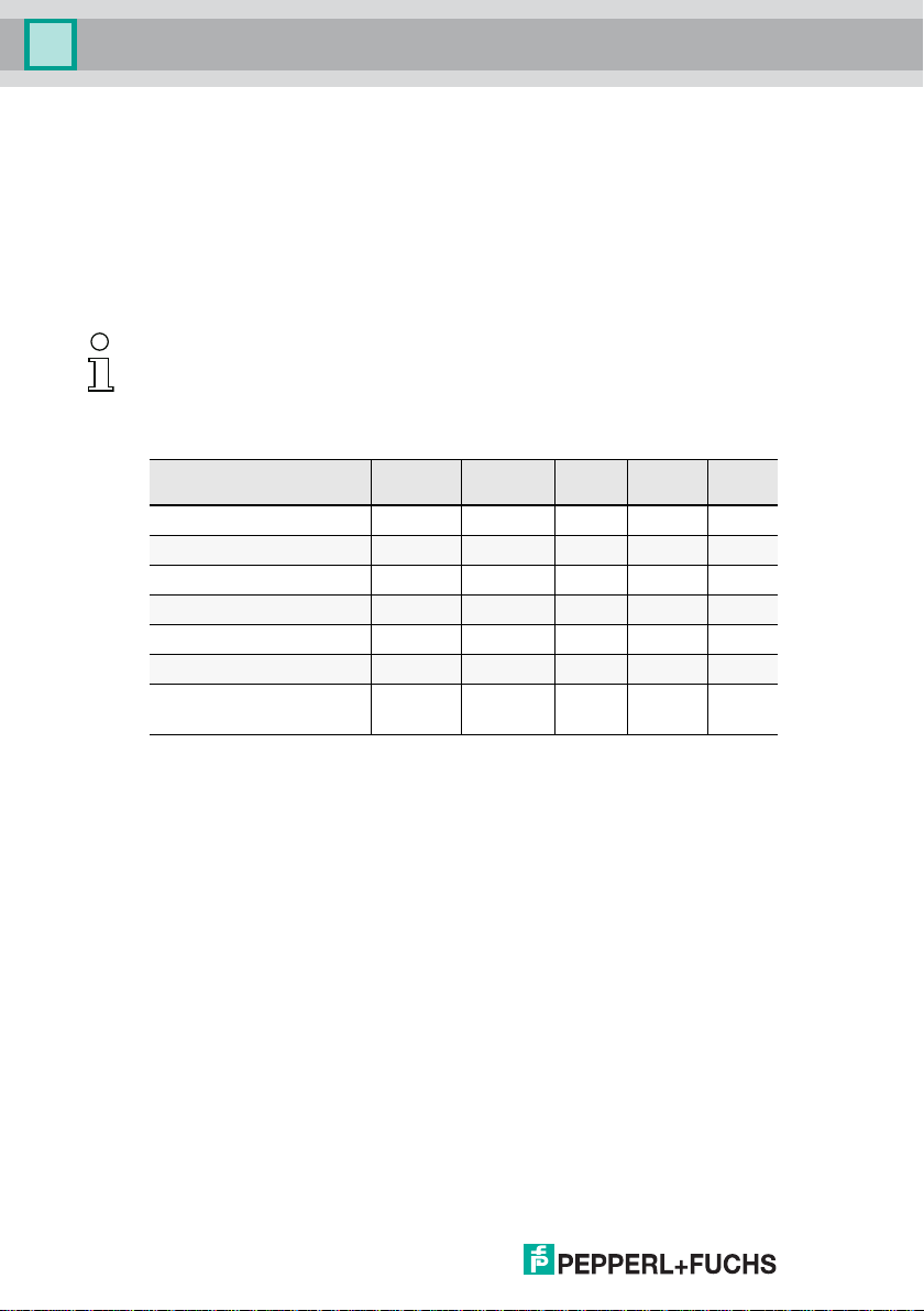
Information!
The selection of each data tr ansmi ss ion mod e take s plac e i n the me nu of t he g at ew ay
using the buttons and the display. Addi tional information ca n be foand in the description of the display menu of your gateway.
Summary of data transmission modes
Standard
occupied stations 3 3 4 4 2
cycle setting 2 1 1 1 1
required CC-Link master V2 V1 V1 V1 V1
support of 2 AS-i circuits no no no no no
support of B-slaves yes (yes) yes no no
support of analog slaves yes yes yes no no
support of AS-i configurati o n
via CC-Link
yes yes yes no no
VBG-CCL-
G4F
CC-Link V1FX2N-
32ASI-M
HK-
ASICC
Tab. 6-1.
10
02.05.2016
Page 11
CC-Link Gateways
Data transmission modes of the CC-Link Gateways
6.1 Standard mode
The Standard Mode has the following features:
• the gateway occupies 3 stations and has a double cycle setting.
• The last 2 words are reserved for "Message Transmission".
• The AS-i process data is mapped into the Buffer Memory Area (BFM).
• All acyclic requests are handled by "Message Transmission" using cyclic
data.
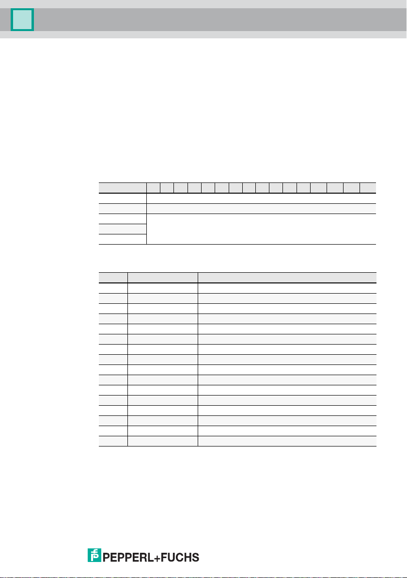
6.1.1 Remote IO Points
Remote to Host
Address 15 14 13 12 11 10 9 8 7 6 5 4 3 2 1 0
RXm reserved
RXm+1 AS-i circuit 1: EC-Flags and Fault Detector
RXm+2
RXm+9
EC-Flags and Fault Detector
Bit Short Cut Name
0 Cfg. OK Configuration OK
1 S0 Slave Address 0 detected
2 Aaasn Auto Address Assign
3 Aaavail Auto Address Available
4 CM Configuration Mode active
5 NA Normal Operation active
6 APF AS-i Power Fail (AS-i voltage below 19 V)
7 Offl Off-line
8 NPF No Peripheral Fault
9 reserved reserved
10 PWRw Power Warning (AS-i voltage below 22.5 V)
11 reserved reserved
12 EF Earth Fault
13 OV Over-voltage on AS-i
14 Noise Noise
15 reserved reserved
reserved…
Tab. 6-2.
Tab. 6-3.
02.05.2016
11
Page 12

CC-Link Gateways
Data transmission modes of the CC-Link Gateways
Host to Remote
Address 15 14 13 12 11 10 9 8 7 6 5 4 3 2 1 0
RYm PM CM AAE OFL
RYm+1 reserved
…
RYm+9
Tab. 6-4.
Flags in RYm
Bit Short Cut Name
0 OFL Offline
1 AAE Auto Address Enable
2 CM Enter Configuration Mode on rising edge
3 PM Enter Protected Mode on rising edge
4 … 15 reserved
Tab. 6-5.
12
02.05.2016
Page 13

CC-Link Gateways
Data transmission modes of the CC-Link Gateways
6.1.2 Buffer memory area
Buffer memory
for master without integr. safety monitor
Address 1 Master
0 … 7 AS-i 1, input A + single slaves AS-i 1, output A + single slaves
8 … 15 AS-i 1, input B slaves AS-i 1, output B slaves
16 … 23 reserved
Buffer memory (read)
for master with integr. safety monitor
Address Bit 15 … 12 Bit 11 … 8 Bit 7 … 4 Bit 3 … 0
RWrm0 AS-i 1: Inp. Slv3 AS-i 1: Inp. Slv2 AS-i 1: Inp. Slv1 flags AS-i 1
RWrm1 AS-i 1: Inp. Slv7 AS-i 1: Inp. Slv6 AS-i 1: Inp. Slv5 AS-i 1: Inp. Slv4
RWrm2 AS-i 1: Inp. Slv11 AS-i 1: Inp. Slv10 AS-i 1: Inp. Slv9 AS-i 1: Inp. Slv8
RWrm3 AS-i 1: Inp. Slv15 AS-i 1: Inp. Slv14 AS-i 1: Inp. Slv13 AS-i 1: Inp. Slv12
RWrm4 AS-i 1: Inp. Slv19 AS-i 1: Inp. Slv18 AS-i 1: Inp. Slv17 AS-i 1: Inp. Slv16
RWrm5 AS-i 1: Inp. Slv23 AS-i 1: Inp. Slv22 AS-i 1: Inp. Slv21 AS-i 1: Inp. Slv20
RWrm6 AS-i 1: Inp. Slv27 AS-i 1: Inp. Slv26 AS-i 1: Inp. Slv25 AS-i 1: Inp. Slv24
RWrm7 AS-i 1: Inp. Slv31 AS-i 1: Inp. Slv30 AS-i 1: Inp. Slv29 AS-i 1: Inp. Slv28
RWrm8 AS-i 1: Inp. Slv3B AS-i 1: Inp. Slv2B AS-i 1: Inp. Slv1B
RWrm9 AS-i 1: Inp. Slv7B AS-i 1: Inp. Sl v6B AS-i 1: Inp. Slv5B AS-i 1: Inp. Slv4B
RWrm10 AS-i 1:
Inp. Slv11B
RWrm11 AS-i 1:
Inp. Slv15B
RWrm12 AS-i 1:
Inp. Slv19B
RWrm13 AS-i 1:
Inp. Slv23B
RWrm14 AS-i 1: Inp.
Slv27B
RWrm15 AS-i 1:
Inp. Slv31B
RWrm16 fieldbus bits 15 … 8 fieldbus bits 7 … 0
RWrm17 Safety Status OSSD2 Safety Status OSSD1
RWrm18 Safety Status OSSD4 Safety Status OSSD3
RWrm19 Safety Status OSSD6 Safety Status OSSD5
read write
AS-i 1:
Inp. Slv10B
AS-i 1:
Inp. Slv14B
AS-i 1:
Inp. Slv18B
AS-i 1:
Inp. Slv22B
AS-i 1: Inp.
Slv26B
AS-i 1:
Inp. Slv30B
AS-i 1:
Inp. Slv9B
AS-i 1:
Inp. Slv13B
AS-i 1:
Inp. Slv17B
AS-i 1:
Inp. Slv21B
AS-i 1: Inp.
Slv25B
AS-i 1:
Inp. Slv29B
Tab. 6-6.
AS-i 1:
Inp. Slv8B
AS-i 1:
Inp. Slv12B
AS-i 1:
Inp. Slv16B
AS-i 1:
Inp. Slv20B
AS-i 1: Inp.
Slv24B
AS-i 1:
Inp. Slv28B
Tab. 6-7.
02.05.2016
13
Page 14

CC-Link Gateways
Data transmission modes of the CC-Link Gateways
Bits in flags
Bit Name
0 0: No C onfig Error
1 0: AS-i Power OK
2 0: Normal Operation active
3 0: Protected Mode active
Tab. 6-8.
Buffer memory (write)
for master with integr. safety monitor
Address Bit 15 … 12 Bit 11 … 8 Bit 7 … 4 Bit 3 … 0
RWwm0 AS-i 1: Outp. Slv3 AS-i 1: Outp. Slv2 AS-i 1: Outp. Slv1
RWwm1 AS-i 1: Outp. Slv7 AS-i 1: Outp. Slv6 AS-i 1: Outp. Slv5 AS-i 1: Outp. Slv4
RWwm2 AS-i 1: Outp.
Slv11
RWwm3 AS-i 1:
Outp. Slv15
RWwm4 AS-i 1:
Outp. Slv19
RWwm5 AS-i 1:
Outp. Slv23
RWwm6 AS-i 1:
Outp. Slv27
RWwm7 AS-i 1:
Outp. Slv31
RWwm8 AS-i 1:
Outp. Slv3B
RWwm9 AS-i 1:
Outp. Slv7B
RWwm10 AS-i 1:
Outp. Slv11B
RWwm11 AS-i 1:
Outp. Slv15B
RWwm12 AS-i 1:
Outp. Slv19B
RWwm13 AS-i 1:
Outp. Slv23B
RWwm14 AS-i 1:
Outp. Slv27B
RWwm15 AS-i 1:
Outp. Slv31B
AS-i 1:
Outp. Slv10
AS-i 1:
Outp. Slv14
AS-i 1:
Outp. Slv18
AS-i 1:
Outp. Slv22
AS-i 1:
Outp. Slv26
AS-i 1:
Outp. Slv30
AS-i 1:
Outp. Slv2B
AS-i 1:
Outp. Slv6B
AS-i 1:
Outp. Slv10B
AS-i 1:
Outp. Slv14B
AS-i 1:
Outp. Slv18B
AS-i 1:
Outp. Slv22B
AS-i 1:
Outp. Slv26B
AS-i 1:
Outp. Slv30B
AS-i 1:
Outp. Slv9
AS-i 1:
Outp. Slv13
AS-i 1:
Outp. Slv17
AS-i 1:
Outp. Slv21
AS-i 1:
Outp. Slv25
AS-i 1:
Outp. Slv29
AS-i 1:
Outp. Slv1B
AS-i 1:
Outp. Slv5B
AS-i 1:
Outp. Slv9B
AS-i 1:
Outp. Slv13B
AS-i 1:
Outp. Slv17B
AS-i 1:
Outp. Slv21B
AS-i 1:
Outp. Slv25B
AS-i 1:
Outp. Slv29B
AS-i 1:
Outp. Slv8
AS-i 1:
Outp. Slv12
AS-i 1:
Outp. Slv16
AS-i 1:
Outp. Slv20
AS-i 1:
Outp. Slv24
AS-i 1:
Outp. Slv28
AS-i 1:
Outp. Slv4B
AS-i 1:
Outp. Slv8B
AS-i 1:
Outp. Slv12B
AS-i 1:
Outp. Slv16B
AS-i 1:
Outp. Slv20B
AS-i 1:
Outp. Slv24B
AS-i 1:
Outp. Slv28B
RWwm16 fieldbus bits 15 … 8 fieldbus bits 7 … 0
…
RWwm19
reserved
Tab. 6-9.
14
02.05.2016
Page 15

CC-Link Gateways
Data transmission modes of the CC-Link Gateways
Bits in flags
Bit Name
0 0: No C onfig Error
1 0: AS-i Power OK
2 0. Normal Operation active
3 0: Protected Mode active
6.1.3 Safety Status
Tab. 6-10.
Bits in Safety Status
Bit
7
2
one or more
devices are red
flashing
6
2
one or more
devices are yellow
flashing
6.1.4 Fieldbus Bits
Information!
This functionality is only available in devices in t he safety ve rsion ’SV 4.3’ (see latera l
label)!
The fieldbus bits enable communication between the controller and the safety
program. The fieldbus bits can be used to pass any acknowledgment signals or
similar to the safety program and provide status information to the controller.
The states of the AS-i Safety in- and outputs are sent to the controller via the input data image (see par. <Safety diagnostics in the Input Data Image (IDI)>).
Output data (device fieldbus bit in ASIMON)
2152142132122112102928272625242322212
FB15FB14FB13FB12FB11FB10FB09FB08FB07FB06FB05FB04SI 4SI 3SI 2SI 1
Input data (output assignment fieldbus bit in ASIMON)
2152142132122112102928272625242322212
FB15FB14FB13FB12FB11FB10FB09FB08FB07FB06FB05FB04FB03FB02FB01FB
FB: fieldbus bit
SI1 … SI4: monitor inputs
02.05.2016
25242322212
OSSD Color
0: green
1: flashing green
2: yellow
reserved
3: yellow flashing
4: red
5: flashing red
6: grey
7: reserved
Tab. 6-11. Bits in Safety Status
Tab. 6-12.
Tab. 6-13.
0
0
0
00
15
Page 16

CC-Link Gateways
Data transmission modes of the CC-Link Gateways
Information!
More detailed information can b e found in the manual "ASIMON configuration software", sections: "Monitoring devices -> Fieldbus bit" and "Output assignment"..
6.1.5 Message Transmission
"Message Transmission" provides only command interface commands (see separate manual "AS-i 3.0 Command Interface").
Information!
For details on the Message Tran smiss io n pr ot oc ol, plea se re fer to the CC- Link sp ec ifi cation. For more informat ion or PLC program examples, how to u se Message Transmission, please refer to the documentatio n of your CC-Link master in use.
16
02.05.2016
Page 17

CC-Link Gateways
Data transmission modes of the CC-Link Gateways
6.2 Compatibility mode for VBG-CCL-G4F
The Compatibility Mode for VBG-CCL-G4F has the following features:
• 3 stations are occupied using a single cycle setting.
• All functions of VBG-CCL-G4F are implemented.
• The AS-i process data or the command interface is mapped into the buffer
memory area (BFM) (as done in the VBG-CCL-G4F).
• "Message Transmission" is not supported
(since VBG-CCL-G4F also does not use it).
6.2.1 Remote IO Points
Remote to Host
Address 15 14 13 12 11 10 9 8 7 6 5 4 3 2 1 0
RXm reserved BfEAck MbAck reserved
RXm+1
…
RXm+5
Flags in RXm
Bit Short Cut Name
0 … 3 reserved
4 MbAck Acknowledge bit for Y4
5 BfEAck Acknowledge bit for Y5
6 … 15 reserved
Host to Remote
Address 15 14 13 12 11 10 9 8 7 6 5 4 3 2 1 0
RYm reserved BfE Mb PM CM AAE OFL
RYm+1
…
RYm+5
reserved
Tab. 6-14.
Tab. 6-15.
reserved
Tab. 6-16.
02.05.2016
17
Page 18

CC-Link Gateways
Data transmission modes of the CC-Link Gateways
Flags in RYm
Bit Short Cut Name
0 OFL Offline
1 AAE Auto Address Enable
2 CM Enter Configuration Mode on rising edge
3 PM Enter Protected Mode on rising edge
4 Mb 0: BFM used for IO data onl y
5 BfE 0: Enable use of BFM
6 … 15 reserved
6.2.2 Buffer Memory Area
Buffer memory (read) when using ’IO data only mode’
Address Bit 15 … 12 Bit 11 … 8 Bit 7 … 4 Bit 3 … 0
RWrm0
RWrm1
RWrm2
RWrm3
RWrm4
RWrm5
RWrm6
RWrm7
RWrm8
RWrm9
RWrm10
RWrm11
AS-i 1: Inp. Slv3 AS-i 1: Inp. Slv2 AS-i 1: Inp. Slv1 flags
AS-i 1: Inp. Slv7 AS-i 1: Inp. Slv6 AS-i 1: Inp. Sl v5 AS-i 1: Inp. Slv4
AS-i 1:
Inp. Slv11
AS-i 1:
Inp. Slv15
AS-i 1:
Inp. Slv19
AS-i 1:
Inp. Slv23
AS-i 1:
Inp. Slv27
AS-i 1:
Inp. Slv31
AS-i 1:
Inp. Slv3B
AS-i 1:
Inp. Slv7B
AS-i 1:
Inp. Slv11B
AS-i 1:
Inp. Slv15B
1: BFM used for command interface
Tab. 6-17.
AS-i 1:
Inp. Slv10
AS-i 1:
Inp. Slv14
AS-i 1:
Inp. Slv9
AS-i 1:
Inp. Slv13
AS-i 1:
Inp. Slv8
AS-i 1:
Inp. Slv12
AS-i 1: Inp. Slv18 AS-i 1: Inp. Slv17 AS-i 1: Inp. Slv16
AS-i 1:
Inp. Slv22
AS-i 1:
Inp. Slv26
AS-i 1:
Inp. Slv30
AS-i 1:
Inp. Slv2B
AS-i 1:
Inp. Slv6B
AS-i 1:
Inp. Slv10B
AS-i 1:
Inp. Slv14B
AS-i 1:
Inp. Slv21
AS-i 1:
Inp. Slv25
AS-i 1:
Inp. Slv29
AS-i 1:
Inp. Slv1B
AS-i 1:
Inp. Slv5B
AS-i 1:
Inp. Slv9B
AS-i 1:
Inp. Slv13B
AS-i 1:
Inp. Slv20
AS-i 1:
Inp. Slv24
AS-i 1:
Inp. Slv28
AS-i 1:
Inp. Slv4B
AS-i 1:
Inp. Slv8B
AS-i 1:
Inp. Slv12B
Tab. 6-18.
Bits in Flags
Bit Name
0 0: No C onfig Error
1 0: AS-i Power OK
2 0. Normal Operation active
3 0: Protected Mode active
18
Tab. 6-19.
02.05.2016
Page 19

CC-Link Gateways
Data transmission modes of the CC-Link Gateways
Buffer memory (read) when using ’command interface mode’
Address Bit 15 … 12 Bit 11 … 8 Bit 7 … 4 Bit 3 … 0
RWrm0
RWrm1
RWrm2
RWrm3
RWrm4
RWrm5
RWrm6
RWrm7
RWrm8
RWrm9
RWrm10
RWrm11
command interface:
circuit
command interface:
response byte 2
command interface:
response byte 4
command interface:
response byte 6
command interface:
response byte 8
command interface:
response byte 10
command interface:
response byte 12
command interface:
response byte 14
command interface:
response byte 16
command interface:
response byte 18
command interface:
response byte 20
command interface:
response byte 22
command interface:
command
command interface:
response byte 1
command interface:
response byte 3
command interface:
response byte 5
command interface:
response byte 7
command interface:
response byte 9
command interface:
response byte 11
command interface:
response byte 13
command interface:
response byte 15
command interface:
response byte 17
command interface:
response byte 19
command interface:
response byte 21
Tab. 6-20.
02.05.2016
19
Page 20

CC-Link Gateways
Data transmission modes of the CC-Link Gateways
Buffer memory (write) when using ’IO data only mode’
Address Bit 15 … 12 Bit 11 … 8 Bit 7 … 4 Bit 3 … 0
RWwm0
RWwm1
RWwm2
RWwm3
RWwm4
RWwm5
RWwm6
RWwm7
RWwm8
RWwm9
RWwm10
RWwm11
AS-i 1:
Outp. Slv3
AS-i 1:
Outp. Slv7
AS-i 1:
Outp. Slv11
AS-i 1:
Outp. Slv15
AS-i 1:
Outp. Slv19
AS-i 1:
Outp. Slv23
AS-i 1:
Outp. Slv27
AS-i 1:
Outp. Slv31
AS-i 1:
Outp. Slv3B
AS-i 1:
Outp. Slv7B
AS-i 1:
Outp. Slv11B
AS-i 1:
Outp. Slv15B
AS-i 1:
Outp. Slv2
AS-i 1:
Outp. Slv6
AS-i 1:
Outp. Slv10
AS-i 1:
Outp. Slv14
AS-i 1:
Outp. Slv18
AS-i 1:
Outp. Slv22
AS-i 1:
Outp. Slv26
AS-i 1:
Outp. Slv30
AS-i 1:
Outp. Slv2B
AS-i 1:
Outp. Slv6B
AS-i 1: Outp.
Slv10B
AS-i 1:
Outp. Slv14B
AS-i 1:
Outp. Slv1
AS-i 1:
Outp. Slv5
AS-i 1:
Outp. Slv9
AS-i 1:
Outp. Slv13
AS-i 1:
Outp. Slv17
AS-i 1:
Outp. Slv21
AS-i 1:
Outp. Slv25
AS-i 1:
Outp. Slv29
AS-i 1:
Outp. Slv1B
AS-i 1:
Outp. Slv5B
AS-i 1: Outp.
Slv9B
AS-i 1:
Outp. Slv13B
flags
AS-i 1:
Outp. Slv4
AS-i 1:
Outp. Slv8
AS-i 1:
Outp. Slv12
AS-i 1:
Outp. Slv16
AS-i 1:
Outp. Slv20
AS-i 1:
Outp. Slv24
AS-i 1:
Outp. Slv28
AS-i 1:
Outp. Slv4B
AS-i 1: Outp.
Slv8B
AS-i 1:
Outp. Slv12B
Tab. 6-21.
20
02.05.2016
Page 21

CC-Link Gateways
Data transmission modes of the CC-Link Gateways
Buffer memory (write) when using ’command interface mode’
Address Bit 15 … 12 Bit 11 … 8 Bit 7 … 4 Bit 3 … 0
RWwm0
RWwm1
RWwm2
RWwm3
RWwm4
RWwm5
RWwm6
RWwm7
RWwm8
RWWm9
RWwm10
RWwm11
command interface:
circuit
command interface:
request byte 2
command interface:
request byte 4
command interface:
request byte 6
command interface:
request byte 8
command interface:
request byte 10
command interface:
request byte 12
command interface:
request byte 14
command interface:
request byte 16
command interface:
request byte 18
command interface:
request byte 20
command interface:
request byte 22
command interface:
command
command interface:
request byte 1
command interface:
request byte 3
command interface:
request byte 5
command interface:
request byte 7
command interface:
request byte 9
command interface:
request byte 11
command interface:
request byte 13
command interface:
request byte 15
command interface:
request byte 17
command interface:
request byte 19
command interface:
request byte 21
Tab. 6-22.
02.05.2016
21
Page 22

CC-Link Gateways
Data transmission modes of the CC-Link Gateways
6.3 CC-Link V1 Mode
CC-Link V1 Mode is an enxanced version of the compatibility mode for VBG-
CCL-G4F.
Features:
• 4 stations are occupied using a single cycle setting.
• The AS-i process data or the mailbox is mapped into the buffer memory area
(BFM) (as done in the VBG-CCL-G4F).
• "Message Transmission" is not supported.
6.3.1 Remote IO Points
Remote to Host
Address 15 14 13 12 11 10 9 8 7 6 5 4 3 2 1 0
RXm reserved BfEAck MbAck reserved
RXm+1
…
RXm+7
Flags in RXm
Bit Short Cut Name
0 … 3 reserved
4 MbAck Acknowledge bit for Y4
5 BfEAck Acknowledge bit for Y5
6 … 15 reserved
Host to Remote
Address 15 14 13 12 11 10 9 8 7 6 5 4 3 2 1 0
RYm reserved BfE Mb PM CM AAE OFL
RYm+1
…
RYm+7
reserved
Tab. 6-23.
Tab. 6-24.
reserved
Tab. 6-25.
Flags in RYm
Bit Short Cut Name
0 OFL Offline
1 AAE Auto Address Enable
2 CM Enter Configuration Mode on rising edge
3 PM Enter Protected Mode on rising edge
4 Mb 0: BFM used for IO Data only
5 BfE 0: Enable use of BFM
6 … 15 reserved
22
1: BFM used for command interface
Tab. 6-26.
02.05.2016
Page 23

CC-Link Gateways
Data transmission modes of the CC-Link Gateways
6.3.2 Buffer Memory Area
Buffer memory (read) when using ’IO data only mode’
Address Bit 15 … 12 Bit 11 … 8 Bit 7 … 4 Bit 3 … 0
RWrm0 AS-i 1: Inp. Slv3 AS-i 1: Inp. Slv2 AS-i 1: Inp. Slv1 flags
RWrm1 AS-i 1: Inp. Slv7 AS-i 1: Inp. Slv6 AS-i 1: Inp. Slv5 AS-i 1: Inp. Slv4
RWrm2
RWrm3
RWrm4
RWrm5
RWrm6
RWrm7
RWrm8
RWrm9
RWrm10
RWrm11
RWrm12
RWrm13
RWrm14
RWrm15
Inp. Slv11B
Inp. Slv15B
Inp. Slv19B
Inp. Slv23B
Inp. Slv27B
Inp. Slv31B
AS-i 1:
Inp. Slv11
AS-i 1:
Inp. Slv15
AS-i 1:
Inp. Slv19
AS-i 1:
Inp. Slv23
AS-i 1:
Inp. Slv27
AS-i 1:
Inp. Slv31
AS-i 1:
Inp. Slv3B
AS-i 1:
Inp. Slv7B
AS-i 1:
AS-i 1:
AS-i 1:
AS-i 1:
AS-i 1:
AS-i 1:
AS-i 1:
Inp. Slv10
AS-i 1:
Inp. Slv14
AS-i 1:
Inp. Slv18
AS-i 1:
Inp. Slv22
AS-i 1:
Inp. Slv26
AS-i 1:
Inp. Slv30
AS-i 1:
Inp. Slv2B
AS-i 1:
Inp. Slv6B
AS-i 1:
Inp. Slv10B
AS-i 1:
Inp. Slv14B
AS-i 1:
Inp. Slv18B
AS-i 1:
Inp. Slv22B
AS-i 1:
Inp. Slv26B
AS-i 1:
Inp. Slv30B
AS-i 1:
Inp. Slv9
AS-i 1:
Inp. Slv13
AS-i 1:
Inp. Slv17
AS-i 1:
Inp. Slv21
AS-i 1:
Inp. Slv25
AS-i 1:
Inp. Slv29
AS-i 1:
Inp. Slv1B
AS-i 1:
Inp. Slv5B
AS-i 1:
Inp. Slv9B
AS-i 1:
Inp. Slv13B
AS-i 1:
Inp. Slv17B
AS-i 1:
Inp. Slv21B
AS-i 1:
Inp. Slv25B
AS-i 1:
Inp. Slv29B
AS-i 1:
Inp. Slv8
AS-i 1:
Inp. Slv12
AS-i 1:
Inp. Slv16
AS-i 1:
Inp. Slv20
AS-i 1:
Inp. Slv24
AS-i 1:
Inp. Slv28
AS-i 1:
Inp. Slv4B
AS-i 1:
Inp. Slv8B
AS-i 1:
Inp. Slv12B
AS-i 1:
Inp. Slv16B
AS-i 1:
Inp. Slv20B
AS-i 1:
Inp. Slv24B
AS-i 1:
Inp. Slv28B
Tab. 6-27.
Bits in Flags
Bit Name
0 0: No C onfig Error
1 0: AS-i Power OK
2 0. Normal Operation active
3 0: Protected Mode active
02.05.2016
Tab. 6-28.
23
Page 24

CC-Link Gateways
Data transmission modes of the CC-Link Gateways
’
Buffer memory (read) when using ’command interface mode’
Address Bit 15 … 12 Bit 11 … 8 Bit 7 … 4 Bit 3 … 0
RWrm0
RWrm1
RWrm2
RWrm3
RWrm4
RWrm5
RWrm6
RWrm7
RWrm8
RWrm9
RWrm10
RWrm11
RWrm12
RWrm13
RWrm14
RWrm15
command interface:
circuit
command interface:
response byte 2
command interface:
response byte 4
command interface:
response byte 6
command interface:
response byte 8
command interface:
response byte 10
command interface:
response byte 12
command interface:
response byte 14
command interface:
response byte 16
command interface:
response byte 18
command interface:
response byte 20
command interface:
response byte 22
command interface:
response byte 24
command interface:
response byte 26
command interface:
response byte 28
command interface:
response byte 30
command interface:
command
command interface:
response byte 1
command interface:
response byte 3
command interface:
response byte 5
command interface:
response byte 7
command interface:
response byte 9
command interface:
response byte 11
command interface:
response byte 13
command interface:
response byte 15
command interface:
response byte 17
command interface:
response byte 19
command interface:
response byte 21
command interface:
response byte 23
command interface:
response byte 25
command interface:
response byte 27
command interface:
response byte 29
Tab. 6-29.
24
02.05.2016
Page 25

CC-Link Gateways
Data transmission modes of the CC-Link Gateways
Buffer memory (write) when using ’IO data only mode’
Address Bit 15 … 12 Bit 11 … 8 Bit 7 … 4 Bit 3 … 0
RWwm0
RWwm1
RWwm2
RWwm3
RWwm4
RWwm5
RWwm6
RWwm7
RWwm8
RWwm9
RWwm10
RWwm11
RWwm12
RWwm13
RWwm14
RWwm15
AS-i 1:
Outp. Slv3
AS-i 1:
Outp. Slv7
AS-i 1:
Outp. Slv11
AS-i 1:
Outp. Slv15
AS-i 1:
Outp. Slv19
AS-i 1:
Outp. Slv23
AS-i 1:
Outp. Slv27
AS-i 1:
Outp. Slv31
AS-i 1:
Outp. Slv3B
AS-i 1:
Outp. Slv7B
AS-i 1:
Outp. Slv11B
AS-i 1:
Outp. Slv15B
AS-i 1:
Outp. Slv19B
AS-i 1:
Outp. Slv23B
AS-i 1:
Outp. Slv27B
AS-i 1:
Outp. Slv31B
AS-i 1:
Outp. Slv2
AS-i 1:
Outp. Slv6
AS-i 1:
Outp. Slv10
AS-i 1:
Outp. Slv14
AS-i 1:
Outp. Slv18
AS-i 1:
Outp. Slv22
AS-i 1:
Outp. Slv26
AS-i 1:
Outp. Slv30
AS-i 1:
Outp. Slv2B
AS-i 1:
Outp. Slv6B
AS-i 1:
Outp. Slv10B
AS-i 1:
Outp. Slv14B
AS-i 1:
Outp. Slv18B
AS-i 1:
Outp. Slv22B
AS-i 1:
Outp. Slv26B
AS-i 1:
Outp. Slv30B
AS-i 1:
Outp. Slv1
AS-i 1:
Outp. Slv5
AS-i 1:
Outp. Slv9
AS-i 1:
Outp. Slv13
AS-i 1:
Outp. Slv17
AS-i 1:
Outp. Slv21
AS-i 1:
Outp. Slv25
AS-i 1:
Outp. Slv29
AS-i 1:
Outp. Slv1B
AS-i 1:
Outp. Slv5B
AS-i 1:
Outp. Slv9B
AS-i 1:
Outp. Slv13B
AS-i 1:
Outp. Slv17B
AS-i 1:
Outp. Slv21B
AS-i 1:
Outp. Slv25B
AS-i 1:
Outp. Slv29B
flags
AS-i 1:
Outp. Slv4
AS-i 1:
Outp. Slv8
AS-i 1:
Outp. Slv12
AS-i 1:
Outp. Slv16
AS-i 1:
Outp. Slv20
AS-i 1:
Outp. Slv24
AS-i 1:
Outp. Slv28
AS-i 1:
Outp. Slv4B
AS-i 1:
Outp. Slv8B
AS-i 1:
Outp. Slv12B
AS-i 1:
Outp. Slv16B
AS-i 1:
Outp. Slv20B
AS-i 1:
Outp. Slv24B
AS-i 1:
Outp. Slv28B
Tab. 6-30.
02.05.2016
25
Page 26

CC-Link Gateways
Data transmission modes of the CC-Link Gateways
Buffer memory (write) when using ’command interface mode’
Address Bit 15 … 12 Bit 11 … 8 Bit 7 … 4 Bit 3 … 0
RWwm0 command interface: circuit command interface: command
RWwm1 command interface: request byte 2 command interface: request byte 1
RWwm2 command interface: request byte 4 command interface: request byte 3
RWwm3 command interface: request byte 6 command interface: request byte 5
RWwm4 command interface: request byte 8 command interface: request byte 7
RWwm5 command interface: request byte 10 command interface: request byte 9
RWwm6 co mmand interface: request byte 12 command interface: request byte 11
RWwm7 command interface: request byte 14 command interface: request byte 13
RWwm8 co mmand interface: request byte 16 command interface: request byte 15
RWwm9 command interface: request byte 18 command interface: request byte 17
RWwm10 command interface: request byte 20 command interface: request byte 19
RWwm11 command interface: request byte 22 command interface: request byte 21
RWwm12 command interface: request byte 24 command interface: request byte 23
RWwm13 command interface: request byte 26 command interface: request byte 25
RWwm14 command interface: request byte 28 command interface: request byte 27
RWwm15 command interface: request byte 30 command interface: request byte 29
Tab. 6-31.
26
02.05.2016
Page 27

CC-Link Gateways
Data transmission modes of the CC-Link Gateways
6.4 Compatibility Mode for FX2N-32ASI-M
The Compatibility Mode for FX2N-32ASI-M is used to facilitate the migration of
applications using the obsolete Mitsubishi FX2N-32ASI-M-Module (AS-i Master
2.04) for FX2N SPS.
Features:
• 4 stations are occupied using a single cycle setting (CC-Link V1).
• ’Message Transmission’ is not supported.
Not all functions of FX2N-32ASI-M are implemented:
• no command buffer.
• no list of slaves with differences in the configuration.
• no module ’Error Status’, no module ’Identifier’
(specific for the FX2N series).
6.4.1 Remote IO Points
not used
6.4.2 Buffer Memory Area
Buffer memory (read)
Address Bit 15 … 12 Bit 11 … 8 Bit 7 … 4 Bit 3 … 0
RWrm0 AS-i 1: Inp. Slv3 AS-i 1: Inp. Slv2 AS-i 1: Inp. Slv1 flags
RWrm1 AS-i 1: Inp. Slv7 AS-i 1: Inp. Slv6 AS-i 1: Inp. Slv5 AS-i 1: Inp. Slv4
RWrm2 AS-i 1: Inp. Slv11 AS-i 1: Inp. Slv10 AS-i 1: Inp. Slv9 AS-i 1: Inp. Slv8
RWrm3 AS-i 1: Inp. Slv15 AS-i 1: Inp. Slv14 AS-i 1: Inp. Slv13 AS-i 1: Inp. Slv12
RWrm4 AS-i 1: Inp. Slv19 AS-i 1: Inp. Slv18 AS-i 1: In p. Slv17 AS-i 1: Inp. Slv16
RWrm5 AS-i 1: Inp. Slv23 AS-i 1: Inp. Slv22 AS-i 1: Inp. Slv21 AS-i 1: Inp. Slv20
RWrm6 AS-i 1: Inp. Slv27 AS-i 1: Inp. Slv26 AS-i 1: In p. Slv25 AS-i 1: Inp. Slv24
RWrm7 AS-i 1: Inp. Slv31 AS-i 1: Inp. Slv30 AS-i 1: Inp. Slv29 AS-i 1: Inp. Slv28
RWrm8 EC-Flags
RWrm9 reserved
RWrm10
RWrm11
RWrm12
RWrm13
RWrm14
RWrm15
LDS
Slave 15 … 12
LDS
Slave 31 … 28
LAS
Slave 15 … 12
LAS
Slave 31 … 28
LPS
Slave 15 … 12
LPS
Slave 31 … 28
LDS
Slave 11 … 8
LDS
Slave 27 … 24
LAS
Slave 11 … 8
LAS
Slave 27 … 24
LPS
Slave 11 … 8
LPS
Slave 27 … 24
LDS
Slave 7 … 4
LDS
Slave 23 … 20
LAS
Slave 7 … 4
LAS
Slave 23 … 20
LPS
Slave 7 … 4
LPS
Slave 23 … 20
LDS
Slave 3 … 0
LDS
Slave 19 … 16
LAS
Slave 3 … 0
LAS
Slave 19 … 16
LPS
Slave 3 … 0
LPS
Slave 19 … 16
Tab. 6-32.
02.05.2016
27
Page 28

CC-Link Gateways
Data transmission modes of the CC-Link Gateways
Bits in Flags
Bit Name
0 0: No C onfig Error
1 0: AS-i Power OK
2 0. Normal Operation active
3 0: Protected Mode active
EC-Flags
Bit Short Cut Name
0 Cfg. Err Configuration Error
1 S0 Slave Address 0 detected
2 Aaasn Auto Address Assign
3 Aaavail Auto Address Available
4 CM Configuration Mode active
5 !NA Normal Operation not active
6 APF AS-i Power fail (AS-i voltage below 19V)
7 Offl Offline
8 NPF No Peripheral Fault
9 … 15 reserved
Tab. 6-33.
Tab. 6-34.
28
02.05.2016
Page 29

CC-Link Gateways
Data transmission modes of the CC-Link Gateways
Buffer memory (write)
Address Bit 15 … 12 Bit 11 … 8 Bit 7 … 4 Bit 3 … 0
RWwm0 AS-i 1: Outp. Slv3 AS-i 1: Outp. Slv2 AS-i 1: Outp. Slv1 flags
RWwm1 AS-i 1: Outp. Slv7 AS-i 1: Outp. Slv6 AS-i 1: Outp. Slv5 AS-i 1: Outp. Slv4
RWwm2
RWwm3
RWwm4
RWwm5
RWwm6
RWwm7
…
RWwm15
AS-i 1:
Outp. Slv11
AS-i 1: Outp.
Slv15
AS-i 1:
Outp. Slv19
AS-i 1:
Outp. Slv23
AS-i 1:
Outp. Slv27
AS-i 1:
Outp. Slv31
AS-i 1:
Outp. Slv10
AS-i 1: Outp.
Slv14
AS-i 1:
Outp. Slv18
AS-i 1:
Outp. Slv22
AS-i 1:
Outp. Slv26
AS-i 1:
Outp. Slv30
reserved
AS-i 1:
Outp. Slv9
AS-i 1: Outp.
Slv13
AS-i 1:
Outp. Slv17
AS-i 1:
Outp. Slv21
AS-i 1:
Outp. Slv25
AS-i 1:
Outp. Slv29
AS-i 1:
Outp. Slv8
AS-i 1:
Outp. Slv12
AS-i 1:
Outp. Slv16
AS-i 1:
Outp. Slv20
AS-i 1:
Outp. Slv24
AS-i 1:
Outp. Slv28
Tab. 6-35.
02.05.2016
29
Page 30

CC-Link Gateways
Data transmission modes of the CC-Link Gateways
6.5 Compatibility Mode for HK-ASICC
The Compatibility Mode for HK-ASICC uses compatible EA data for easy transfer of existing HK-ASICC applications.
Features:
• 2 stations are occupied using a single cycle setting (CC-Link V1).
• "Message Transmission" is not supported.
Not all functions of HK-ASICC are implemented:
• no ’Status Command Area’
• AS-i input / output area is supported in compatibility mode.
6.5.1 Remote IO Points
not used
6.5.2 Buffer Memory Area
Buffer memory (read)
Address Bit 15 … 12 Bit 11 … 8 Bit 7 … 4 Bit 3 … 0
RWrm0 AS-i 1: Inp. Slv3 AS-i 1: Inp. Slv2 AS-i 1: Inp. Slv1 reserve d
RWrm1 AS-i 1: Inp. Slv7 AS-i 1: Inp. Slv6 AS-i 1: Inp. Slv5 AS-i 1: Inp. Slv4
RWrm2 A S-i 1: Inp. Slv11 AS-i 1: Inp. Slv10 AS-i 1: Inp. Slv9 AS-i 1: Inp. Slv8
RWrm3 AS-i 1: Inp. Slv1 5 AS-i 1: Inp. Slv14 AS-i 1: Inp. Slv13 AS-i 1: Inp. Slv12
RWrm4 AS-i 1: Inp. Slv19 AS-i 1: Inp. Slv18 AS-i 1: Inp. Slv17 AS-i 1: Inp. Slv16
RWrm5 AS-i 1: Inp. Slv2 3 AS-i 1: Inp. Slv22 AS-i 1: Inp. Slv21 AS-i 1: Inp. Slv20
RWrm6 AS-i 1: Inp. Slv27 AS-i 1: Inp. Slv26 AS-i 1: Inp. Slv25 AS-i 1: Inp. Slv24
RWrm7 AS-i 1: Inp. Slv3 1 AS-i 1: Inp. Slv30 AS-i 1: Inp. Slv29 AS-i 1: Inp. Slv28
Tab. 6-36.
Buffer memory (write)
Address Bit 15 … 12 Bit 11 … 8 Bit 7 … 4 Bit 3 … 0
RWwm0 AS-i 1: Outp. Slv3 AS-i 1: Outp. Slv2 AS-i 1: Outp. Slv1 reserved
RWwm1 AS-i 1: Outp. Slv7 AS-i 1: Outp. Slv6 AS-i 1: Outp. Slv5 AS-i 1: Outp. Slv4
RWwm2
RWwm3
RWwm4
RWwm5
RWwm6
RWwm7
30
AS-i 1:
Outp. Slv11
AS-i 1:
Outp. Slv15
AS-i 1:
Outp. Slv19
AS-i 1:
Outp. Slv23
AS-i 1:
Outp. Slv27
AS-i 1:
Outp. Slv31
AS-i 1:
Outp. Slv10
AS-i 1:
Outp. Slv14
AS-i 1:
Outp. Slv18
AS-i 1:
Outp. Slv22
AS-i 1:
Outp. Slv26
AS-i 1:
Outp. Slv30
AS-i 1:
Outp. Slv9
AS-i 1:
Outp. Slv13
AS-i 1:
Outp. Slv17
AS-i 1:
Outp. Slv21
AS-i 1:
Outp. Slv25
AS-i 1:
Outp. Slv29
AS-i 1:
Outp. Slv8
AS-i 1:
Outp. Slv12
AS-i 1:
Outp. Slv16
AS-i 1:
Outp. Slv20
AS-i 1:
Outp. Slv24
AS-i 1:
Outp. Slv28
Tab. 6-37.
02.05.2016
Page 31

CC-Link Gateways
Accessing command interface
7. Accessing command interface
BFM used for I/O data
(RY4 = 0)
Disable BFM
(set RY5 = 1)
Wait for BFM disable
acknowledge (RX5 = 1)
Switch to mailbox mode
(set RY4 = 1)
Wait for mailbox mode
acknowledge (RX4 = 1)
Write command interface request data
(including command and changed
toggle bit) to RWw area
1
Enable BFM
(set RY5 = 0)
Wait for BFM enable
acknowledge (RX5 = 0)
7.1 Using BFM
This example describes one method of accessing a command interface when it is
mapped into the cyclic buffer memory area (when using VBG-CCL-G4F Mode, or
CC-Link V1 Mode)
02.05.2016
31
Page 32

CC-Link Gateways
Accessing command interface
Wait for response data in RWr
area (indicated by response toggle
bit and mirrored command)
Read command interface result and res-
ponse from RWr area
Disable BFM
(set RY5 = 1)
Wait for BFM disable
acknowledge (RX5 = 1)
Switch to I/O data mode
(set RY4 = 0)
Wait for I/O data mode
acknowledge (RX4 = 0)
Write new output data to RWw area
Enable BFM
(set RY5 = 0)
Wait for BFM enable
acknowledge (RX5 = 0)
32
02.05.2016
Page 33

CC-Link Gateways
Accessing command interface
1.)
Example:
For example, when the first command used is reading the list of detected
slaves (command 0x46), write the following to the RWw area:
Adresse Bit 15 … 12 Bit 11 … 8 Bit 7 … 4 Bit 3 … 0
RWwm0 0x80
(command interface: toggle bit and circuit)
(command interface: command)
0x46
Tab. 7-38.
The rest of RWw area is not used by this command, because other request bytes
are not needed.
If there is no error during command execution and there are slaves 1A, 2A and
3A detected, the response data in the RWr area will be:
Address Bit 15 … 12 Bit 11 … 8 Bit 7 … 4 Bit 3 … 0
RWrm0 0x80
(command interface: mirrored toggle bit and
result)
RWrm1 0x00
(command interface: response byte 2)
RWrm2 0x00
(command interface: response byte 4)
RWrm3 0x00
(command interface: response byte 6)
RWrm4 0x00
(command interface: response byte 8)
(command interface: response byte 1)
(command interface: response byte 3)
(command interface: response byte 5)
(command interface: response byte 7)
0x46
(command interface:
mirrored command)
0x0E
0x00
0x00
0x00
Tab. 7-39.
The rest of the RWr area is not used by this command, because the response
data does not require the complete RWw area.
Information!
For a list of all command interface commands and the request/response data structures, please refer to the separate manual "AS-i 3.0 Command interface".
In standard mode, "Message Transmission" is used to access the command interface.
02.05.2016
33
Page 34

CC-Link Gateways
Accessing command interface
7.2 Using "Message Transmission"
"Message Transmission" is a method to map acyclic requests in the cyclical CC-
Link Process data. All data transfers are initiated by the CC-Link Master module.
Information if telegram transmission is supported or not by the master, see the
documentation of your CC-Link Master.
Example:
The Mitsubishi CC-Link master module QJ61BT11N for the Mitsubishi Q-Serie
supports the command G(P).RDMSG for telegram transmission. A detailed description of this instruction can be found in the user's manual of the QJ61BT11N.
This instruction requires various parameters, such as the CC-Link station number
of the target remote device and a buffer to hold the response data. These are described in the QJ61BT11N user's manual.
Information!
The structure of the transmission and response data of the command interface command is independent of the used CC-Li nk master and it is described in the separate
manual "AS-i 3.0 command interface".
34
02.05.2016
Page 35

CC-Link Gateways
Accessing command interface
Example:
For example, when reading the list of detected slaves (command 0x46) and the
register D1 of the Mitsubishi QCPU is assigned as a parameter to G(P).RDMSG
as start number of the device that stores the data to be sent. The following data
must be stored in D1:
Address Bit 15..12 Bit 11..8 Bit 7..4 Bit 3..0
D1 0x00
(command interface: toggle bit and circuit)
(command interface: command)
0x46
Tab. 7-40.
Note that the toggle bit does not have to be changed for each new request.
The send data size in bytes must be set to 2 and given as parameter to G(P).RD-
MSG.
If register D10 of the Mitsubishi QCPU is given as parameter to G(P).RDMSG as
start number of the device to store the received data, the receivable data size in
bytes for G(P).RDMSG is set to at least 10, there is no error during command
execution and there are slaves 1A, 2A and 3A detected the following will be stored starting from register D10:
Address Bit 15..12 Bit 11..8 Bit 7..4 Bit 3..0
D10 0x00
(command interface: toggle bit and result)
D11 0x00
(command interface: response byte 2)
D12 0x00
(command interface: response byte 4)
D13 0x00
(command interface: response byte 6)
D14 0x00
(command interface: response byte 8)
(command interface: mirrored command)
(command interface: response byte 1)
(command interface: response byte 3)
(command interface: response byte 5)
(command interface: response byte* 7)
0x46
0x0E
0x00
0x00
0x00
Tab. 7-41.
The device given as parameter to G(P).RDMSG to store the received data size in
bytes will be set to 10 by the system.
Information!
For a list of all command interface commands and the request/response data structures, please refer to the separate manual "AS-i 3.0 command interface".
02.05.2016
35
Page 36

CC-Link Gateways
Diagnostics
8. Diagnostics
8.1 System diagnostics on the PC
8.1.1 Software for diagnostics, service and release measurements
The intuitively constructed software for diagnostics, service and release measurements enables PC-assisted measurement using the high-level measuring technology built into the masters.
This specially developed software assists both machine and systems builders in
release measurements and preventive troubleshooting as well as end users in
preventive maintenance and fast, self-performed error elimination. As an option
the analysis data can also be sent to our technical support group and used as the
basis for fast, reliable help with problem handling.
8.1.2 AS-i Control Tools
The Software AS-i Control Tools provide you with all the key testing and configuration possibilities of your AS-i circuit in organized fashion on your PC.
A graphic representation of your AS-i network provides you with a quick overview
of the system status, showing for example any missing or unprojected slaves. In
addition, peripheral errors and the status of the "AS-i Monitors" integrated into the
Masters. The diagnostic buffer (not available with all devices!) stores with a time
stamp in a ring buffer up to 1024 events. The AS-i Control Tools software also
provides a simple and convenient way to configure new AS-i circuits or modify already existing configurations. This software is also a component of the ASIMON
software.
8.1.3 ASIMON
The ASIMON software is used to configure the safety unit. Already configured
systems can be diagnosed live using the software. The status of all in- and outputs is graphically represented as are the results of the preparatory processing.
When projecting the user has the ability to assign unique identifiers to the individual devices. These also appear in the device displays in connection with error
messages. To prevent errors in the projecting stage the ASIMON software provides advance warning at the relevant points.
The AS-i Control Tools software is also part of the ASIMON.
8.1.4 Web server
Units having an Ethernet port provide all the diagnostics data through a web server. If necessary this also allws the system information to be viewed from any PC
connected to the network without any additional software, simply using a standard internet browser and Java.
To be able to take advantage of the full scope of diagnostics functions and configuration possibilities of the AS-i Masters, you will however need the ASIMON
software with integrated AS-i Control Tools and ideally also the software for diagnostics, service and release measurement.
36
02.05.2016
Page 37

CC-Link Gateways
Diagnostics
8.2 Diagnostics on the host controller
All the diagnostics information is also provided on the host controller.
8.2.1 Diagnostics through process data
Diagnostics through the process data provides a very simple means of incorporating diagnostics information into the controller program and displaying it on a control panel.
For useful diagnostics we recommend use of the following options:
8.2.1.1 Diagnosing the AS-i circuits
Flags + Fault Detector (see chap. 6.1.1).
When a configuration error is reported, e.g. because an AS-i slave has failed, the
AS-i master continues to communicate with the remaining slaves. In many cases
however a good and simple solution is to terminate running of the PLC program in
case of a configuration error.
8.2.1.2 Diagnosing the Safety Monitor
Safety diagnostics in the Input Data Image
Diagnostics for the states of the safety AS-i in- and outputs. To obtain diagnostics information for a safety AS-i output the associated diagnostics slave
address must be incorporated (see paragraph <A>).
Fieldbus Bits and Safety Status
User-specific diagnosing and diagnosing the states of the release circuits
(see chap. 6.1.4 and chap. 6.1.3)
02.05.2016
37
Page 38

CC-Link Gateways
Diagnostics
Paragraph A:
Safety diagnostics in the Input Data Image (IDI)
Safety diagnostics of safe AS-i inputs
Diagnostics in the IDI is a way of sending the key diagnostics functions to the
controller without a command interface (Mailbox) or any additional effort. The diagnostics information is sent in the input data image, coded for the input bits of the
address of the safety input slave.
The switching state of Channels 1 and 2 of the safety input is shown with negligible time lag in bits 0 and 1 and can be directly read:
Bit3 Bit2 Bit1 Bit0 Description
X X 0 0 Both channels open
XX 0 1
XX 1 0
X X 1 1 Both channel closed
2nd channel open, 1st channel closed
2nd channel closed, 1st channel open
Tab. 8-42.
Bits 2 and 3 are used to send the status of the safety input (the device color of the
ASIMON):
Bit3 Bit2 Bit1 Bit0 Description
0 0 X X Device color: red, green o r gray
0 1 X X Device color: yellow ("waiting")
1 0 X X Device color: yellow flashing ("te s ting")
1 1 X X Device color: red flashing ("Error")
Tab. 8-43. Stae of safety input
38
02.05.2016
Page 39

CC-Link Gateways
Diagnostics
Safety diagnostics of safe AS-i outputs
The diagnostic informations are transfered via the Input Data Image, coded to the
input bits of the diagnostic address (diagnostic slave) of an AS-i safety slave.
The diagnostics information for the safety output is encoded to the input data of
the diagnostics slave of the respective safety output.
Bit value of the input bits of the diagnostic slaves
Bit AS-i input
E0
diagnostics (see table device colors)E1
E2
E3 reserved for EDM input
Tab. 8-44. Bit value of input bits of the diagnostic slaves
Device colors
The colors refer to the diagnostics in the ASIMON.
Value Color Description state change LED "OUT"
0 green output on – on
green
1
flashing
–––
2 yellow restart inhibit auxiliary signal 2 1 Hz
yellow
3
flashing
–––
4 red output off – off
5 red flashing
6gray
7 green/yellow
1. See documentation of the AS-i slave.
waiting for reset of error
condition
connection or
internal error
output released,
but not switched on
auxiliary signal 1 8 Hz
only via Power On
on device
switched on by setting
the output bit
1
all LEDs
flashing
off
Tab. 8-45. Device colors
1
02.05.2016
39
Page 40

CC-Link Gateways
Diagnostics
Important!
The following points must be noted for processing:
• The information for switching state and error status are not processed timesynchronous.
• When there is a configuration error all bits having value 0 are sent; this must
be noted when processing the data.
• When the Monitor is stopped the device color is "gray".
• When regularly switching, the status "yellow flashing" can be recognized as a
transition status. This depends on the component model set. This status cannot be understood as a testing request until it is stably reported (see Monitor
Info and Safety Control/Status Byte). This is not the case until bit ’6’ is set in
the Monitor Info and Safety Control/Status Byte ("At least one module in Test
status"). This means the diagnostics information in the input data image does
not serve as a trigger for the testing request, but rather only as detailed information after the Monitor Info and Safety Control/Status byte have indicated
that at least one component has reported a testing request.
Changing the base setting
Setting and changing the diagnostics type is done using the device display ([SAFETY]->[AS-I SAFETY]->[SAFE SUBST VAL])
8.2.2 Diagnosing the safety unit using the command interface
All the diagnostics data can also be queried individually and acyclic using the
command interface commands. This method does however involve greater programming effort.
8.2.3 LEDs
The LEDs located on the device allow you to quickly see the status of the main
function parameters, such as power, communication with the host controller, communication on the AS-i circuit and state of the safety in- and outputs.
8.2.4 LC-Display
In the display of the Gateways plain text messages are shown spontaneously for
any detected errors (e.g. missing slaves, earth fault, duplicate address…).
8.2.5 AS-i Monitor
Comprehensive, standard measuring technology built into the AS-i Masters make
it possible to simply localize even sporadically occurring configuration errors and
interference sources affecting AS-i communication.
8.2.5.1 Duplicate address detection
The Master detects when two slaves having the same address are present in the
AS-i circuit.
40
02.05.2016
Page 41

CC-Link Gateways
Diagnostics
8.2.5.2 Earth fault monitor
The earth fault monitor checks the symmetry of the AS-i voltage. If the voltage is
no longer sufficiently symmetrical, the noise immunity of data transmission is
compromised.
8.2.5.3 Noise voltage detection
Noise voltages on the AS-i cable can cause telegram errors. The noise voltage
detector monitors the AS-i circuit for AC voltages which have been generated by
neither the AS-i Master nor the slaves.
8.2.5.4 Overvoltage detection
Normally UASi+ and UASi- are in symmetry with system ground. If this potential
rises significantly, the overvoltage detector reports this anomaly.
02.05.2016
41
Page 42

CC-Link Gateways
Appendix
9. Appendix
Quick Start Guides for commissioning and service are provided on the website
available for download.
42
02.05.2016
Page 43

 Loading...