

Capacitive sensor CCB10-30GS55-N1
Technical Data
General specifications
Switching function Normally open (NO)
Output type NAMUR
Rated operating distance sn10 mm
Installation flush
Nominal ratings
0102
Model Number
CCB10-30GS55-N1
Features
• 10 mm flush
• The switching distance can be set over
a wide range with the potentiometer
Accessories
BF 30
Mounting flange, 30 mm
Installation conditions
A
B
C
F
Nominal voltage Uo8.2 V (Ri approx. 1 kΩ)
Operating voltage U
Switching frequency f 0 ... 50 Hz
Reverse polarity protection reverse polarity protected
Current consumption
Measuring plate not detected
Measuring plate detected
Switching state indicator LED, yellow
Ambient conditions
Ambient temperature -20 ... 70 °C (-4 ... 158 °F)
Mechanical specifications
Connection type cable PUR , 2 m
Core cross-section 0.75 mm
Housing material Stainless steel 1.4305 / AISI 303
Sensing face PTFE
Degree of protection IP67
General information
Use in the hazardous area see instruction manuals
Category
Compliance with standards and directives
Stan dard conf ormit y
NAMUR
Sta ndar ds
Approvals and certificates
ETL approval cETLus
CCC approval CCC approval / marking not required for products rated ≤36 V
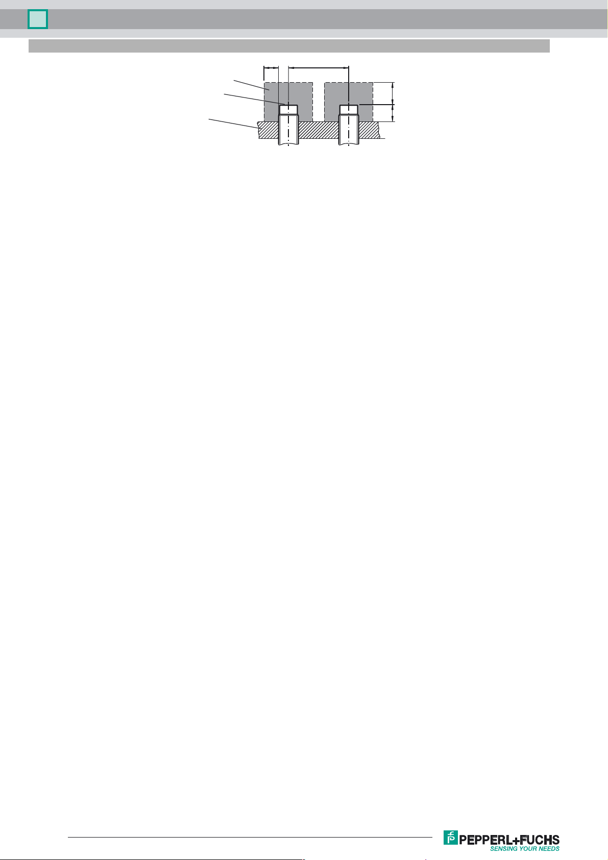
0 mm
0 mm
20 mm
60 mm
5 ... 15 V
B
≤ 1.5 mA
≥ 2.5 mA
1G; 1D
EN 60947-5-6:2000
IEC 60947-5-6:1999
EN 60947-5-2:2007
IEC 60947-5-2:2007
2
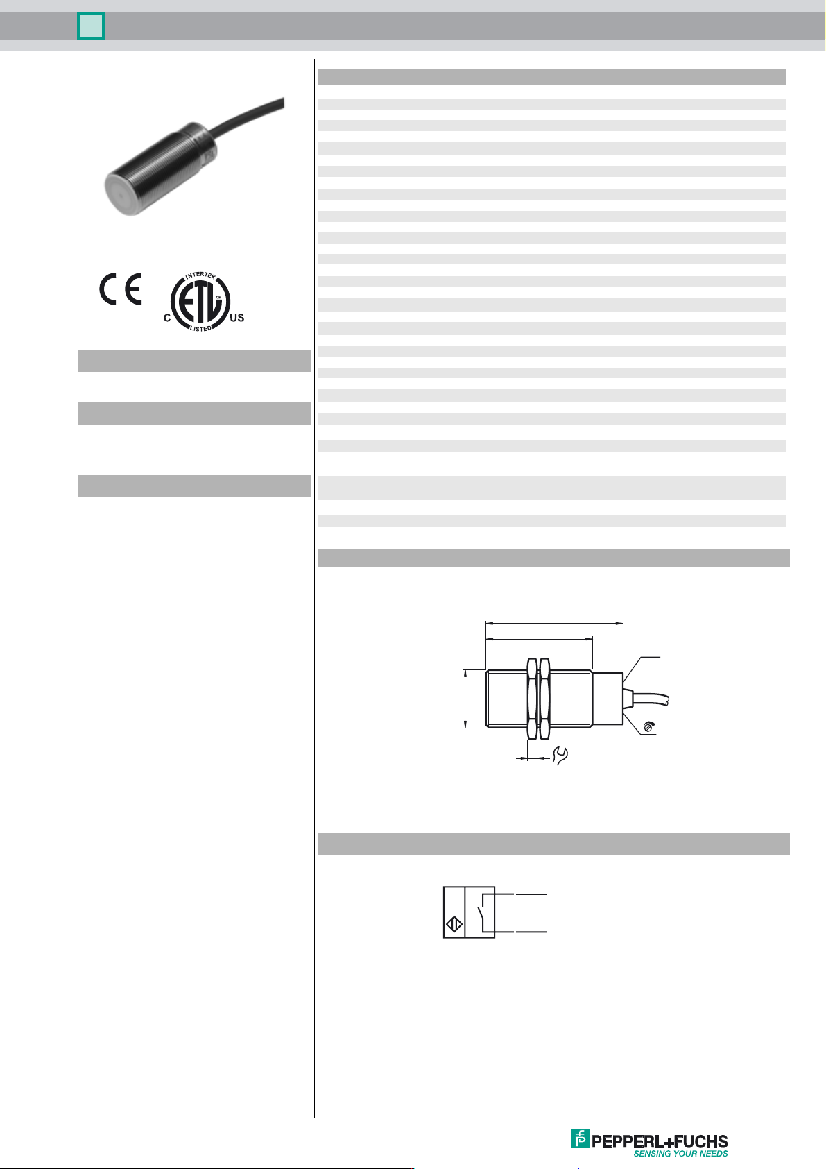
Dimensions
Electrical Connection
M30 x 1.5
BN
BU
70
55
LED
5
36
L+
L-
Release date: 2016-11-09 09:18 Date of issue: 2016-11-09 245596_eng.xml
Refer to “General Notes Relating to Pepperl+Fuchs Product Information”.
1
Capacitive sensor CCB10-30GS55-N1
Installation Conditions
B F
metal-free zone
sensing face
support
CA
Release date: 2016-11-09 09:18 Date of issue: 2016-11-09 245596_eng.xml
Refer to “General Notes Relating to Pepperl+Fuchs Product Information”.
2

Capacitive sensor CCB10-30GS55-N1
Equipment protection level Ga
Instruction Manual electrical apparatus for hazardous areas
Device category 1G
EC-Type Examination Certificate BVS 13 ATEX E 074 X
CE marking 0102
ATEX marking ¬ II 1G Ex ia IIC T1-T6 Ga
Standards EN 60079-0:2012, EN 60079-11:2012, EN 60079-26:2007
Appropriate type CCB10-30GS55-N1...
Effective internal inductivity C
Effective internal inductance L
Ge n e r a l The apparatus has to be operated according to the appropriate data in the data sheet
Highest permissible ambient temperature
T6 when Pi = 100 mW, Ui = 15 V, Ii =30 mA
T5 when Pi = 100 mW, Ui = 15 V, li = 30 mA
T4 when Pi = 100 mW, Ui = 15 V, Ii = 30 mA
T3, T2, T1 when Pi = 100 mW, Ui = 15 V, Ii = 30 mA
Installation, commissioning Laws and/or regulations and standards governing the use or intended usage goal
Maintenance No changes can be made to apparatus, which are operated in hazardous areas.
Special conditions
Electrostatic charge
i
i
for use in hazardous areas with gas, vapour and mist
Ignition protection "Intrinsic safety"
≤ 250 nF
≤ 200 µH
and in this instruction manual.
The EU-type examination certificate has to be observed. The special conditions
must be adhered to!
The ATEX directive generally applies only to the use of electrical apparatus under
atmospheric conditions. When using the apparatus outside atmospheric conditions,
a reduction in the permissible ignition energy must be taken into account where
appropriate.
40 °C (104 °F)
40 °C (104 °F)
80 °C (176 °F)
100 °C (212 °F)
must be observed.
The intrinsic safety is only assured in connection with an appropriate related apparatus and according to the proof of intrinsic safety.
The associated apparatus must satisfy the requirements of category ia.
Due to the possible danger of ignition, which can arise due to faults and/or transient
currents in the equipotential bonding system, galvanic isolation of the power supply
and signal circuit is preferable. Associated apparatus without electrical isolation must
only be used if the appropriate requirements of IEC 60079-14 are met.
Repairs to these apparatus are not possible.
Electrostatic charges must be avoided on the mechanical housing components.
Dangerous electrostatic charges on the mechanical housing components can be
avoided by incorporating these in the equipotential bonding.
Alternatively, for devices with cable connections, connect the ground wire (yellow/
green) that is connected galvanically to the metal bushing.
Release date: 2016-11-09 09:18 Date of issue: 2016-11-09 245596_eng.xml
Refer to “General Notes Relating to Pepperl+Fuchs Product Information”.
3

Capacitive sensor CCB10-30GS55-N1
Equipment protection level Da
Instruction Manual electrical apparatus for hazardous areas
Device category 1D for use in hazardous areas with combustible dust
EC-Type Examination Certificate BVS 13 ATEX E 074 X
CE marking 0102
ATE X m ar king ¬ II 1D Ex ia IIIC T101°C Da
Standards EN 60079-0:2012; EN 60079-11:2012
Appropriate type CCB10-30GS55-N1...
Effective internal inductivity C
Effective internal inductance L
Ge n e r a l The apparatus has to be operated according to the appropriate data in the data sheet
Permissible ambient temperature range -20 ... 90 °C (-4 ... 194 °F)
Installation, commissioning Laws and/or regulations and standards governing the use or intended usage goal
Maintenance No changes can be made to apparatus, which are operated in hazardous areas.
Special conditions
Electrostatic charge
i
i
type of protection intrinsic safety "ia"
≤ 250 nF
≤ 200 µH
and in this instruction manual.
The EU-type examination certificate has to be observed.
The special conditions must be adhered to!
must be observed.
The intrinsic safety is only assured in connection with an appropriate related apparatus and according to the proof of intrinsic safety.
If the apparatus is placed entirely in Zone 20, the supply cable is introduced via a
cable duct positioned close by in Zone 20 or 21.
Repairs to these apparatus are not possible.
EN 50281-1-2 requirements, including those relating to dust deposits and temperatures, must be met.
Electrostatic charges must be avoided on the mechanical housing components.
Dangerous electrostatic charges on the mechanical housing components can be
avoided by incorporating these in the equipotential bonding.
Alternatively, for devices with cable connections, connect the ground wire (yellow/
green) that is connected galvanically to the metal bushing.
If the apparatus is placed entirely in Zone 20, the supply cable must be protected
against electrostatic charge using a metal braid or pipe woven into the equipotential
bonding.
Release date: 2016-11-09 09:18 Date of issue: 2016-11-09 245596_eng.xml
Refer to “General Notes Relating to Pepperl+Fuchs Product Information”.
4
 Loading...