


Singleturn absolute encoder BVS58
Technical data
General specifications
Detection type photoelectric sampling
Device type Singleturn absolute encoder
Electrical specifications
Model Number
BVS58
Features
• Industrial standard
housing Ø58 mm
• 13 Bit singleturn
• Output code: gray and binary
• Transfer of position data with 4 ASInterface slaves
• Parameterization and addressing
via AS-Interface
• Servo or clamping flange
Description
In modern machines and systems, binary sensors
and actuators are connected together via AS-Interface.
Until now it was necessary to go back to the use of
costly conventional wiring when wanting to use absolute encoders. The reason for this was that the
handshake mode with the control module of the
analogue profile proved to be too slow for positioning tasks.
In order to meet the real-time demands of many applications, a multi-slave solution using the BVS58
AS-Interface rotary encoders was created. The position value of 13 Bits in length is transferred within
a single cycle via the 4 integrated AS-Interface
chips to the master and made available to the PLC.
This singleturn absolute encoder is available either
in clamping flange design with a shaft 10 mm in diameter x 20 mm or in servo flange design with a
shaft 6 mm in diameter x 10 mm.
Operating voltage U
No-load supply current I
Linearity ± 1 LSB
Output code programmable, Gray code, binary code
Code course (counting direction) programmable,
Interface
Interface type AS-Interface
Resolution
Single turn 13 Bit
Overall resolution 13 Bit
Transfer rate max. 0.167 MBit/s
Standard conformity AS-Interface
Connection
Connector type V1, M12, 4-pin
Standard conformity
Degree of protection DIN EN 60529, IP65
Climatic testing DIN EN 60068-2-3, no moisture condensation
Emitted interference EN 61000-6-4:2007
Noise immunity EN 61000-6-2:2005
Shock resistance DIN EN 60068-2-27, 100 g, 11 ms
Vibration resistance DIN EN 60068-2-6, 10 g, 10 ... 2000 Hz
Ambient conditions
Operating temperature -20 ... 70 °C (-4 ... 158 °F)
Storage temperature -25 ... 85 °C (-13 ... 185 °F)
Mechanical specifications
Material housing: powder coated aluminum
Mass approx. 330 g
Rotational speed max. 10000 min
Moment of inertia 30 gcm
Starting torque ≤ 2 Ncm
Shaft load
Axial 40 N at max. 6000 min
Radial 60 N at max. 6000 min
B
0
29.5 ... 31.6 V DC
max. starting current 155 mA , operating current max. 85 mA
cw ascending (clockwise rotation, code course ascending)
cw descending (clockwise rotation, code course
descending)
flange: aluminum
shaft: stainless steel
-1
2
-1
10 N at max. 12000 min
20 N at max. 12000 min
-1
-1
-1
Release date: 2014-04-14 15:31 Date of issue: 2016-01-26 t37283_eng.xml
Refer to “General Notes Relating to Pepperl+Fuchs Product Information”.
1
Singleturn absolute encoder BVS58
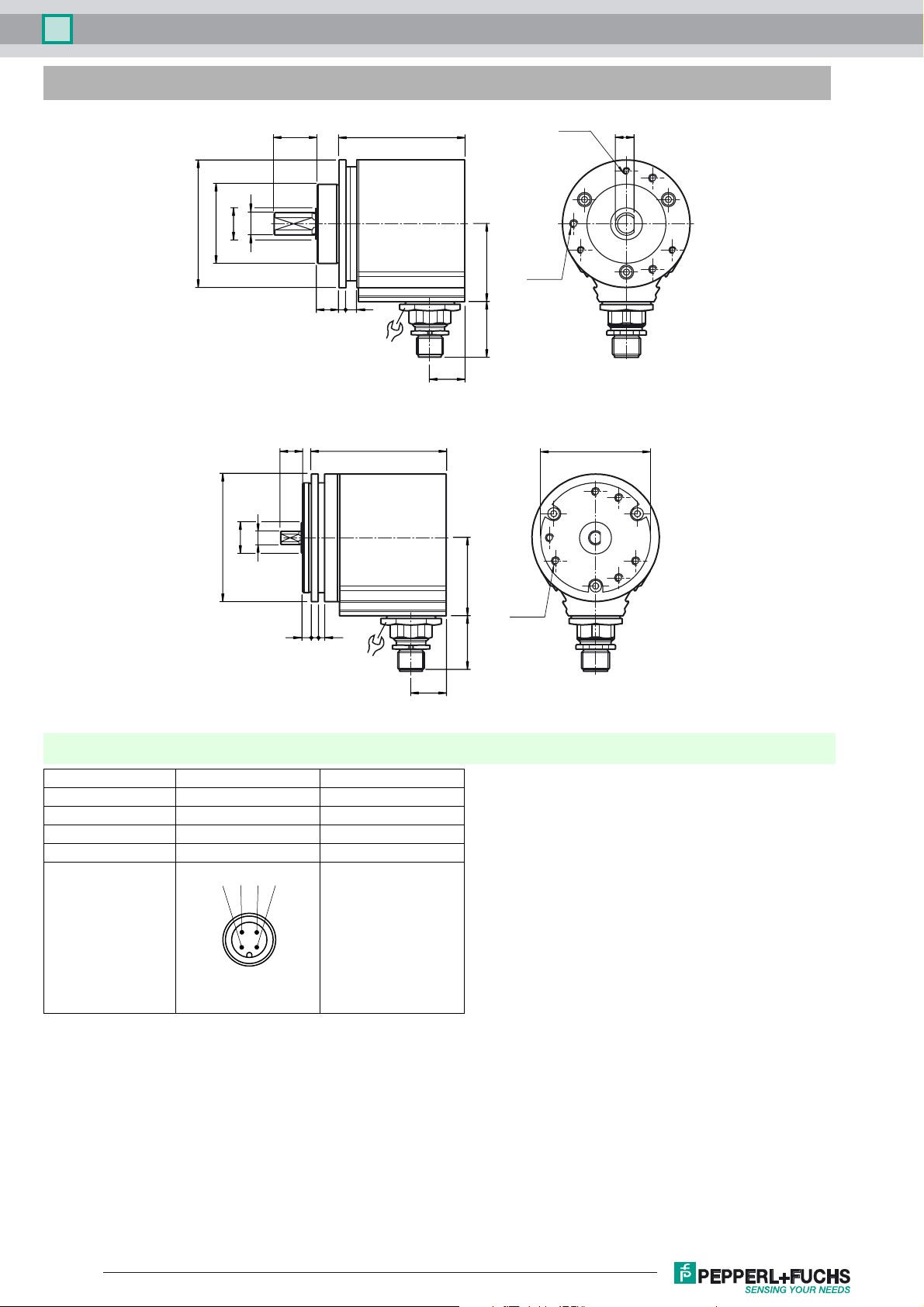
Dimensions
ø 58
ø 14
ø 36f8
Camping flange
ø 58
ø 10h7
ø 14
6h7
19.5+1
10+1
10 3 5
24
61.3
57,3
3 x M3
5 deep
35,5
3 x M4
5 deep
25.2
16
9
50h7
433
24
Servo flange
Electrical connection
Signal V1 connector, 4-pin Explanation
AS-Interface + 1
Reserved 2 Not wired
AS-Interface - 3
Reserved 4 Not wired
143
2
35.525.2
6 x M4
6 deep
16
Release date: 2014-04-14 15:31 Date of issue: 2016-01-26 t37283_eng.xml
Refer to “General Notes Relating to Pepperl+Fuchs Product Information”.
2

Singleturn absolute encoder BVS58
Addresses
Slave A Slave B Slave C Slave D
Preset address 1 2 3 4
IO code 7000
ID code FFFF
When readdressing by means of a bus master or a programming device, it is absolutely essential to assign different addresses to the four integrated AS-Interface chips.
Parameter bits
The four parameter bits of slave A are used to set the parameters of the rotary encoder.
The parameter bits of slave B, C and D are not used.
Status of
parameter bit
0 Gray code Transfer with flag bits Descending counting direction for clockwise rotation Not used
1 Binary code Transfer without flag bits Ascending counting direction for clockwise rotation Not used
P0 P1 P2 P3
Data bits
From the AS-Interface master to the rotary encoder
Data from the AS-Interface master are transferred to the rotary encoder via slave A, which works bidirectionally. Slaves B, C and D work unidirectionally,
i.e. they are incapable of receiving data.
Status of
D0/D1 or D2/D3
00 Normal mode Position data are not saved!
01 Rotary encoder is set to ¼ of the singleturn resolution. Position data are saved!
10 Rotary encoder is set to 0. Position data are saved!
11 Normal mode Position data are not saved!
When a change is made in data bits D2 and D3 from 01 to 10 or vice-versa, position data are resaved in the rotary encoder.
D0/D1 D2/D3
From the rotary encoder to the AS-Interface master
Depending on the value of parameter bit P1 of slave A, data transfer to the AS-Interface master takes place with or without flag bits.
P1 = 1: Transfer without flag bits
Slave A Slave B Slave C Slave D
D0 D1 D2 D3 D0 D1 D2 D3 D0 D1 D2 D3 D0 D1 D2 D3
Bit 0 Bit 1 Bit 2 Bit 3 Bit 4 Bit 5 Bit 6 Bit 7 Bit 8 Bit 9 Bit 10 Bit 11 Bit 12 Not used!
P1 = 0: Transfer with flag bits MA, MB, MC, MD
Slave A Slave B Slave C Slave D
D0 D1 D2 D3 D0 D1 D2 D3 D0 D1 D2 D3 D0 D1 D2 D3
Bit 0 Bit 1 Bit 2 MA Bit 3 Bit 4 Bit 5 MB Bit 6 Bit 7 Bit 8 MC Bit 9 Bit 10 Bit 11 MD
Slave A
Slave A
Operating modes
Address assignments for the four slaves
The AS-Interface master accesses all slaves one after the other within an AS-Interface cycle in order to transfer output data to slave A or to read in input
data from the slaves. The singleturn absolute encoder uses only four AS-Interface chips to transfer the position data that are 13 bits wide, i. e. four slave
addresses are assigned.
Since these four slaves are queried one after the other, the data may originate from any one of four different sampling times. To minimise the influence of
this effect, sequential addresses (n, n+1, n+2 and n+3) should be assigned to slaves A, B, C and D.
Furthermore, it should be noted that slave A is responsible for controlling the functions of the absolute encoder. If the order of the slaves is changed (D = n,
C = n+1, B = n+2, A = n+3), the output word, which is supposed to be transmitted by the function control module of the absolute encoder, will not be transmitted until slaves D, C and B have been read in.
Release date: 2014-04-14 15:31 Date of issue: 2016-01-26 t37283_eng.xml
Refer to “General Notes Relating to Pepperl+Fuchs Product Information”.
3

Singleturn absolute encoder BVS58
A memory command would thus only take effect for slave A. The command would not take effect for slaves that were already read until the next read cycle.
Data consistency would be lost because of the change of order.
Temporary storage and transfer with flag bits
If individual telegrams of the four slaves to the AS-Interface master suffer interference, it may happen in spite of temporary storage in the rotary encoder that
the data that are transferred to the control module do not all originate from the same position data set.
Transferring one flag bit for each slave makes it possible for the control module to check which position data set an individual data set belongs to by comparing the four flag bits. Data bit D2 is used for this purpose.
Example:
Slave A
Cycle Slave A Slave B Slave C Slave D
1 0 XXX0 XXX0 XXX0 XXX0
2 1 XXX1 XXX1 XXX1 XXX1
3 0 XXX0 XXX0 XXX0 XXX0
4 1 XXX1 XXX1 XXX1 XXX1
etc.
Bit D2 is influenced by the control module. Bit 4 of the input data corresponds to the value of this bit for each slave.
D2 is set to 0 in cycle 1. If the value of bit 4 of a slave were "1", that value would be derived from another cycle. This is a simple way to recognise data
consistency.
Transferring the flag bits, however, reduces the usable position data from 13 bits to 12. Masking out the fourth bit of each slave increases slightly the effort
of putting together the position data set in the control module.
Data bit D2
Order code
Position data
BV 5 8N– AVR0NN–
Option 2
N Not expanded
Output code
N Selectable, binary/Gray
Option 1
0 No option
Exit position
R Radial
Connection type
AV Plug connector M12 x 1, 4-pin
Shaft dimension/flange version
011 Shaft Ø10 mm x 20 mm with clamping flange
032 Shaft Ø6 mm x 10 mm with servo flange
Housing material
N Aluminium, powder coated
Principle of operation
M Multiturn
S Singleturn
Shaft version
V Solid shaft
Data format
B AS-Interface
Bit combinations (resolution)
Multiturn encoder (see table)
Singleturn encoder
0016
(16 bit = 65536)
Release date: 2014-04-14 15:31 Date of issue: 2016-01-26 t37283_eng.xml
Refer to “General Notes Relating to Pepperl+Fuchs Product Information”.
4
 Loading...