

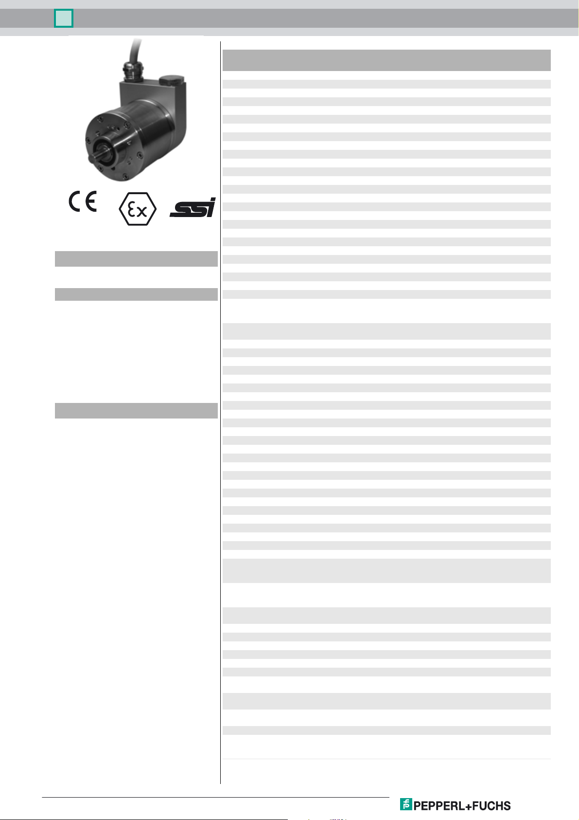
Multiturn absolute encoder AVM78E
Technical Data
General specifications
Detection type photoelectric sampling
Device type Multiturn absolute encoder
Functional safety related parameters
MTTFd 30 a
Mission Time (TM) 20 a
L
7.7 E+9 at 3000 rpm
10
Diagnostic Coverage (DC) 0 %
Electrical specifications
0102
SYNCHRON SERIELLES INTERFACE
Model Number
AVM78E
Features
•Up to 30 Bit multiturn
• ATEX approval
• IECEx approval
• Flameproof enclosure
• Removable connection cap
• Galvanically isolated RS 422
interface
Description
This absolute rotary encoder returns a position
value corresponding to the shaft position via the SSI
interface.
In order to obtain the position data, the controller
sends a start sequence to the absolute rotary
encoder. The encoder then responds
synchronously to the pulses from the controller with
the position data.
The modular design enables you to order the
absolute rotary encoder so that it fulfills your
requirements. A listing of the part options can be
found in the ordering information.
You can select the counting direction via 2
functional inputs and set the zero position.
Operating voltage U
No-load supply current I
Linearity ± 2 LSB at 16 Bit, ± 1 LSB at 13 Bit, ± 0,5 LSB at 12 Bit
Output code Gray code, binary code
Code course (counting direction) see input 1
Interface
Interface type SSI
Monoflop time 20 ± 10 µs
Resolution
Single turn up to 16 Bit
Multiturn up to 14 Bit
Overall resolution up to 30 Bit
Transfer rate 0.1 ... 2 MBit/s
Standard conformity RS 422
Input 1
Input type Selection of counting direction (cw/ccw)
Signal voltage
High 10 ... 30 V or open input
Low 0 ... 2 V
Input current < 6 mA
Switch-on delay < 10 ms
Input 2
Input type zero-set (PRESET)
Signal voltage
High 10 ... 30 V
Low 0 ... 2 V
Input current < 6 mA
Signal duration ≥ 100 ms
Switch-on delay < 10 ms
Connection
Cable Ø 10.2 mm, Radox 9 x 0.5 mm
Terminal compartment see ordering information
Standard conformity
Degree of protection DIN EN 60529, IP66
Climatic testing DIN EN 60068-2-3, no moisture condensation
Emitted interference EN 61000-6-4:2007
Noise immunity EN 61000-6-2:2005
Shock resistance DIN EN 60068-2-27, 100 g, 3 ms
Vibration resistance DIN EN 60068-2-6, 10 g, 10 ... 2000 Hz
Ambient conditions
Operating temperature -40 ... 70 °C (-40 ... 158 °F)
Storage temperature -40 ... 85 °C (-40 ... 185 °F)
Mechanical specifications
Material
Combination 1 housing: anodized aluminum
Combination 2 (Inox) housing: stainless steel 1.4404 / AISI 316L
Mass approx. 2600 g (combination 1)
Rotational speed max. 3000 min
Moment of inertia 180 gcm
Starting torque ≤ 4 Ncm
Shaft load
Axial 60 N
Radial 80 N
Data for application in connection with
hazardous areas
EU-type examination certificate ITS 15 ATEX 18372X
Marking ¬ II 2G Ex d IIC T5 Gb
Directive conformity
Directive 2014/34/EU IEC 60079-0:2011 , EN 60079-0:2012+A11:2013 , IEC
B
0
10 ... 30 V DC
max. 90 mA
cw descending (clockwise rotation, code course
descending)
cw ascending (clockwise rotation, code course ascending)
2
flange: anodized aluminum
shaft: Stainless steel 1.4401 / AISI 316
flange: stainless steel 1.4404 / AISI 316L
shaft: Stainless steel 1.4401 / AISI 316
approx. 3900 g (combination 2)
IECEx ITS 15.0061X
¬ II 2D Ex tb IIIC T100°C Db
60079-1:2014 , EN 60079-1:2014 , IEC 60079-31:2013 , EN
60079-31:2014
-1
2
Release date: 2019-08-23 11:32 Date of issue: 2019-08-23 t157829_eng.xml
Refer to "General Notes Relating to Pepperl+Fuchs Product Information".
1
Multiturn absolute encoder AVM78E
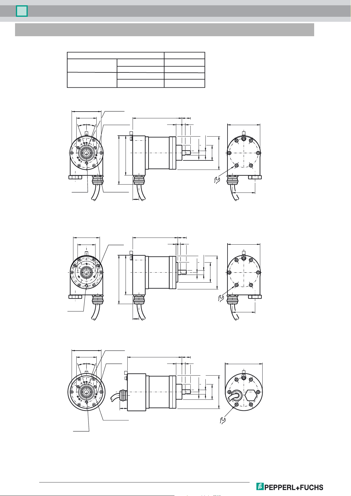
Dimensions
Encoder length L
Ver si on
Radial cable exit
Axial cable exit
ø69 ±0.1
ø48 ±0.1
15°
15°
3 x M6,
6 deep
3 x 120°
Clamping flange
Servo flange
Clamping flange
Servo flange
ø 3, 8 deep
3 x M3, 6 deep
3 x 120°
95
117
3 x M4, 6 deep
3 x 120°
Length L
118 mm
118 mm
134 mm
134 mm
L 20
16 5
-0.05
-0.10
4
ø10 g7
ø36 f7
ø78
78
3.5 Nm
±0.5 Nm
15
54
Clamping flange, cable exit radial
3 x M6,
10 deep
3 x 120°
ø60 ±0.1
ø42 ±0.1
ø69 ±0.1
ø48 ±0.1
15°
15°
3 x M4,
9 deep
3 x 120°
117
ø 3, 8 deep
3 x M3,
6 deep
3 x 120°
L
95
20
45
-0.05
-0.10
4
ø10 g7
ø50h7
78
ø78
3.5 Nm
±0.5 Nm
54
15
Servo flange, radial cable exit
L 20
16 5
-0.05
-0.10
ø10 g7
4
ø78
ø36 f7
22
92
3 x M4, 6 deep
3 x M6,
6 deep
3 x 120°
Refer to "General Notes Relating to Pepperl+Fuchs Product Information".
3 x 120°
3.5 Nm ±0.5 Nm
Clamping flange, axial cable exit
Release date: 2019-08-23 11:32 Date of issue: 2019-08-23 t157829_eng.xml
2

Multiturn absolute encoder AVM78E
ø60 ±0.1
ø42 ±0.1
22
3 x M6, 10 deep
3 x 120°
3 x M4, 9 deep
3 x 120°
Servo flange, axial cable exit
Shaft 12 mm
425 425
8
4
M17 x 0.75
L 20
2 flats
at 120°
45
-0.05
-0.10
4
ø12h7
ø10 g7
ø50h7
ø78
3.5 Nm ±0.5 Nm
2 flats
at 120°
8
4
M17 x 0.75
92
ø12h7
Electrical connection
Signal Cable Terminal compartment
Ground wire green-yellow Grounding terminal
GND (rotary encoder) 1 1
(rotary encoder) 2 2
+U
b
Pulse (+) 3 5
Pulse (-) 4 6
Data (+) 5 8
Data (-) 6 7
Preset 7 4
Counting direction 8 3
12345678
Release date: 2019-08-23 11:32 Date of issue: 2019-08-23 t157829_eng.xml
Refer to "General Notes Relating to Pepperl+Fuchs Product Information".
3
Multiturn absolute encoder AVM78E
Description
The Synchronous Serial Interface was specially developed for transferring the output data of an absolute encoder to a control device. The control module
sends a clock bundle and the absolute encoder responds with the position value.
Thus only 4 lines are required for the clock and data, no matter what the resolution of the rotary encoder is. The RS 422 interface is optically isolated from the
power supply.
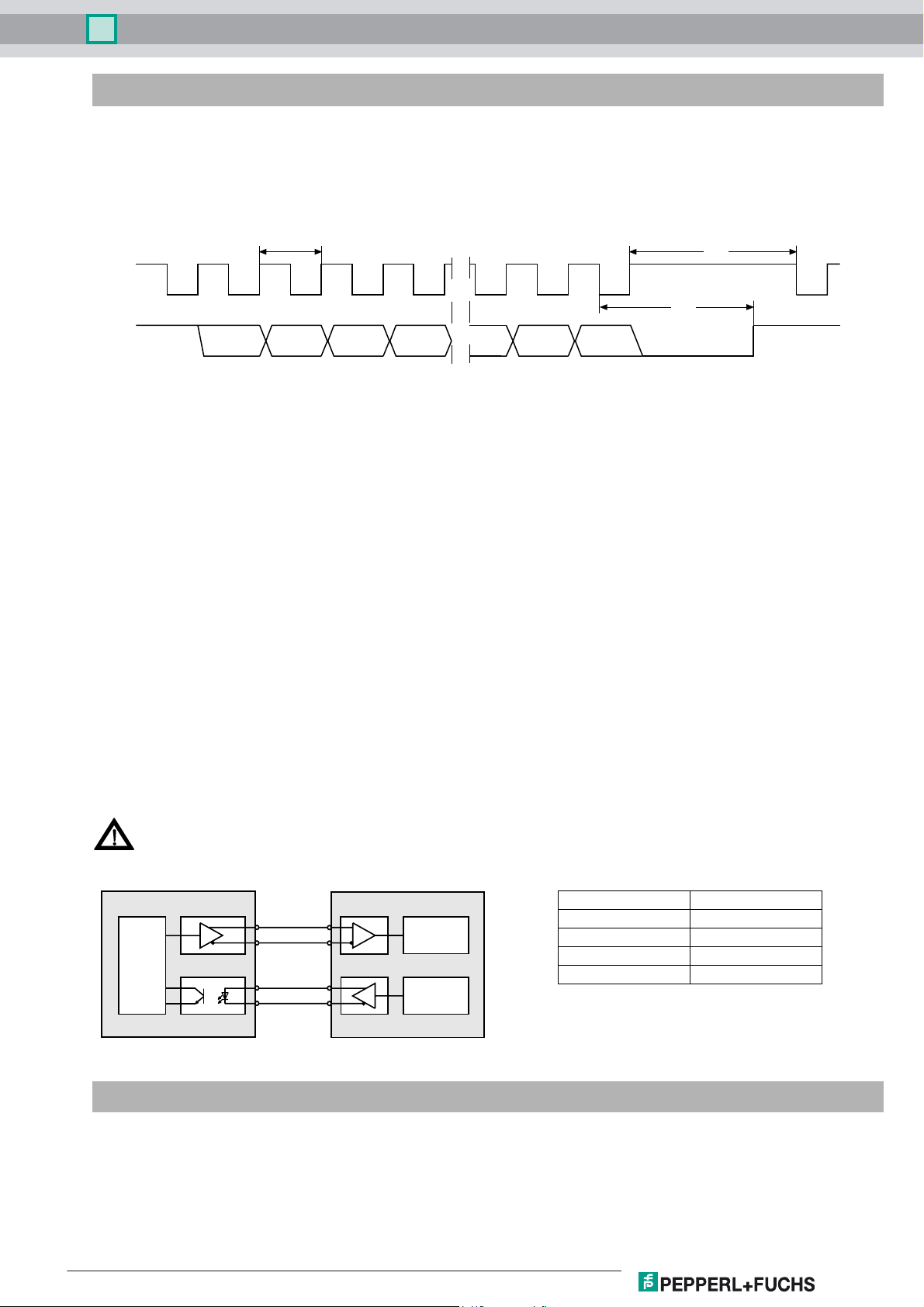
SSI signal course Standard
Clock +
Data +
T
D
n
MSB
D1, ..., Dn: T = 1/f:
S:
MSB:
LSB:
D
n-1
Position data
Special bit
Most significant bit
Least significant bit
D
n-2
D
n-3
D
2
D
1
T
m
T
:
p
:
S
LSB
Duration of period of clock signal
Monoflop time 10 µs ... 30 µs
Clock pause
T
p
T
m
≥ monoflop time (Tp ≥ T
≤ 1 MHz
)
m
SSI output format Standard
• At idle status signal lines "Data +" and "Clock +" are at high level (5 V).
• The first time the clock signal switches from high to low, the data transfer in which the current information (position data (Dn) and special bit (S)) is
stored in the encoder is introduced.
• The highest order bit (MSB) is applied to the serial data output of the encoder with the first rising pulse edge.
• The next successive lower order bit is transferred with each following rising pulse edge.
• After the lowest order bit (LSB) has been transferred the data line switches to low until the monoflop time Tm has expired.
• No subsequent data transfer can be started until the data line switches to high again or the time for the clock pause Tp has expired.
• After the clock sequence is complete, the monoflop time Tm is triggered with the last falling pulse edge.
• The monoflop time Tm determines the lowest transmission frequency.
SSI output format ring slide operation (multiple transmission)
• In ring slide operation, multiple transmission of the same data word over the SSI interface makes it possible to offer the possibility of detecting
transmission errors.
• In multiple transmission, 25 bits are transferred per data word in standard format.
• If the clock change is not interrupted after the last falling pulse edge, ring slide operation automatically becomes active. This means that the information
that was stored at the time of the first clock change is generated again.
• After the first transmission, the 26
a new current data word will be transmitted with the following pulses.
th
pulse controls data repetition. If the 26th pulse follows after an amount of time greater than the monoflop time Tm,
If the pulse line is exchanged, the data word is generated offset.
Ring slide operation is possible up to max. 13 bits.
Block diagram Line length
Line length in m Baudrate in kHz
Data +
Data -
Logic
Clock +
Clock -
Rotary encoder Interface electronics
Receiver
Clock
generator
< 50 < 400
< 100 < 300
< 200 < 200
< 400 < 100
Inputs
The selection of the counting direction input (cw/ccw) is activated with 0-level. The zero-set input (PRESET 1) is activated with 1-level.
Release date: 2019-08-23 11:32 Date of issue: 2019-08-23 t157829_eng.xml
Refer to "General Notes Relating to Pepperl+Fuchs Product Information".
4

Multiturn absolute encoder AVM78E
zero-set input (PRESET 1)
IN
Filter
U
e
⊥
Pull down
Logic
Input for selection of counting direction (cw/ccw)
IN
U
Pull up
Filter
e
⊥
Ordering information
AVM78E – 0 0 –
Housing material
N Aluminum
I Stainless steel 1.4404 (AISI 316L)
Output code
B Binary
G Gray
Option 2
0 Zeroing (preset) and counting direction (F/R)
Exit position
A axial
R radial
Connection type
K2 Cable, 9 strands, 2 m
K5 Cable, 9 strands, 5 m
KR Terminal compartment, 1 cable gland, 1 stopping plug
Flange version
1 Clamping flange
2 Servo flange
Shaft dimension
01 Shaft Ø10 mm x 20 mm
02 Shaft Ø12 mm x 25 mm
Option 1
E Explosion-proof, standard IP66
Functional principle
M Multiturn
Typ e of s ha f t
V Solid shaft
Data format
A SSI interface
Logic
Number of singleturn bits
12 4096
16 65536
Number of multiturn bits
12 4096
14 16384
Release date: 2019-08-23 11:32 Date of issue: 2019-08-23 t157829_eng.xml
Refer to "General Notes Relating to Pepperl+Fuchs Product Information".
5
 Loading...