

Multiturn absolute encoder AVM58-0
Technical data
General specifications
Detection type photoelectric sampling
Device type Multiturn absolute encoder
Functional safety related parameters
MTTFd 150 a
Mission Time (TM) 20 a
L
1.9 E+11 at 6000 rpm and 20/40 N axial/radial shaft load
10
Diagnostic Coverage (DC) 0 %
Electrical specifications
SYNCHRON SERIELLES INTERFACE
Model Number
AVM58-0
Features
• Industrial standard
housing Ø58 mm
•30 Bit multiturn
• Data transfer up to 2 MBaud
• Optically isolated RS 422 interface
•Servo or clamping flange
• Zero-set function
• Up to 4096 pulses on incremental
track
Description
This multiturn absolute encoder with modern fast
technology transmits a position value
corresponding to the shaft setting via the SSI
interface (Synchronous Serial Interface). The
maximum resolution of the AVM58 is maximum
65536 steps per revolution at 16384 revolutions.
The devices of the AVM58 series are equipped with
a microcontroller.
The control module sends a clock bundle to the
absolute encoder to obtain the position data. The
rotary encoder then sends the position data
synchronous to the cycles of the control module.
It is possible to select the following items with
function inputs
• the counting direction and
• the zero-set function (preset value)
This multiturn absolute encoder is available in a
clamping flange design with a shaft diameter of
10 mm x 20 mm, or in a servo flange design with a
shaft diameter of 6 mm x 10 mm. The electrical
connection is made by a 12-pin round plug
connector. It is also possible to obtain a version with
a 1 m cable connector.
Operating voltage U
No-load supply current I
Time delay before availability t
Linearity ± 2 LSB at 16 Bit, ± 1 LSB at 13 Bit, ± 0,5 LSB at 12 Bit
Output code Gray code, binary code
Code course (counting direction) cw descending (clockwise rotation, code course
Interface
Interface type SSI ; SSI + incremental track
Monoflop time 20 ± 10 µs
Resolution
Single turn up to 16 Bit
Multiturn 14 Bit
Overall resolution up to 30 Bit
Transfer rate 0.1 ... 2 MBit/s
Voltage drop UB - 2.5 V
Standard conformity RS 422
Input 1
Input type Selection of counting direction (cw/ccw)
Signal voltage
High 4.5 ... 30 V
Low 0 ... 2 V
Input current < 6 mA
Switch-on delay < 10 ms
Input 2
Input type zero-set (PRESET 1)
Signal voltage
High 4.5 ... 30 V
Low 0 ... 2 V
Input current < 6 mA
Signal duration ≥ 100 ms
Switch-on delay < 10 ms
Output
Output type RS422, Push/Pull
Signal output A+B+/A+/B
Pulses 1024, 2048, 4096
Connection
Connector type 9416 (M23), 12-pin, type 9416L (M23), 12-pin
Cable Ø7 mm, 6 x 2 x 0.14 mm
Standard conformity
Degree of protection DIN EN 60529, IP65 (without shaft seal) ; DIN EN 60529,
Climatic testing DIN EN 60068-2-3, no moisture condensation
Emitted interference DIN EN 61000-6-4
Noise immunity DIN EN 61000-6-2
Shock resistance DIN EN 60068-2-27, 100 g, 6 ms
Vibration resistance DIN EN 60068-2-6, 20 g, 10 ... 2000 Hz
Ambient conditions
Operating temperature -40 ... 85 °C (-40 ... 185 °F)
Storage temperature -40 ... 85 °C (-40 ... 185 °F)
Mechanical specifications
Material
Combination 1 housing: powder coated aluminum
Combination 2 (Inox) housing: stainless steel
Mass approx. 460 g (combination 1)
Rotational speed max. 12000 min
Moment of inertia 50 gcm
Starting torque < 5 Ncm
Shaft load
Axial 40 N
Radial 110 N
B
0
v
4.5 ... 30 V DC (SSI, SSI + RS422) ; 10 ... 30 V DC (SSI +
Push/Pull)
max. 180 mA
< 250 ms
descending)
2
, 1 m
IP66/IP67 (with shaft seal)
flange: aluminum
shaft: stainless steel
flange: stainless steel
shaft: stainless steel
approx. 800 g (combination 2)
-1
2
Release date: 2017-09-28 14:44 Date of issue: 2017-09-28 t49169_eng.xml
Refer to “General Notes Relating to Pepperl+Fuchs Product Information”.
Approvals and certificates
UL approval cULus Listed, General Purpose, Class 2 Power Source
1
Multiturn absolute encoder AVM58-0
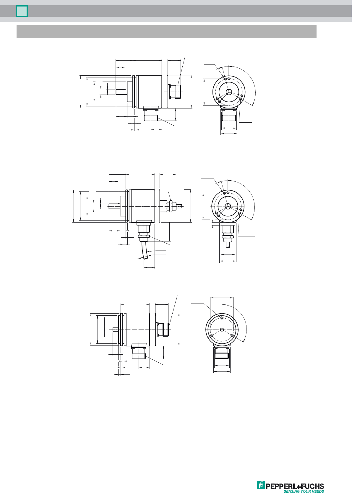
Dimensions
Connector 9416*, axial
ø58
ø53
ø36f7
ø10h8
~2830 53
18
1
d**
3 x M3
6 deep
ø48
15˚
3 x 120˚
Clamping flange
1
ø10h8
ø53
ø58
ø36f7
Clamping flange
30
18
20 10
20 10
24
3
20
3
53
3
3
R100
~18
Connector 9416*, radial
** Aluminium: d = 59, stainless steel: d = 61
~28
Cable gland
PG9, axial
~33
Cable gland
radial
PG9,
ø7
** Aluminium: d = 59, stainless steel: d = 61
d**
3 x M3
6 deep
ø48
15˚
5
3 x M4
6 deep
25
30
3 x 120˚
3 x M4
6 deep
25
30
ø6h7
ø58
ø50f7
Servo flange
Connector 9416*, axial
53
10
3
3
4
~28
24
20
Connector 9416*, radial
** Aluminium: d = 59, stainless steel: d = 61
3 x M4
6 deep
d**
ø42
3 x 120˚
25
30
Release date: 2017-09-28 14:44 Date of issue: 2017-09-28 t49169_eng.xml
Refer to “General Notes Relating to Pepperl+Fuchs Product Information”.
2
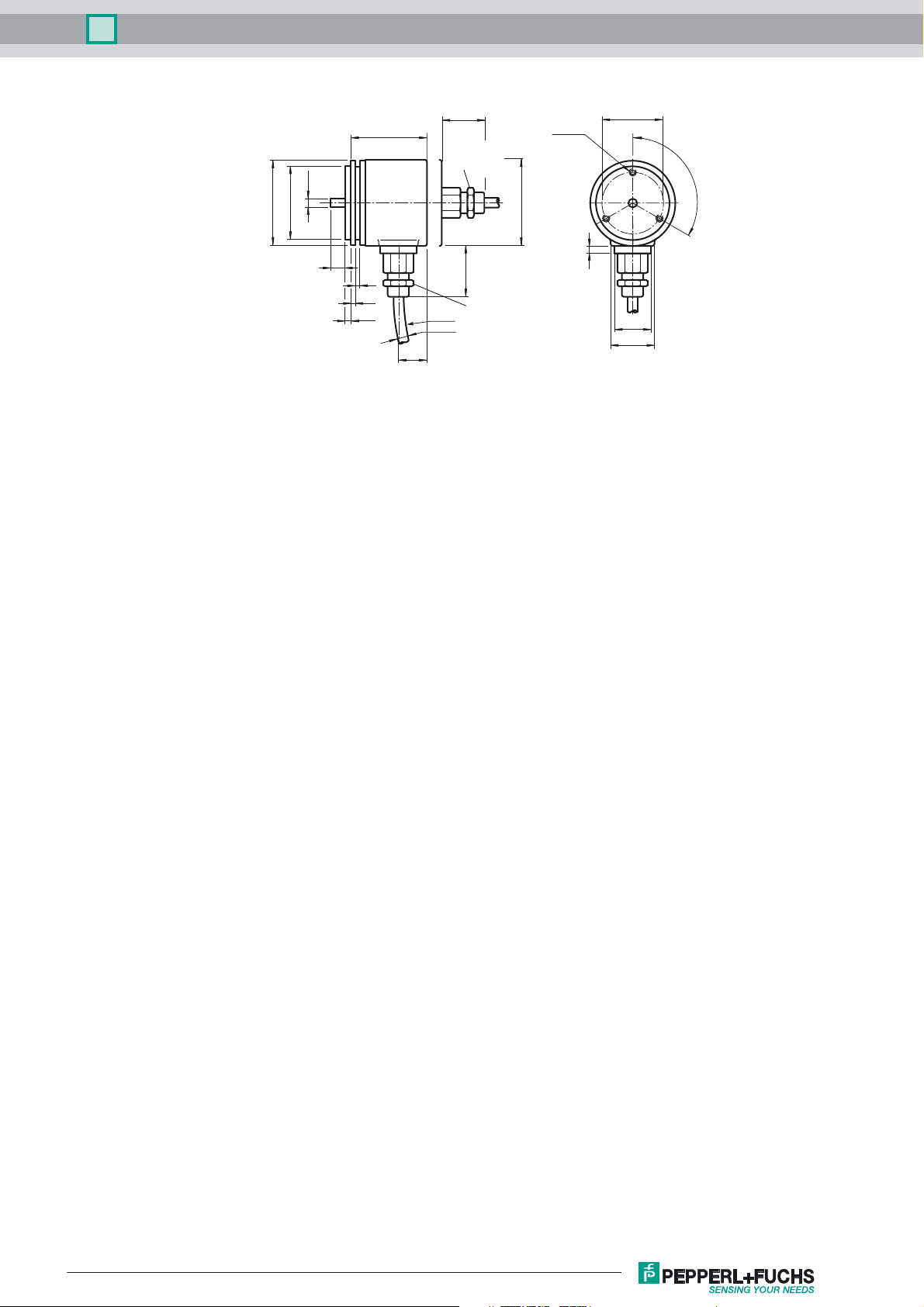
Multiturn absolute encoder AVM58-0
ø6h7
ø58
ø50f7
Servo flange
~28
53
Cable gland
PG9, axial
10
3
3
4
~18
~33
Cable gland
R100
ø7
** Aluminium: d = 59, stainless steel: d = 61
PG9,
radial
3 x M4
6 deep
d**
ø42
3 x 120˚
5
25
30
Release date: 2017-09-28 14:44 Date of issue: 2017-09-28 t49169_eng.xml
Refer to “General Notes Relating to Pepperl+Fuchs Product Information”.
3

Multiturn absolute encoder AVM58-0
Electrical connection
Signal Cable Ø7 mm, 12-core Connector 9416, 12-pin
Connector 9416L, 12-
pin
Explanation
GND (encoder) White 1 1 Power supply
(encoder) Brown 2 8 Power supply
U
b
Clock (+) Green 3 3 Positive cycle line
Clock (-) Yellow 4 11 Negative cycle line
Data (+) Grey 5 2 Positive transmission data
Data (-) Pink 6 10 Negative transmission data
A Black 7 12 Incremental track A
V/R Red 8 5 Input for selection of counting direction
PRESET 1 Blue 9 9 zero-setting input
B Grey/Pink 10 4 Incremental track B
Violet 11 6 Incremental track A
A
B Red/Blue 12 7 Incremental track B
1211
9810
4
3
5
12
6
7
8711
9112
5
6
4
10
3
2
Release date: 2017-09-28 14:44 Date of issue: 2017-09-28 t49169_eng.xml
Refer to “General Notes Relating to Pepperl+Fuchs Product Information”.
4

Multiturn absolute encoder AVM58-0
Description
The Synchronous Serial Interface was specially developed for transferring the output data of an absolute encoder to a control device. The control module
sends a clock bundle and the absolute encoder responds with the position value.
Thus only 4 lines are required for the clock and data, no matter what the resolution of the rotary encoder is. The RS 422 interface is optically isolated from the
power supply.
SSI signal course Standard
Clock +
Data +
T
D
n
MSB
D1, ..., Dn: T = 1/f:
S:
MSB:
LSB:
D
n-1
Position data
Special bit
Most significant bit
Least significant bit
D
n-2
D
n-3
D
2
D
1
T
m
T
p
:
:
S
LSB
Duration of period of clock signal
Monoflop time 10 µs ... 30 µs
Clock pause
T
p
T
m
≥ monoflop time (Tp ≥ T
≤ 1 MHz
)
m
SSI output format Standard
• At idle status signal lines "Data +" and "Clock +" are at high level (5 V).
• The first time the clock signal switches from high to low, the data transfer in which the current information (position data (Dn) and special bit (S)) is
stored in the encoder is introduced.
• The highest order bit (MSB) is applied to the serial data output of the encoder with the first rising pulse edge.
• The next successive lower order bit is transferred with each following rising pulse edge.
• After the lowest order bit (LSB) has been transferred the data line switches to low until the monoflop time Tm has expired.
• No subsequent data transfer can be started until the data line switches to high again or the time for the clock pause Tp has expired.
• After the clock sequence is complete, the monoflop time Tm is triggered with the last falling pulse edge.
• The monoflop time Tm determines the lowest transmission frequency.
SSI output format ring slide operation (multiple transmission)
• In ring slide operation, multiple transmission of the same data word over the SSI interface makes it possible to offer the possibility of detecting
transmission errors.
• In multiple transmission, 25 bits are transferred per data word in standard format.
• If the clock change is not interrupted after the last falling pulse edge, ring slide operation automatically becomes active. This means that the information
that was stored at the time of the first clock change is generated again.
• After the first transmission, the 26th pulse controls data repetition. If the 26th pulse follows after an amount of time greater than the monoflop time Tm,
a new current data word will be transmitted with the following pulses.
If the pulse line is exchanged, the data word is generated offset.
Ring slide operation is possible up to max. 13 bits.
Block diagram Line length
Data +
Data -
Logic
Clock +
Clock -
Rotary encoder Interface electronics
Release date: 2017-09-28 14:44 Date of issue: 2017-09-28 t49169_eng.xml
Refer to “General Notes Relating to Pepperl+Fuchs Product Information”.
Receiver
Clock
generator
Line length in m Baudrate in kHz
< 50 < 400
< 100 < 300
< 200 < 200
< 400 < 100
5

Multiturn absolute encoder AVM58-0
Signal outputs
! cw - with view onto the shaft
A
A
B
B
Inputs
The selection of the counting direction input (V/R) is activated with 0-level. The zero-set input (PRESET 1) is activated with 1-level.
zero-set input (PRESET 1)
IN
Filter
U
e
⊥
Pull down
Logic
Input for selection of counting direction (V/R)
IN
U
Pull up
Filter
e
Logic
⊥
Release date: 2017-09-28 14:44 Date of issue: 2017-09-28 t49169_eng.xml
Refer to “General Notes Relating to Pepperl+Fuchs Product Information”.
6

Multiturn absolute encoder AVM58-0
Accessories
For type Accessories Name/defining feature Order code
D1: Ø10 mm, D2: Ø10 mm 9401
Couplings
Measurement wheels with
circumference of 500 mm
AVM58*-011
Measurement wheels with
circumference of 200 mm
Mounting aids
Couplings
AVM58*-032
Mounting aids
All Connectors
For additional information on the accessories, please see the "Accessories" section.
D1: Ø10 mm, D2: Ø10 mm 9404
D1: Ø10 mm, D2: Ø10 mm 9409
D1: Ø10 mm, D2: Ø10 mm KW
Plastic 9101, 10
Pimpled rubber 9102, 10
Knurled aluminium 9103, 10
Knurled plastic 9112, 10
Plastic 9108, 10
Pimpled rubber 9109, 10
Knurled aluminium 9110, 10
Knurled plastic 9113, 10
Mounting bracket 9203
Mounting bracket 9213
D1: Ø6 mm, D2: Ø6 mm 9401
D1: Ø6 mm, D2: Ø6 mm 9402
D1: Ø6 mm, D2: Ø6 mm 9404
D1: Ø6 mm, D2: Ø6 mm 9409
D1: Ø6 mm, D2: Ø6 mm KW
Mounting bracket and set 9300 and 9311-3
Eccentric clamping elements 9310-3
Cable socket 9416
Cable socket 9416L
Release date: 2017-09-28 14:44 Date of issue: 2017-09-28 t49169_eng.xml
Refer to “General Notes Relating to Pepperl+Fuchs Product Information”.
7

Multiturn absolute encoder AVM58-0
Order code
AVM58 – 0 –
Number of bits singleturn
12 4096 (standard)
13 8192
16 65536
Number of bits multiturn
12 4096 (standard)
14 16384
Options
N Stand ard
1 Incremental track 1024 pulses, Push/Pull
2 Incremental track 2048 pulses, Push/Pull
3 Incremental track 4096 pulses, Push/Pull
4 Incremental track 1024 pulses, RS422
5 Incremental track 2048 pulses, RS422
6 Incremental track 4096 pulses, RS422
Output code
B Binary
G Gray
Exit position
A Axial
R Radial
Connection type
K1 Cable Ø7 mm, 6 x 2 x 0.14 mm², 1 m
AA Plug connector type 9416, 12-pin
AB Plug connector type 9416L, 12-pin
Shaft dimension/flange version
011 Shaft Ø10 mm x 20 mm with clamping flange
032 Shaft Ø6 mm x 10 mm with servo flange
Housing material
N Aluminium, powder coated
I Inox*
Principle of operation
M Multiturn
Shaft version
V Solid shaft
Data format
A SSI (Synchronous Serial Interface) *Housing material I only available with axial exit position.
Release date: 2017-09-28 14:44 Date of issue: 2017-09-28 t49169_eng.xml
Refer to “General Notes Relating to Pepperl+Fuchs Product Information”.
8
 Loading...