

Page 1

MANUAL
AS-I CC-LINK GATEWAY
FACTORY AUTOMATION
Page 2

AS-i CC-Link Gateway
With regard to the supply of products, the current issue of the following document is applicable: The
General Terms of Delivery for Products and Services of the Electrical Industry, published by the
Central Association of the Electrical Industry (Zentralverband Elektrotechnik und Elektroindustrie
(ZVEI) e.V.) in its most recent version as well as the supplementary clause: "Expanded reservation
of proprietorship"
Page 3

AS-i CC-Link Gateway
Table of contents
Table of contents
AS-i CC-Link Gateway
1 Introduction...........................................................................................6
2 Declaration of conformity ....................................................................7
2.1 Declaration of conformity................................................................................ 7
3 Safety.....................................................................................................8
3.1 Symbols relevant to safety.............................................................................. 8
3.2 General notes on safety ..................................................................................8
3.3 Disposal ............................................................................................................ 8
4 General ..................................................................................................9
4.1 Product information......................................................................................... 9
4.1.1 AS-i CC-Link Gateway ..................................................................................................... 9
4.2 AS-i 3.0 specification....................................................................................... 9
5 Specifications .....................................................................................10
5.1 Technical data ................................................................................................ 10
5.1.1 Data sheet....................................................................................................................... 10
6 Installation...........................................................................................11
6.1 Safety notes.................................................................................................... 11
6.2 Installing in the control cabinet .................................................................... 12
6.3 Removing........................................................................................................ 12
6.4 Dimensions [mm]........................................................................................... 13
7 Electrical connection..........................................................................14
7.1 AS-i bus connection ......................................................................................14
7.2 Connections ................................................................................................... 14
7.2.1 AS-i and power supply terminal assignments ............................................................15
7.3 Front view and connections.......................................................................... 16
7.3.1 Electrical connection: VBG-CCL-K20-D-BV ................................................................16
7.4 CC-Link interface .......................................................................................... 17
7.5 Chip card......................................................................................................... 17
14.4.2015
3
Page 4

AS-i CC-Link Gateway
Table of contents
7.6 Indicators and operating elements .............................................................. 18
7.6.1 LED indicators – master................................................................................................ 18
7.6.1.1 CC-Link status LED (green/red) flashing sample ......................................................... 19
7.6.2 Buttons ........................................................................................................................... 19
8 Commissioning...................................................................................20
8.1 Commissioning via the device ..................................................................... 20
8.1.1 Switching to advanced display mode .......................................................................... 20
8.1.2 Setting the CC-Link address 14................................................................................... 20
8.1.3 Connecting AS-i Slaves ................................................................................................21
8.1.4 Quick setup .................................................................................................................... 22
8.2 Error tracing................................................................................................... 23
8.2.1 Faulty slaves ..................................................................................................................23
8.2.2 Error display (last error)................................................................................................ 23
8.2.3 Addressing ..................................................................................................................... 24
8.2.3.1 Assigning address 6 to slave currently at address 2 .................................................... 24
8.2.4 Local parameter setting of Gateways .......................................................................... 25
8.2.5 Replacing the chip card ................................................................................................26
8.2.6 Using the chip card ....................................................................................................... 26
8.2.6.1 Card unformatted .......................................................................................................... 27
8.2.6.2 Data not compatible ......................................................................................................27
8.2.6.3 Card empty ...................................................................................................................27
8.2.6.4 Data compatible ............................................................................................................ 28
8.2.6.5 Data in the device and on the chip card identical .........................................................28
8.2.6.6 Data in the device and on the chip card not identical ...................................................28
9 Operation in display mode.................................................................29
10 Data transmission modes ..................................................................30
10.1 Selecting the data transmission mode ........................................................ 30
10.2 Summary of modes ....................................................................................... 31
10.3 Standard mode............................................................................................... 32
10.3.1 Remote IO Points........................................................................................................... 32
10.3.2 Buffer Memory Area ...................................................................................................... 33
10.3.3 Message Transmission ................................................................................................. 36
10.4 Compatibility mode for VBG-CCL-G4F ........................................................ 37
10.4.1 Remote IO Points........................................................................................................... 37
10.4.2 Buffer Memory Area ...................................................................................................... 38
10.5 CC-Link V1 Mode ........................................................................................... 41
10.5.1 Remote IO Points........................................................................................................... 41
10.5.2 Buffer Memory Area ...................................................................................................... 42
10.6 Compatibility Mode for FX2N-32ASI-M ........................................................ 46
10.6.1 Remote IO Points........................................................................................................... 46
10.6.2 Buffer Memory Area ...................................................................................................... 47
10.7 Compatibility Mode for HK-ASICC ............................................................... 49
10.7.1 Remote IO Points........................................................................................................... 49
10.7.2 Buffer Memory Area ...................................................................................................... 50
11 Advanced Diagnostics for AS-i Masters...........................................51
11.1 List of corrupted AS-i Slaves (LCS)51
4
14.4.2015
Page 5

AS-i CC-Link Gateway
Table of contents
11.2 Protocol analysis: Counters for corrupted data telegrams ....................... 51
11.3 Clear the diagnostic buffer............................................................................ 52
11.4 Offline Phase for Configuration Errors ........................................................52
11.5 Functions of the AS-i Fault Detector ............................................................ 52
11.5.1 Earth/Ground Fault Detector ........................................................................................52
11.5.2 Noise Detector ...............................................................................................................53
11.5.3 Over-voltage Detector ...................................................................................................53
11.6 Substitute values ........................................................................................... 54
12 Accessing command interface..........................................................55
12.1 Using BFM ...................................................................................................... 55
12.2 Using message transmission ....................................................................... 57
13 Codes indicated by the display.........................................................59
14 Glossary ..............................................................................................61
15 Reference List.....................................................................................66
15.1 Manual: “AS-i 3.0 Command Interface“ ....................................................... 66
14.4.2015
5
Page 6
AS-i CC-Link Gateway
Introduction
1. Introduction
Congratulations
You have chosen a device manufactured by Pepperl+Fuchs. Pepperl+Fuchs develops, produces and distributes electronic sensors and interface modules for the
market of automation technology on a worldwide scale.
Before installing this equipment and put into operation, read this manual carefully.
This manual containes instructions and notes to help you through the installation
and commissioning step by step. This makes sure bring such a trouble-free use of
this product. This is for your benefit, since this:
• ensures the safe operation of the device
• helps you to exploit the full functionality of the device
• avoids errors and related malfunctions
• avoids costs by disruptions and any repairs
• increases the effectiveness and efficiency of your plant
Keep this manual at hand for subsequent operations on the device.
After opening the packaging please check the integrity of the device and the number of pieces of supplied.
Symbols used
The following symbols are used in this manual:
Information!
This symbol indicates important information.
Attention!
This symbol warns of a potential failure. Non-compliance may lead to interruptions of
the device, the connected peripheral systems, or plant, potentially leading to total malfunctioning.
Warning!
This symbol warns of an imminent danger. Non-compliance may lead to personal injuries that could be fatal or result in material damages and destruction.
Contact
If you have any questions about the device, its functions, or accessories, please
contact us at:
Pepperl+Fuchs GmbH
Lilienthalstraße 200
68307 Mannheim
Telephone: +49 621 776-4411
Fax: +49 621 776-274411
E-Mail: fa-info@pepperl-fuchs.com
14.4.2015
6
Page 7

AS-i CC-Link Gateway
Declaration of conformity
2. Declaration of conformity
2.1 Declaration of conformity
This product was developed and manufactured under observance of the applicable European standards and guidelines.
Information!
A Declaration of Conformity can be requested from the manufacturer.
The product manufacturer, Pepperl+Fuchs GmbH, D-68307 Mannheim, has a
certified quality assurance system that conforms to ISO 9001.
14.4.2015
7
Page 8
AS-i CC-Link Gateway
Safety
3. Safety
3.1 Symbols relevant to safety
Information!
This symbol indicates important information.
Attention!
This symbol warns of a potential failure. Non-compliance may lead to interruptions of
the device, the connected peripheral systems, or plant, potentially leading to total malfunctioning.
Warning!
This symbol warns of an imminent danger. Non-compliance may lead to personal injuries that could be fatal or result in material damages and destruction.
3.2 General notes on safety
Only instructed specialist staff may operate the device in accordance with the operating manual.
User modification and or repair are dangerous and will void the warranty and exclude the manufacturer from any liability. If serious faults occur, stop using the device. Secure the device against inadvertent operation. In the event of repairs, return the device to your local Pepperl+Fuchs representative or sales office.
The connection of the device and maintenance work when live may only be carried out by a qualified electrical specialist.
The operating company bears responsibility for observing locally applicable safety regulations.
Store the not used device in the original packaging. This offers the device optimal
protection against impact and moisture.
Ensure that the ambient conditions comply with regulations.
3.3 Disposal
Information!
Electronic waste is hazardous waste. Please comply with all local ordinances when
disposing this product!
The device does not contain batteries that need to be removed before disposing it.
8
14.4.2015
Page 9
AS-i CC-Link Gateway
General
4. General
4.1 Product information
This system manual applies to the following Pepperl+Fuchs equipment:
4.1.1 AS-i CC-Link Gateway
Article no.
VBG-CCL-K20-D-BV
The AS-i CC-Link Gateways serve to connect AS-i systems to the superordinate
CC-Link. The gateways act as a master for AS-i and as a slave on CC-Link.
4.2 AS-i 3.0 specification
The AS-i CC-Link Gateway is designed according to the AS-i 3.0 specification.
field bus interface
number of AS-i Masters
RS 232 diagnostic interface
Recognition of duplicate addresses
CC-Link
Tab. 4-1. Function range of "AS-i CC-Link Gateway"
14.4.2015
9
Page 10
AS-i CC-Link Gateway
Connection
Connections AS-i: COMBICON
CC-Link: screw terminal blocks
Interface
CC-Link interface according to CC-Link specification
Baud rates 156 KBps up to 10 MBps
Type remote device
Occupied stations 2-4 (depending on operating mode)
CC-Link functions imaging of the AS-i slaves as RW data on CC-Link.
complete diagnosis and configuration via CC-Link
AS-i
Cycle time 150ȝs * (number of slaves + 2)
Operating current power supply A, approx. 200 mA out of AS-i
Operating voltage AS-i voltage 30V DC
Display
LCD menu, displaying AS-i slave addresses and error messages
LED power voltage ON
LED cc-link state of CC-Link
LED config error configuration error
LED U AS-i AS-i voltage o.k.
LED AS-i active AS-i in normal operation
LED prg enable automatic address programming enabled
LED prj mode configuration mode active
Environment
Applied standards EN 61 000-6-2
EN 61 000-6-4
Housing Stainless Steel
Operating temperature 0°C … +55°C
Storage temperature -25°C … +85°C
Protection category (EN 60 529) IP20
Allowable shock -and vibration stress according to EN 61 131-2
Voltage of insulation ≥ 500V
Dimensions (L / W / H in mm) 85 / 120 / 83
Weight 520 g
Pin assignment:
DA blue
DG yellow
SLD n/a
DB white
F G n/a
Signal Color
1
2
3
4
5
Specifications
5. Specifications
5.1 Technical data
The technical data are placed in the data sheet. Please view the current version
on the web page: http://www.pepperl-fuchs.com.
5.1.1 Data sheet
10
14.4.2015
Page 11
AS-i CC-Link Gateway
Installation
6. Installation
Read instruction:
Before working with this unit: read these instructions carefully and completely. All notes on safety and
specifications of the device manual and the manual for the configuration software are to be considered!
6.1 Safety notes
Ensure appropiate installation:
Electrical installation is to be performed by trained expert personnel. During installation care must be
taken that supply and signal leads and also the AS-i bus cable are laid separately from power cables. In
the switchgear cabinet it must be ensured that appropriate spark-quenching equipment is used with contactors. Where drive motors and brakes are used, attention must be paid to the installation instructions in
the corresponding operating instructions. Please note that the maximum line length of the AS-i bus cable
is 100 m. Cables above that length require the use of a suitable circuit extension.
HAZARDOUS VOLTAGE:
Before any installation, maintenance or modification work: Disconnect your system from the supply network. Ensure that it cannot be reconnected inadvertently!
You are requested to make sure that the unit will be recycled by the end of its service life.
14.4.2015
11
Page 12
AS-i CC-Link Gateway
+-+
-
+
-
[1]
[2]
+-+
-
+
-
Installation
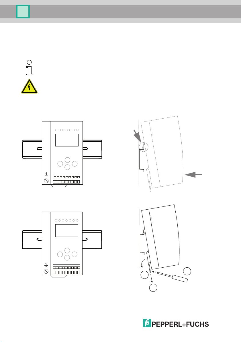
6.2 Installing in the control cabinet
The AS-i CC-Link Gateway is installed in the control cabinet on 35mm DIN rails
per DIN EN 50 022.
Information!
The enclosure of the AS-i/Gateway is made of stainless steel. The unit is also suitable
for exposed wall mounting.
Warning!
Cover the top of the gateway when doing any drilling work above the unit. No particles,
especially metal chips, should be allowed to enter the housing, since this could cause a
short circuit.
To install, place the unit on the upper edge of the DIN rail and then snap in the
lower edge.
6.3 Removing
To remove, press the holding clamps [2] down using a screwdriver [1], press the
unit firmly against the upper rail guide and lift out.
12
3
1
2
14.4.2015
Page 13
AS-i CC-Link Gateway
55
85
120
7
76
Installation
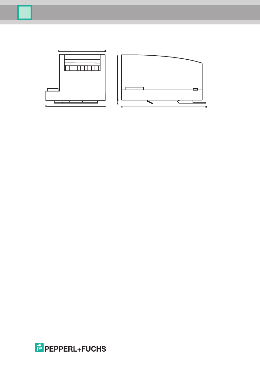
6.4 Dimensions [mm]
14.4.2015
13
Page 14
AS-i CC-Link Gateway
Yellow ASi ribbon cable
Blue
AS-i-
Brown
AS-i+
2-conductor AS-i round cable
(Recommended: flexible power cable
H05VV-F2x1,5 per DIN VDE 0281)
Blue
AS-i-
Brown
AS-i+
10
10
AWG 24 ... 12
0,2 ... 2,5 mm
2
0,2 ... 2,5 mm
2
Electrical connection
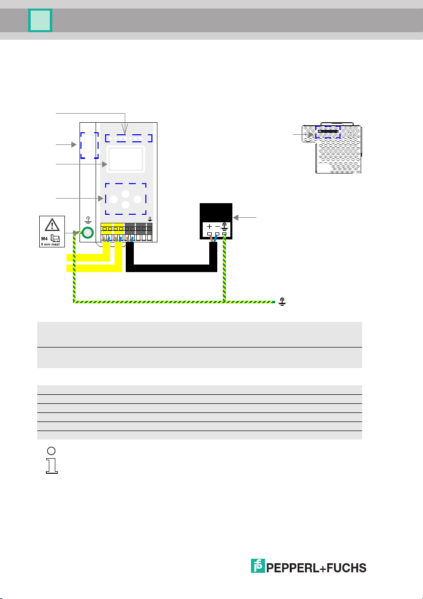
7. Electrical connection
7.1 AS-i bus connection
Information!
Electrical work is to be performed only by electrical technicians.
7.2 Connections
14
Ambient air temperature
Temperature rating for cable
Use copper conductors only
0°C +55 °C
60/75oC
14.4.2015
Page 15

AS-i CC-Link Gateway
Electrical connection
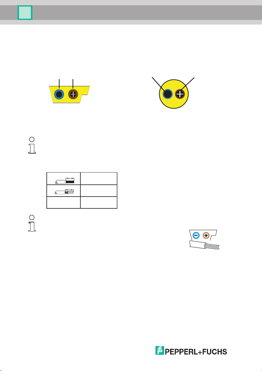
7.2.1 AS-i and power supply terminal assignments
Caution!
At the black cable for power supply no slaves or repeaters may be attached. At the
yellow cable for AS-i circuit no power supplies or further masters may be attached.
Even in case of a fault, the output voltage of the power supply shall be 42 V or less.
Information!
The function ground can be connected either to the grounding screw or to the terminal.
The function ground should be made with as short a cable as possible to ensure good
EMC characteristics.
Therefore function grounding using the grounding screw is preferred.
14.4.2015
15
Page 16
AS-i CC-Link Gateway
+-+
-
+
-
+ASI- +ASI-
n.c. n.c.
ASI
+PWR
-
ASI
ASI +PWR– (max. 8 A)
+ASI 1–
+ASI 1–
[2]
[3]
[4]
[5]
[1]
[6]
Electrical connection
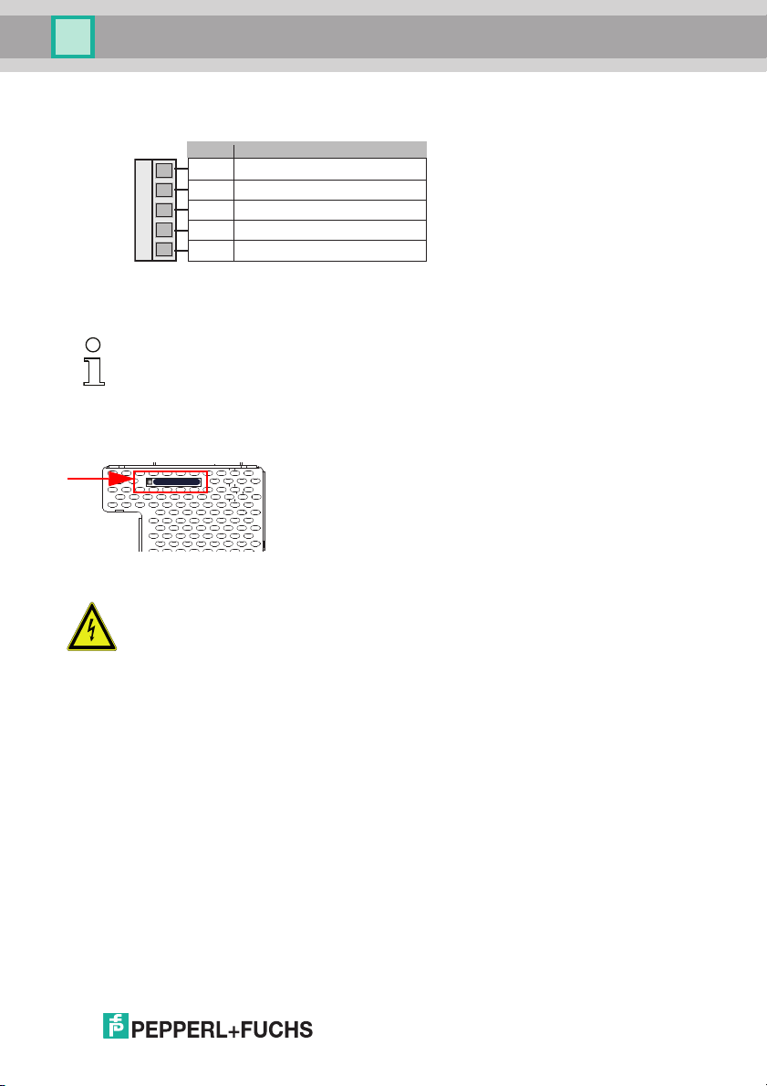
7.3 Front view and connections
7.3.1 Electrical connection: VBG-CCL-K20-D-BV
+ASI–
Connection AS-i circuit
ASI +PWR– (max. 8 A)
Supply voltage AS-i circuit
[1] Chip card
[2] LED status display
[3] Fieldbus interface
[4] LC display
[5] Buttons for hand operation
[6] Power supply
16
Information!
For additional information, please refer to the sections: <AS-i and power supply terminal assignments>.
14.4.2015
Page 17
AS-i CC-Link Gateway
1
2
3
4
5
Signal color
DA blau/ blue/ bleu/ blu/ azul
DB weiss/ white/ blanc/ bianco/ blanco
DG gelb/ yellow/ jaune/ giallo/ amarillo
SLD n/a
FG n/a
Electrical connection
7.4 CC-Link interface
The CC-Link interface connector is designed as a 5-pin COMBICON connector. It
is located on the left hand side of the front panel (see section <Overview of terminals, indicators and operating elements>).
Information!
For better noise performance, SLD (cable shield) should be grounded separately in
10 cm distance to the COMBICON connector.
7.5 Chip card
The configuration is stored in a fixed installed EEPROM and can be overwritten
by the chip card. The chip card does not have to be inserted in operation.
Warning!
Power must always be turned off when removing or inserting the chip card!
14.4.2015
17
Page 18
AS-i CC-Link Gateway
CC-Link
Electrical connection
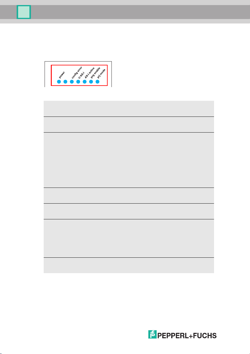
7.6 Indicators and operating elements
7.6.1 LED indicators – master
The LED’s on the front panel of the device indicate:
Power
The AS-i master is receiving sufficient power.
CC-Link (CC-Link status LED)
Flashing sample see chap. <CC-Link status LED (green/red) flashing sample>.
config error
Configuration error.
At least one configured slave is missing, or at least one detected slave is not configured, or for at least one configured and detected slave the actual configuration data
does not match the nominal configuration data, or the master is in the startup process.
This LED flashes if a peripheral fault has been detected for at least one AS-i slave
on the AS-i network. If there are configuration errors as well as periphery faults, only
the configuration error is displayed.
U AS-i
The AS-i network is sufficiently powered.
AS-i active
Normal operation is active
prg enable
Automatic single node replacement is enabled.
Exactly one slave is missing in the protected operating mode. The slave can be
replaced by another slave of the same type with address zero. The master automatically addresses the new slave to the faulty address and thus corrects the configuration error
prj mode
The AS-i master is in configuration mode.
18
14.4.2015
Page 19
AS-i CC-Link Gateway
Electrical connection
7.6.1.1 CC-Link status LED (green/red) flashing sample
C-Control mode (C-Control active)
CC-Link LED CC-Link Error CC-Link Run
flashing green off off
flashing green/red on or flashing off
green off on
flashing green/red on or flashing on
Standard mode (C-Control inactive)
CC-Link LED CC-Link Error CC-Link Run
off off off
red on or flashing off
green off on
red on or flashing on
7.6.2 Buttons
The buttons are used for the following:
Tab. 7-2.
Tab. 7-3.
Mode/
Switching between configuration mode and protected operating mode, and saving
the current AS-i configuration as the nominal configuration.
Set
Selecting the address of and assigning an address to a slave.
OK, ESC
Changing to the advanced display mode.
For additional information see section <Operation in advanced display mode>.
14.4.2015
19
Page 20
AS-i CC-Link Gateway
Menu structure see additional page
Classical display
LCD
.12A
UNKNOWN SLAVE
LCD
CC LINK
QUICK SETUP
SETUP
SLAVE ADR TOOL
Advanced display mode
LCD
CC LINK ADDRESS
CC LINK STATUS
MODE
CC BAUD RATE
INFO
CC LINK ADDRESS
OLD ADDRESS 1
NEW ADDRESS 01
CC LINK ADDRESS
OLD ADDRESS 1
NEW ADDRESS 01
CC LINK
QUICK SETUP
DIAGNOSIS
1x
1x
1x
2x
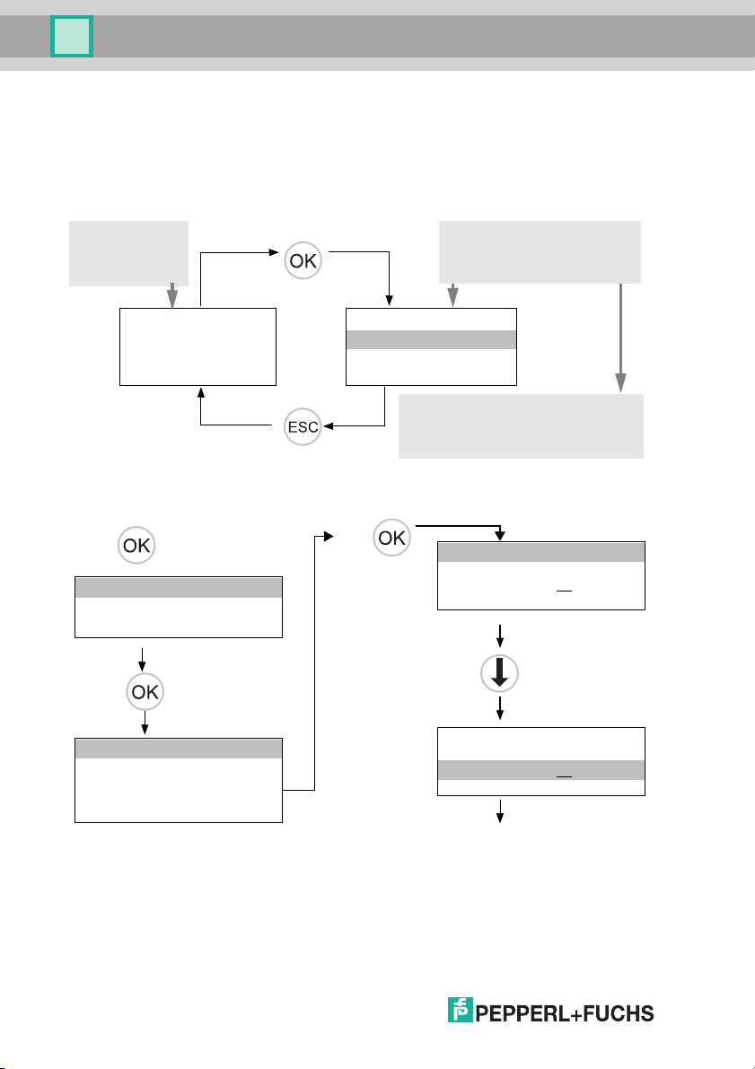
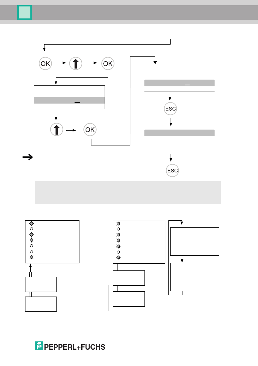
Commissioning
8. Commissioning
8.1 Commissioning via the device
8.1.1 Switching to advanced display mode
8.1.2 Setting the CC-Link address 14
20
14.4.2015
Page 21
AS-i CC-Link Gateway
The device is set to address 1 at the factory.
CC LINK ADDRESS
OLD ADDRESS 1
NEW ADDRESS 10
CC LINK ADDRESS
OLD ADDRESS 1
NEW ADDRESS 14
CC LINK
QUICK SETUP
DIAGNOSIS
New address/baud rate will be used after rebooting the Gateway
2x
1x 1x
4x
1x
2x
2x
Slave 1
AS-i
Slave 5
AS-i
LCD
0.5s
0.5s
Slave 1
AS-i
Slave 5
AS-i
AS-i
prj mode
config error
prg enable
AS-i active
U AS-i
CC-Link
power
AS-i
prj mode
config error
prg enable
AS-i active
U AS-i
CC-Link
power
. 5
. 1
AS-i Master
AS-i Master
LCD
. 41
SEARCHING SLAVES
Commissioning
8.1.3 Connecting AS-i Slaves
14.4.2015
21
Page 22

AS-i CC-Link Gateway
config error
CONFIGURATION OK
...
QUICK SETUP
SETUP
SLAVE ADR TOOL
WARNING:
OUTPUTS MAY BE
RESET
STORE AS-I
CONFIGURATION
STORE + RUN
STORE AS-I
CONFIGURATION
OK
LCD
. 5
STORE + PRJ MODE
STORE +PRJ MODE
config error
Host Error
No connection
10 sec
5sec 5sec
CONFIGURATION OK
config error
Commissioning
8.1.4 Quick setup
The function [QUICK SETUP] enables simple and quick configuration of all
AS-i circuits connected to the AS-i gateway:
[STORE+RUN]
Saves the current configuration of the connected AS-i slaves as a target configuration and moves the gateway to the protected operating mode.
[STORE+PRJ MODE]
Saves the current configuration of the connected AS-i slaves as a target configuration and moves the gateway to the configuration mode.
22
Hotkey
[STORE+RUN]
14.4.2015
Page 23

AS-i CC-Link Gateway
Slave 1
AS-i
Slave 5
AS-i
Slave 24
AS-i
.1
AS-i
prj mode
Config error
prg enable
AS-i active
U AS-i
CC-Link
Power
.24
MISSING SLAVE
MISSING SLAVE
2s
2s
LCD
LCD
AS-i Master
Slave 1
AS-i
Slave 5
AS-i
Slave 24
AS-i
AS-i
24
Slave 1
AS-i
Slave 5
AS-i
Slave 24
AS-i
AS-i
prj mode
Config error
prg enable
AS-i active
U AS-i
CC LINK
Power
prj mode
Config error
prg enable
AS-i active
U AS-i
CC LINK
Power
AS-i Master
AS-i Master
CC LINK error
No connection
LCD
Commissioning
8.2 Error tracing
8.2.1 Faulty slaves
8.2.2 Error display (last error)
14.4.2015
23
Page 24

AS-i CC-Link Gateway
LCD
1. 41
SEARCHING SLAVE
SETUP
SLAVE ADR TOOL
AS-I CIRCUIT 1
AS-I CIRCUIT 2
SLAVE ADR TOOL
OLD ADDRESS 2
NEW ADDRESS 0
PRG
SLAVE ADR TOOL
OLD ADDRESS 2
NEW ADDRESS 6
1. 6
UNKNOWN SLAVE
SLAVE ADR TOOL
OK
PRG
SLAVE ADR TOOL
OLD ADDRESS 2
NEW ADDRESS 6
PRG
Master Slave
Connect module
4x
1x
1x
1x
1x
6x
2x
1x
QUICK SETUP
SLAVE ADR TOOL
CONNECT NEW SLAVE
OLD ADDRESS
NEW ADDRESS
1x
1x
1x
Disconnect field bus!
Commissioning
8.2.3 Addressing
8.2.3.1 Assigning address 6 to slave currently at address 2
24
14.4.2015
Page 25

AS-i CC-Link Gateway
Commissioning
8.2.4 Local parameter setting of Gateways
Konfiguration auf Karte +
Gerät ungleich
(Werkskonfigration
geändert) // Confiugration on
chip card + device not
identical (factory settings
changed) // Configuration sur
carte à puce + dispositif pas
identiques (configuration
d'usine modifié) //
Configurazione sulla scheda
chip + sul dispositivo non
identici (configurazione di
fabbrica modificate) //
Configuración en el tarjeta
chip + dispositivo no idénticos
(configuración de fabrica
modificado)
Konfiguration auf Karte +
Gerät gleich // Configuration
on chip card + device
identical // Configuration sur
carte à puce + dispositif
identiques // Configurazione
sulla scheda chip + sul
dispositivo identici //
Configuración en el tarjeta
Karte leer + formatiert //
Chip card empty + formatted //
Carte à puce vide +
CHIPCARD FOUND
formatée // Scheda chip vuota
+ formattata // Tarjeta chip
vacía + formateada
chip + dispositivo idénticos
Keine Meldung // No
message // Aucun
message // Nessun
DATA WILL
BE SYNCHRONIZED
Keine Aktion erforderlich //
messaggio // Ningún
mensaje
Daten werden vom Gerät auf
Karte übertragen // Data
transferred from device to
chip card // Données
transférées du dispositif à la
CHIPCARD AND DATA
DIFFERENT
CARD->MASTER
MASTER->CARD
Daten kopieren
No action required //
Aucune action requise //
Nessuna azione richiesta //
Ninguna acción requrida
Keine Aktion erforderlich //
carte à puce // Dati trasferiti
dal dispositivo al chip card //
Datos transferidos desde
No action required //
dispositivo de chip card
Karte -> Master oder
Master -> Karte //
Copy data
Card -> Master or
Master -> Card //
Copiez données
Aucune action requise //
Nessuna azione richiesta //
Ninguna acción requrida
Carte -> Maître ou
Maître -> Carte //
Copiare dati
Chipcard -> Master o
Master -> Chipcard //
Copiar datos
TarjetaChip -> Maestro o
Maestro -> TarjetaChip
DATA F ROM
Konfiguration kompatibel
(Werkskonfiguration) //
Configuration compatible
(factory settings) //
Configuration compatible
(configuration d'usine) //
Configurazione compatibile
(configurazione di fabbrica) //
Konfiguration auf Karte nicht
kompatibel mit Gerät //
Configuration on chip card not
compatible with device //
Configuration sur carte à puce
non compatible avec
dispositif // Configurazione
sulla scheda chip non
NEW CHIPCARD
chip non formattata // Tarjeta
chip no formateada
WILL BE FORMATTED
Karte nicht formatiert // Chip
card not formatted // Carte à
puce pas formatée // Scheda
14.4.2015
CHIPCARD TAKEN
Configuración compatible
(configuración de fábrica)
compatibile con il dispositivo //
DATA WILL BE
CHIPCARD NOT
Configuración en la tarjeta
chip no compatible con el
dispositivo
SYNCHRONIZED
Karte wird formatiert // Chip
Daten von Karte auf Gerät
übertragen // Data transferred
from chip card to device //
Données transférées de la
carte à puce au dispositif //
COMPATIBLE
card will be formatted // Carte
à puce sera formatée //
Karte löschen // Clear the
Scheda chip verrà
formattata // Tarjeta chip se
formateará
Keine Aktion erforderlich //
card // Supprimer carte //
Cancellare scheda chip //
No action required //
Dati trasferiti dal chip card al
dispositivo // Datos
transferidos desde chip card
de dispositivo
Keine Aktion erforderlich //
No action required //
Borrar tarjeta chip
Aucune action requise //
Nessuna azione richiesta //
Ninguna acción requrida
Aucune action requise //
Nessuna azione richiesta //
Ninguna acción requrida
25
Page 26

AS-i CC-Link Gateway
[1]
[2]
old
new
[3]
Commissioning
8.2.5 Replacing the chip card
Caution!
Always turn off power before inserting or removing the card!
Power
Supply
8.2.6 Using the chip card
The chip card integrated in the AS-i master is used to read-out and to store configuration data.
26
Power
Supply
14.4.2015
Page 27

AS-i CC-Link Gateway
Commissioning
8.2.6.1 Card unformatted
If an unformatted card is found when the device is started, the following is displayed:
The chip card is formatted and then the data copied to the chip card.
8.2.6.2 Data not compatible
If a card is found whose data are incompatible with the device, the following error
message is displayed:
8.2.6.3 Card empty
The following message is displayed for an empty card:
NEW CHIPCARD
WILL BE FORMATED
AS-I DATA WILL
BE SYNCHRONIZED
CHIPCARD NOT
COMPATIBLE
CHIPCARD FOUND
AS-I DATA WILL
BE SYNCHRONIZED
From this time on all changes are made both in the device and on the chip card.
14.4.2015
27
Page 28

AS-i CC-Link Gateway
Commissioning
8.2.6.4 Data compatible
When starting with an empty device (e.g. after a factory reset) a non-empty card
is found whose data are compatible with the device, the following message is displayed:
AS-I DATA FROM
CHIPCARD TAKEN
The card configuration is written to the device. From this time on all changes are
made both in the device and on the chip card.
8.2.6.5 Data in the device and on the chip card identical
If the card and device are not empty at start and the data are identical, no message is displayed.
8.2.6.6 Data in the device and on the chip card not identical
If the card and device are not empty at start and the data are not identical, an error message is displayed and the card is not synchronized with the device. The
following menu is then automatically opened:
28
CHIPCARD AND
AS-I DATA
DIFFERENT
CARD->MASTER
MASTER->CARD
CONTINUE
Description
CHIP CARD>MASTER: Chip card data are copied to the master
MASTER->CHIPCARD: Master data are copied to the chip card
NEXT: No change to the data
The menu can be exited by pressing the ESC/Service key without changing the
data.
14.4.2015
Page 29

AS-i CC-Link Gateway
Operation in display mode
9. Operation in display mode
Information!
You will find a description of the display menu in the separate document
play_Menue".
"Dis-
14.4.2015
29
Page 30

AS-i CC-Link Gateway
Data transmission modes
10. Data transmission modes
10.1 Selecting the data transmission mode
The selection of the respective data transmission mode takes place in the menu
of the AS-i CC-Link Gateway using the buttons and the display.
Main menu || CC-LINK || MODE ||
CC LINK ADDRESS
CC LINK STATUS
MODE
CC BAUD RATE
INFO
STANDARD
VBG-CCL-G4F COMP
CC-Link V1
FX2N-32ASI-M CP
HK-ASICC COMP
30
Following modes are supported:
• Standard
• Compatibility modes for:
• VBG-CCL-G4F COMP
• CC-Link V1
• FX2N-32ASI-M CP
• HK-ASICC COMP
14.4.2015
Page 31

AS-i CC-Link Gateway
Data transmission modes
10.2 Summary of modes
Standard VBG-
CCL-G4F
Occupied Stations 3 3 4 4 2
Cycle Setting 2 1 1 1 1
Required CC-Link Master V2 V1 V1 V1 V1
Support of 2 AS-i Circuits No No No No No
Support of B-Slaves Yes (Yes) Yes No No
Support of AS-i Safety No No No No No
Support of Analog Slaves Yes Yes Yes No No
Support of AS-i Configuration
via CC-Link
Yes Yes Yes No No
CCLink V1
FX2N32ASI-M
Tab. 10-4. Summary of modes
HKASICC
14.4.2015
31
Page 32

AS-i CC-Link Gateway
Data transmission modes
10.3 Standard mode
• In standard mode, the Gateway occupies 3 stations and has a double cycle
setting.
• The last 2 words are reserved for "Message Transmission".
• The AS-i process data is mapped into the Buffer Memory Area (BFM).
• All acyclic requests are handled by "Message Transmission" using cyclic
data.
10.3.1 Remote IO Points
Address 1514131211109876543210
RXm reserved
RXm+1 AS-i Circuit 1: EC-Flags and Fault Detector
RXm+2 reserved
…
RXm+9
Bit Short Name Name
0 Cfg. OK Configuration OK
1 S0 Slave Address 0 Detected
2 Aaasn Auto Address Assign
3 Aaavail Auto Address Available
4 CM Configuration Mode active
5 NA Normal Operation active
6 APF AS-i Power fail (AS-i Voltage below 19V)
7 Offl Offline
8 NPF No Peripheral Fault
9 reserved reserved
10 PWRw Power Warning (AS-i Voltage below 22.5V)
11 reserved reserved
12 EF Earth Fault
13 OV Over-voltage on AS-i
14 Noise Noise
15 reserved reserved
Tab. 10-5. Remote IO Points
Tab. 10-6. EC-Flags and Fault Detector
32
14.4.2015
Page 33

AS-i CC-Link Gateway
Data transmission modes
Address1514131211109876543 2 1 0
RYm PM CM AAE OFL
RYm+1 reserved
…
RYm+9
Bit Short Name Name
0 OFL Offline
1 AAE Auto Address Enable
2 CM Enter Configuration Mode on rising edge
3 PM Enter Protected Mode on rising edge
4 … 15 reserved
10.3.2 Buffer Memory Area
Address 1 Master
Read Write
0 … 7 AS-i 1, Input A+Single Slaves AS-i 1, Output A+Single Slaves
8 … 15 AS-i 1, Input B Slaves AS-i 1, Output B Slaves
16 … 23 reserved
Tab. 10-7. Remote IO Points
Tab. 10-8. Flags in RYm
Tab. 10-9. Overview Memory Mapping
14.4.2015
33
Page 34

AS-i CC-Link Gateway
Data transmission modes
Address Bit 15 … 12 Bit 11 … 8 Bit 7 … 4 Bit 3 … 0
RWrm0 AS-i 1: Inp. Slv3 AS-i 1: Inp. Slv2 AS-i 1: Inp. Slv1 Flags AS-i 1
RWrm1 AS-i 1: Inp. Slv7 AS-i 1: Inp. Slv6 AS-i 1: Inp. Slv5 AS-i 1: Inp. Slv4
RWrm2 AS-i 1: Inp. Slv11 AS-i 1: Inp. Slv10 AS-i 1: Inp. Slv9 AS-i 1: Inp. Slv8
RWrm3 AS-i 1: Inp. Slv15 AS-i 1: Inp. Slv14 AS-i 1: Inp. Slv13 AS-i 1: Inp. Slv12
RWrm4 AS-i 1: Inp. Slv19 AS-i 1: Inp. Slv18 AS-i 1: Inp. Slv17 AS-i 1: Inp. Slv16
RWrm5 AS-i 1: Inp. Slv23 AS-i 1: Inp. Slv22 AS-i 1: Inp. Slv21 AS-i 1: Inp. Slv20
RWrm6 AS-i 1: Inp. Slv27 AS-i 1: Inp. Slv26 AS-i 1: Inp. Slv25 AS-i 1: Inp. Slv24
RWrm7 AS-i 1: Inp. Slv31 AS-i 1: Inp. Slv30 AS-i 1: Inp. Slv29 AS-i 1: Inp. Slv28
RWrm8 AS-i 1: Inp. Slv3B AS-i 1: Inp. Slv2B AS-i 1: Inp. Slv1B
RWrm9 AS-i 1: Inp. Slv7B AS-i 1: Inp. Slv6B AS-i 1: Inp. Slv5B AS-i 1: Inp. Slv4B
RWrm10 AS-i 1: Inp.
Slv11B
RWrm11 AS-i 1: Inp.
Slv15B
RWrm12 AS-i 1: Inp.
Slv19B
RWrm13 AS-i 1: Inp.
Slv23B
RWrm14 AS-i 1: Inp.
Slv27B
RWrm15 AS-i 1: Inp.
Slv31B
RWrm16 reserved
…
RWrm23
Bit Name
0 0: No Config Error
1 0: AS-i Power OK
2 0. Normal Operation active
3 0: Protected Mode active
AS-i 1: Inp.
Slv10B
AS-i 1: Inp.
Slv14B
AS-i 1: Inp.
Slv18B
AS-i 1: Inp.
Slv22B
AS-i 1: Inp.
Slv26B
AS-i 1: Inp.
Slv30B
AS-i 1: Inp. Slv9B AS-i 1: Inp. Slv8B
AS-i 1: Inp.
Slv13B
AS-i 1: Inp.
Slv17B
AS-i 1: Inp.
Slv21B
AS-i 1: Inp.
Slv25B
AS-i 1: Inp.
Slv29B
AS-i 1: Inp.
Slv12B
AS-i 1: Inp.
Slv16B
AS-i 1: Inp.
Slv20B
AS-i 1: Inp.
Slv24B
AS-i 1: Inp.
Slv28B
Tab. 10-10. Buffer Memory (Read)
Tab. 10-11. Bits in Flags
34
14.4.2015
Page 35

AS-i CC-Link Gateway
Data transmission modes
Address Bit 15 … 12 Bit 11 … 8 Bit 7 … 4 Bit 3 … 0
RWwm0 AS-i 1: Outp. Slv3 AS-i 1: Outp. Slv2 AS-i 1: Outp. Slv1
RWwm1 AS-i 1: Outp. Slv7 AS-i 1: Outp. Slv6 AS-i 1: Outp. Slv5 AS-i 1: Outp. Slv4
RWwm2 AS-i 1: Outp.
Slv11
RWwm3 AS-i 1: Outp.
Slv15
RWwm4 AS-i 1: Outp.
Slv19
RWwm5 AS-i 1: Outp.
Slv23
RWwm6 AS-i 1: Outp.
Slv27
RWwm7 AS-i 1: Outp.
Slv31
RWwm8 AS-i 1: Outp.
Slv3B
RWwm9 AS-i 1: Outp.
Slv7B
RWwm10 AS-i 1: Outp.
Slv11B
RWwm11 AS-i 1: Outp.
Slv15B
RWwm12 AS-i 1: Outp.
Slv19B
RWwm13 AS-i 1: Outp.
Slv23B
RWwm14 AS-i 1: Outp.
Slv27B
RWwm15 AS-i 1: Outp.
Slv31B
RWwm16 reserved
…
RWwm23
AS-i 1: Outp.
Slv10
AS-i 1: Outp.
Slv14
AS-i 1: Outp.
Slv18
AS-i 1: Outp.
Slv22
AS-i 1: Outp.
Slv26
AS-i 1: Outp.
Slv30
AS-i 1: Outp.
Slv2B
AS-i 1: Outp.
Slv6B
AS-i 1: Outp.
Slv10B
AS-i 1: Outp.
Slv14B
AS-i 1: Outp.
Slv18B
AS-i 1: Outp.
Slv22B
AS-i 1: Outp.
Slv26B
AS-i 1: Outp.
Slv30B
AS-i 1: Outp. Slv9 AS-i 1: Outp. Slv8
AS-i 1: Outp.
Slv13
AS-i 1: Outp.
Slv17
AS-i 1: Outp.
Slv21
AS-i 1: Outp.
Slv25
AS-i 1: Outp.
Slv29
AS-i 1: Outp.
Slv1B
AS-i 1: Outp.
Slv5B
AS-i 1: Outp.
Slv9B
AS-i 1: Outp.
Slv13B
AS-i 1: Outp.
Slv17B
AS-i 1: Outp.
Slv21B
AS-i 1: Outp.
Slv25B
AS-i 1: Outp.
Slv29B
AS-i 1: Outp.
Slv12
AS-i 1: Outp.
Slv16
AS-i 1: Outp.
Slv20
AS-i 1: Outp.
Slv24
AS-i 1: Outp.
Slv28
AS-i 1: Outp.
Slv4B
AS-i 1: Outp.
Slv8B
AS-i 1: Outp.
Slv12B
AS-i 1: Outp.
Slv16B
AS-i 1: Outp.
Slv20B
AS-i 1: Outp.
Slv24B
AS-i 1: Outp.
Slv28B
Tab. 10-12. Buffer Memory (Write)
14.4.2015
35
Page 36

AS-i CC-Link Gateway
Data transmission modes
Bit Name
0 0: No Config Error
1 0: AS-i Power OK
2 0. Normal Operation active
3 0: Protected Mode active
10.3.3 Message Transmission
By "Message Transmission", all command interface commands are available (see
the separate manual „AS-i 3.0 Command interface“). No commands other than
Mailbox commands are supported.
Information!
For details on the Message Transmission protocol, please refer to the CC-Link specification. For more information or PLC program examples, how to use Message Transmission, please refer to the documentation of your CC-Link master in use.
Tab. 10-13. Bits in Flags
36
14.4.2015
Page 37

AS-i CC-Link Gateway
Data transmission modes
10.4 Compatibility mode for VBG-CCL-G4F
In this mode, 3 stations are occupied using a single cycle setting.
No "Message Transmission" is supported.
All functions of VBG-CCL-G4F are implemented
The AS-i process data or the mailbox is mapped into the Buffer Memory Area
(BFM) as done in the VBG-CCL-G4F.
"Message Transmission" is not supported, since VBG-CCL-G4F does not use it.
10.4.1 Remote IO Points
Remote to Host
Address 1514131211109 8 7 6 5 4 3 2 1 0
RXm reserved BfEAck MbAck reserved
RXm+1
…
RXm+5
Bit Short Name Name
0 … 3 reserved
4 MbAck Acknowledge Bit for Y4
5 BfEAck Acknowledge Bit for Y5
4 … 15 reserved
Address 1514131211109 8 7 6 5 4 3 2 1 0
RYm reserved BfE Mb PM CM AAE OFL
RYm+1
…
RYm+5
Bit Short Name Name
0 OFL Offline
1 AAE Auto Address Enable
2 CM Enter Configuration Mode on rising edge
3 PM Enter Protected Mode on rising edge
4 Mb 0: BFM used for IO Data only
5 BfE 0: Enable Use of BFM
4 … 15 reserved
14.4.2015
reserved
Host to Remote
reserved
1: BFM used for Mailbox
Tab. 10-14. Remote IO Points Remote to Host
Tab. 10-15. Flags in RXm
Tab. 10-16. Remote IO Points Host to Remote
Tab. 10-17. Flags in RYm
37
Page 38

AS-i CC-Link Gateway
Data transmission modes
10.4.2 Buffer Memory Area
Address Bit 15 … 12 Bit 11 … 8 Bit 7 … 4 Bit 3 … 0
RWrm0 AS-i 1: Inp. Slv3 AS-i 1: Inp. Slv2 AS-i 1: Inp. Slv1 Flags
RWrm1 AS-i 1: Inp. Slv7 AS-i 1: Inp. Slv6 AS-i 1: Inp. Slv5 AS-i 1: Inp. Slv4
RWrm2 AS-i 1: Inp.
Slv11
RWrm3 AS-i 1: Inp.
Slv15
RWrm4 AS-i 1: Inp.
Slv19
RWrm5 AS-i 1: Inp.
Slv23
RWrm6 AS-i 1: Inp.
Slv27
RWrm7 AS-i 1: Inp.
Slv31
RWrm8 AS-i 1: Inp.
Slv3B
RWrm9 AS-i 1: Inp.
Slv7B
RWrm10 AS-i 1: Inp.
Slv11B
RWrm11 AS-i 1: Inp.
Slv15B
Bit Name
0 0: No Config Error
1 0: AS-i Power OK
2 0. Normal Operation active
3 0: Protected Mode active
AS-i 1: Inp.
AS-i 1: Inp. Slv9 AS-i 1: Inp. Slv8
Slv10
AS-i 1: Inp.
Slv14
AS-i 1: Inp.
Slv18
AS-i 1: Inp.
Slv22
AS-i 1: Inp.
Slv26
AS-i 1: Inp.
Slv30
AS-i 1: Inp.
Slv2B
AS-i 1: Inp.
Slv6B
AS-i 1: Inp.
Slv10B
AS-i 1: Inp.
Slv14B
Tab. 10-18. Buffer Memory (Read) when using IO Data on ly Mode
AS-i 1: Inp.
Slv13
AS-i 1: Inp.
Slv17
AS-i 1: Inp.
Slv21
AS-i 1: Inp.
Slv25
AS-i 1: Inp.
Slv29
AS-i 1: Inp.
Slv1B
AS-i 1: Inp.
Slv5B
AS-i 1: Inp.
Slv9B
AS-i 1: Inp.
Slv13B
AS-i 1: Inp.
Slv12
AS-i 1: Inp.
Slv16
AS-i 1: Inp.
Slv20
AS-i 1: Inp.
Slv24
AS-i 1: Inp.
Slv28
AS-i 1: Inp.
Slv4B
AS-i 1: Inp.
Slv8B
AS-i 1: Inp.
Slv12B
Tab. 10-19. Bits in Flags
38
14.4.2015
Page 39

AS-i CC-Link Gateway
Data transmission modes
Address Bit 15 … 12 Bit 11 … 8 Bit 7 … 4
Bit 3 … 0
RWrm0 Mailbox: Circuit Mailbox: Command
RWrm1 Mailbox: Response Byte 2 Mailbox: Response Byte 1
RWrm2 Mailbox: Response Byte 4 Mailbox: Response Byte 3
RWrm3 Mailbox: Response Byte 6 Mailbox: Response Byte 5
RWrm4 Mailbox: Response Byte 8 Mailbox: Response Byte 7
RWrm5 Mailbox: Response Byte 10 Mailbox: Response Byte 9
RWrm6 Mailbox: Response Byte 12 Mailbox: Response Byte 11
RWrm7 Mailbox: Response Byte 14 Mailbox: Response Byte 13
RWrm8 Mailbox: Response Byte 16 Mailbox: Response Byte 15
RWrm9 Mailbox: Response Byte 18 Mailbox: Response Byte 17
RWrm10 Mailbox: Response Byte 20 Mailbox: Response Byte 19
RWrm11 Mailbox: Response Byte 22 Mailbox: Response Byte 21
Tab. 10-20. Buffer Memory (Read) when using Mail box Mode
Address Bit 15 … 12 Bit 11 … 8 Bit 7 … 4 Bit 3 … 0
RWwm0 AS-i 1: Outp.
Slv3
RWwm1 AS-i 1: Outp.
Slv7
RWwm2 AS-i 1: Outp.
Slv11
RWwm3 AS-i 1: Outp.
Slv15
RWwm4 AS-i 1: Outp.
Slv19
RWwm5 AS-i 1: Outp.
Slv23
RWwm6 AS-i 1: Outp.
Slv27
RWwm7 AS-i 1: Outp.
Slv31
RWwm8 AS-i 1: Outp.
Slv3B
RWwm9 AS-i 1: Outp.
Slv7B
RWwm10 AS-i 1: Outp.
Slv11B
RWwm11 AS-i 1: Outp.
Slv15B
14.4.2015
AS-i 1: Outp.
Slv2
AS-i 1: Outp.
Slv6
AS-i 1: Outp.
Slv10
AS-i 1: Outp.
Slv14
AS-i 1: Outp.
Slv18
AS-i 1: Outp.
Slv22
AS-i 1: Outp.
Slv26
AS-i 1: Outp.
Slv30
AS-i 1: Outp.
Slv2B
AS-i 1: Outp.
Slv6B
AS-i 1: Outp.
Slv10B
AS-i 1: Outp.
Slv14B
Tab. 10-21. Buffer Memory (Write) when using IO Da ta only Mode
AS-i 1: Outp.
Slv1
AS-i 1: Outp.
Slv5
AS-i 1: Outp.
Slv9
AS-i 1: Outp.
Slv13
AS-i 1: Outp.
Slv17
AS-i 1: Outp.
Slv21
AS-i 1: Outp.
Slv25
AS-i 1: Outp.
Slv29
AS-i 1: Outp.
Slv1B
AS-i 1: Outp.
Slv5B
AS-i 1: Outp.
Slv9B
AS-i 1: Outp.
Slv13B
Flags
AS-i 1: Outp.
Slv4
AS-i 1: Outp.
Slv8
AS-i 1: Outp.
Slv12
AS-i 1: Outp.
Slv16
AS-i 1: Outp.
Slv20
AS-i 1: Outp.
Slv24
AS-i 1: Outp.
Slv28
AS-i 1: Outp.
Slv4B
AS-i 1: Outp.
Slv8B
AS-i 1: Outp.
Slv12B
39
Page 40

AS-i CC-Link Gateway
Data transmission modes
Address Bit 15 … 12 Bit 11 … 8 Bit 7 … 4 Bit 3 … 0
RWwm0 Mailbox: Circuit Mailbox: Command
RWwm1 Mailbox: Request Byte 2 Mailbox: Request Byte 1
RWwm2 Mailbox: Request Byte 4 Mailbox: Request Byte 3
RWwm3 Mailbox: Request Byte 6 Mailbox: Request Byte 5
RWwm4 Mailbox: Request Byte 8 Mailbox: Request Byte 7
RWwm5 Mailbox: Request Byte 10 Mailbox: Request Byte 9
RWwm6 Mailbox: Request Byte 12 Mailbox: Request Byte 11
RWwm7 Mailbox: Request Byte 14 Mailbox: Request Byte 13
RWwm8 Mailbox: Request Byte 16 Mailbox: Request Byte 15
RWWm9 Mailbox: Request Byte 18 Mailbox: Request Byte 17
RWwm10 Mailbox: Request Byte 20 Mailbox: Request Byte 19
RWwm11 Mailbox: Request Byte 22 Mailbox: Request Byte 21
Tab. 10-22. Buffer Memory (Write) when using Mailbox Mod e
40
14.4.2015
Page 41

AS-i CC-Link Gateway
Data transmission modes
10.5 CC-Link V1 Mode
In this mode, 4 stations are occupied using a single cycle setting.
No "Message Transmission" is supported.
This mode is an extended version of the Compatibility Mode for VBG-CCL-G4F.
The AS-i process data or the mailbox is mapped into the Buffer Memory Area
(BFM) as done in the VBG-CCL-G4F.
"Message Transmission" is not supported.
10.5.1 Remote IO Points
Remote to Host
Address 1514131211109 8 7 6 5 4 3 2 1 0
RXm reserved BfEAck MbAck reserved
RXm+1
…
RXm+7
Bit Short Name Name
0 … 3 reserved
4 MbAck Acknowledge Bit for Y4
5 BfEAck Acknowledge Bit for Y5
4 … 15 reserved
Address 1514131211109 8 7 6 5 4 3 2 1 0
RYm reserved BfE Mb PM CM AAE OFL
RYm+1
…
RYm+7
Bit Short Name Name
0 OFL Offline
1 AAE Auto Address Enable
2 CM Enter Configuration Mode on rising edge
3 PM Enter Protected Mode on rising edge
4 Mb 0: BFM used for IO Data only
5 BfE 0: Enable Use of BFM
4 … 15 reserved
14.4.2015
reserved
Host to Remote
reserved
Tab. 10-23. Remote IO Points Remote to Host
Tab. 10-24. Flags in RXm
Tab. 10-25. Remote IO Points Host to Remote
1: BFM used for Mailbox
Tab. 10-26. Flags in RYm
41
Page 42

AS-i CC-Link Gateway
Data transmission modes
10.5.2 Buffer Memory Area
Address Bit 15 … 12 Bit 11 … 8 Bit 7 … 4
Bit 3 … 0
RWrm0 AS-i 1: Inp. Slv3 AS-i 1: Inp. Slv2 AS-i 1: Inp. Slv1 Flags
RWrm1 AS-i 1: Inp. Slv7 AS-i 1: Inp. Slv6 AS-i 1: Inp. Slv5 AS-i 1: Inp. Slv4
RWrm2 AS-i 1: Inp.
Slv11
RWrm3 AS-i 1: Inp.
Slv15
RWrm4 AS-i 1: Inp.
Slv19
RWrm5 AS-i 1: Inp.
Slv23
RWrm6 AS-i 1: Inp.
Slv27
RWrm7 AS-i 1: Inp.
Slv31
RWrm8 AS-i 1: Inp.
Slv3B
RWrm9 AS-i 1: Inp.
Slv7B
RWrm10 AS-i 1: Inp.
Slv11B
RWrm11 AS-i 1: Inp.
Slv15B
RWrm12 AS-i 1: Inp.
Slv19B
RWrm13 AS-i 1: Inp.
Slv23B
RWrm14 AS-i 1: Inp.
Slv27B
RWrm15 AS-i 1: Inp.
Slv31B
AS-i 1: Inp.
AS-i 1: Inp. Slv9 AS-i 1: Inp. Slv8
Slv10
AS-i 1: Inp.
Slv14
AS-i 1: Inp.
Slv18
AS-i 1: Inp.
Slv22
AS-i 1: Inp.
Slv26
AS-i 1: Inp.
Slv30
AS-i 1: Inp.
Slv2B
AS-i 1: Inp.
Slv6B
AS-i 1: Inp.
Slv10B
AS-i 1: Inp.
Slv14B
AS-i 1: Inp.
Slv18B
AS-i 1: Inp.
Slv22B
AS-i 1: Inp.
Slv26B
AS-i 1: Inp.
Slv30B
Tab. 10-27. Buffer Memory (Read) when using IO Data on ly Mode
AS-i 1: Inp.
Slv13
AS-i 1: Inp.
Slv17
AS-i 1: Inp.
Slv21
AS-i 1: Inp.
Slv25
AS-i 1: Inp.
Slv29
AS-i 1: Inp.
Slv1B
AS-i 1: Inp.
Slv5B
AS-i 1: Inp.
Slv9B
AS-i 1: Inp.
Slv13B
AS-i 1: Inp.
Slv17B
AS-i 1: Inp.
Slv21B
AS-i 1: Inp.
Slv25B
AS-i 1: Inp.
Slv29B
AS-i 1: Inp.
Slv12
AS-i 1: Inp.
Slv16
AS-i 1: Inp.
Slv20
AS-i 1: Inp.
Slv24
AS-i 1: Inp.
Slv28
AS-i 1: Inp.
Slv4B
AS-i 1: Inp.
Slv8B
AS-i 1: Inp.
Slv12B
AS-i 1: Inp.
Slv16B
AS-i 1: Inp.
Slv20B
AS-i 1: Inp.
Slv24B
AS-i 1: Inp.
Slv28B
Bit Name
0 0: No Config Error
1 0: AS-i Power OK
2 0. Normal Operation active
3 0: Protected Mode active
Tab. 10-28. Bits in Flags
42
14.4.2015
Page 43

AS-i CC-Link Gateway
Data transmission modes
Address Bit 15 … 12 Bit 11 … 8 Bit 7 … 4 Bit 3 … 0
RWrm0 Mailbox: Circuit Mailbox: Command
RWrm1 Mailbox: Response Byte 2 Mailbox: Response Byte 1
RWrm2 Mailbox: Response Byte 4 Mailbox: Response Byte 3
RWrm3 Mailbox: Response Byte 6 Mailbox: Response Byte 5
RWrm4 Mailbox: Response Byte 8 Mailbox: Response Byte 7
RWrm5 Mailbox: Response Byte 10 Mailbox: Response Byte 9
RWrm6 Mailbox: Response Byte 12 Mailbox: Response Byte 11
RWrm7 Mailbox: Response Byte 14 Mailbox: Response Byte 13
RWrm8 Mailbox: Response Byte 16 Mailbox: Response Byte 15
RWrm9 Mailbox: Response Byte 18 Mailbox: Response Byte 17
RWrm10 Mailbox: Response Byte 20 Mailbox: Response Byte 19
RWrm11 Mailbox: Response Byte 22 Mailbox: Response Byte 21
RWrm12 Mailbox: Response Byte 24 Mailbox: Response Byte 23
RWrm13 Mailbox: Response Byte 26 Mailbox: Response Byte 25
RWrm14 Mailbox: Response Byte 28 Mailbox: Response Byte 27
RWrm15 Mailbox: Response Byte 30 Mailbox: Response Byte 29
Tab. 10-29. Buffer Memory (Read) when using Mail box Mode
14.4.2015
43
Page 44

AS-i CC-Link Gateway
Data transmission modes
Address Bit 15 … 12 Bit 11 … 8 Bit 7 … 4 Bit 3 … 0
RWwm0 AS-i 1: Outp.
Slv3
RWwm1 AS-i 1: Outp.
Slv7
RWwm2 AS-i 1: Outp.
Slv11
RWwm3 AS-i 1: Outp.
Slv15
RWwm4 AS-i 1: Outp.
Slv19
RWwm5 AS-i 1: Outp.
Slv23
RWwm6 AS-i 1: Outp.
Slv27
RWwm7 AS-i 1: Outp.
Slv31
RWwm8 AS-i 1: Outp.
Slv3B
RWwm9 AS-i 1: Outp.
Slv7B
RWwm10 AS-i 1: Outp.
Slv11B
RWwm11 AS-i 1: Outp.
Slv15B
RWwm12 AS-i 1: Outp.
Slv19B
RWwm13 AS-i 1: Outp.
Slv23B
RWwm14 AS-i 1: Outp.
Slv27B
RWwm15 AS-i 1: Outp.
Slv31B
AS-i 1: Outp.
Slv2
AS-i 1: Outp.
Slv6
AS-i 1: Outp.
Slv10
AS-i 1: Outp.
Slv14
AS-i 1: Outp.
Slv18
AS-i 1: Outp.
Slv22
AS-i 1: Outp.
Slv26
AS-i 1: Outp.
Slv30
AS-i 1: Outp.
Slv2B
AS-i 1: Outp.
Slv6B
AS-i 1: Outp.
Slv10B
AS-i 1: Outp.
Slv14B
AS-i 1: Outp.
Slv18B
AS-i 1: Outp.
Slv22B
AS-i 1: Outp.
Slv26B
AS-i 1: Outp.
Slv30B
Tab. 10-30. Buffer Memory (Write) when using IO Da ta only Mode
AS-i 1: Outp.
Slv1
AS-i 1: Outp.
Slv5
AS-i 1: Outp.
Slv9
AS-i 1: Outp.
Slv13
AS-i 1: Outp.
Slv17
AS-i 1: Outp.
Slv21
AS-i 1: Outp.
Slv25
AS-i 1: Outp.
Slv29
AS-i 1: Outp.
Slv1B
AS-i 1: Outp.
Slv5B
AS-i 1: Outp.
Slv9B
AS-i 1: Outp.
Slv13B
AS-i 1: Outp.
Slv17B
AS-i 1: Outp.
Slv21B
AS-i 1: Outp.
Slv25B
AS-i 1: Outp.
Slv29B
Flags
AS-i 1: Outp.
Slv4
AS-i 1: Outp.
Slv8
AS-i 1: Outp.
Slv12
AS-i 1: Outp.
Slv16
AS-i 1: Outp.
Slv20
AS-i 1: Outp.
Slv24
AS-i 1: Outp.
Slv28
AS-i 1: Outp.
Slv4B
AS-i 1: Outp.
Slv8B
AS-i 1: Outp.
Slv12B
AS-i 1: Outp.
Slv16B
AS-i 1: Outp.
Slv20B
AS-i 1: Outp.
Slv24B
AS-i 1: Outp.
Slv28B
44
14.4.2015
Page 45

AS-i CC-Link Gateway
Data transmission modes
Address Bit 15 … 12 Bit 11 … 8 Bit 7 … 4 Bit 3 … 0
RWwm0 Mailbox: Circuit Mailbox: Command
RWwm1 Mailbox: Request Byte 2 Mailbox: Request Byte 1
RWwm2 Mailbox: Request Byte 4 Mailbox: Request Byte 3
RWwm3 Mailbox: Request Byte 6 Mailbox: Request Byte 5
RWwm4 Mailbox: Request Byte 8 Mailbox: Request Byte 7
RWwm5 Mailbox: Request Byte 10 Mailbox: Request Byte 9
RWwm6 Mailbox: Request Byte 12 Mailbox: Request Byte 11
RWwm7 Mailbox: Request Byte 14 Mailbox: Request Byte 13
RWwm8 Mailbox: Request Byte 16 Mailbox: Request Byte 15
RWwm9 Mailbox: Request Byte 18 Mailbox: Request Byte 17
RWwm10 Mailbox: Request Byte 20 Mailbox: Request Byte 19
RWwm11 Mailbox: Request Byte 22 Mailbox: Request Byte 21
RWwm12 Mailbox: Request Byte 24 Mailbox: Request Byte 23
RWwm13 Mailbox: Request Byte 26 Mailbox: Request Byte 25
RWwm14 Mailbox: Request Byte 28 Mailbox: Request Byte 27
RWwm15 Mailbox: Request Byte 30 Mailbox: Request Byte 29
Tab. 10-31. Buffer Memory (Write) when using Mailbox Mod e
14.4.2015
45
Page 46

AS-i CC-Link Gateway
Data transmission modes
10.6 Compatibility Mode for FX2N-32ASI-M
To ease the migration of applications using the obsolete Mitsubishi FX2N-32ASIM Module (AS-i Master 2.04) for FX2N PLCs, a compatibility mode is implemented.
In this mode, 4 stations are occupied using a single cycle setting (CC-Link V1).
No "Message Transmission" is supported.
Not all functions of FX2N-32ASI-M are implemented:
• No Command Buffer
• No List of Slaves with Configuration Differences
• No Module Error Status, no Module Identifier (Specific to FX2N Series)
10.6.1 Remote IO Points
not used
46
14.4.2015
Page 47

AS-i CC-Link Gateway
Data transmission modes
10.6.2 Buffer Memory Area
Address Bit 15 … 12 Bit 11 … 8 Bit 7 … 4 Bit 3 … 0
RWrm0 AS-i 1: Inp. Slv3 AS-i 1: Inp. Slv2 AS-i 1: Inp. Slv1 Flags
RWrm1 AS-i 1: Inp. Slv7 AS-i 1: Inp. Slv6 AS-i 1: Inp. Slv5 AS-i 1: Inp. Slv4
RWrm2 AS-i 1: Inp.
Slv11
RWrm3 AS-i 1: Inp.
Slv15
RWrm4 AS-i 1: Inp.
Slv19
RWrm5 AS-i 1: Inp.
Slv23
RWrm6 AS-i 1: Inp.
Slv27
RWrm7 AS-i 1: Inp.
Slv31
RWrm8 EC-Flags
RWrm9 reserved
RWrm10 LDS Slave 15
… 12
RWrm11 LDS Slave 31
… 28
RWrm12 LAS Slave 15
… 12
RWrm13 LAS Slave 31
… 28
RWrm14 LPS
Slave 15 … 12
RWrm15 LPS
Slave 31 … 28
AS-i 1: Inp.
Slv10
AS-i 1: Inp.
Slv14
AS-i 1: Inp.
Slv18
AS-i 1: Inp.
Slv22
AS-i 1: Inp.
Slv26
AS-i 1: Inp.
Slv30
LDS Slave 11
… 8
LDS Slave 27
… 24
LAS Slave 11
… 8
LAS Slave 27
… 24
LPS
Slave 11 … 8
LPS
Slave 27 … 24
AS-i 1: Inp. Slv9 AS-i 1: Inp. Slv8
AS-i 1: Inp.
Slv13
AS-i 1: Inp.
Slv17
AS-i 1: Inp.
Slv21
AS-i 1: Inp.
Slv25
AS-i 1: Inp.
Slv29
AS-i 1: Inp.
Slv12
AS-i 1: Inp.
Slv16
AS-i 1: Inp.
Slv20
AS-i 1: Inp.
Slv24
AS-i 1: Inp.
Slv28
LDS Slave 7 … 4LDS Slave 3 …
0
LDS Slave 23
… 20
LDS Slave 19
… 16
LAS Slave 7 … 4LAS Slave 3 …
0
LAS Slave 23
… 20
LPS
Slave 7 … 4
LPS
Slave 23 … 20
LAS Slave 19
… 16
LPS
Slave 3 … 0
LPS
Slave 19 … 16
Tab. 10-32. Buffer Memory (Read)
Bit Name
0 0: No Config Error
1 0: AS-i Power OK
2 0. Normal Operation active
3 0: Protected Mode active
Tab. 10-33. Bits in Flags
14.4.2015
47
Page 48

AS-i CC-Link Gateway
Data transmission modes
Bit Short Name Name
0 Cfg. Err Configuration Error
1 S0 Slave Address 0 detected
2 Aaasn Auto Address Assign
3 Aaavail Auto Address Available
4 CM Configuration Mode active
5 !NA Normal Operation not active
6 APF AS-i Power fail (AS-i Voltage below 19V)
7 Offl Offline
8 NPF No Peripheral Fault
9 … 15 reserved
Address Bit 15 … 12 Bit 11 … 8 Bit 7 … 4 Bit 3 … 0
RWwm0 AS-i 1: Outp.
Slv3
RWwm1 AS-i 1: Outp.
Slv7
RWwm2 AS-i 1: Outp.
Slv11
RWwm3 AS-i 1: Outp.
Slv15
RWwm4 AS-i 1: Outp.
Slv19
RWwm5 AS-i 1: Outp.
Slv23
RWwm6 AS-i 1: Outp.
Slv27
RWwm7 AS-i 1: Outp.
Slv31
RWwm8 reserved
RWwm9 reserved
RWwm10 reserved
RWwm11 reserved
RWwm12 reserved
RWwm13 reserved
RWwm14 reserved
RWwm15 reserved
AS-i 1: Outp.
Slv2
AS-i 1: Outp.
Slv6
AS-i 1: Outp.
Slv10
AS-i 1: Outp.
Slv14
AS-i 1: Outp.
Slv18
AS-i 1: Outp.
Slv22
AS-i 1: Outp.
Slv26
AS-i 1: Outp.
Slv30
AS-i 1: Outp.
Slv1
AS-i 1: Outp.
Slv5
AS-i 1: Outp.
Slv9
AS-i 1: Outp.
Slv13
AS-i 1: Outp.
Slv17
AS-i 1: Outp.
Slv21
AS-i 1: Outp.
Slv25
AS-i 1: Outp.
Slv29
Tab. 10-35. Buffer Memory (Write)
Tab. 10-34. EC-Flags
Flags
AS-i 1: Outp.
Slv4
AS-i 1: Outp.
Slv8
AS-i 1: Outp.
Slv12
AS-i 1: Outp.
Slv16
AS-i 1: Outp.
Slv20
AS-i 1: Outp.
Slv24
AS-i 1: Outp.
Slv28
14.4.2015
48
Page 49

AS-i CC-Link Gateway
Data transmission modes
10.7 Compatibility Mode for HK-ASICC
To ease the migration of existing Applications with HK-ASICC a Mode with compatible IO-Data mapping is integrated.
In this mode, 2 stations are occupied using a single cycle setting (CC-Link V1).
No "Message Transmission" is supported.
Not all functions of HK-ASICC are implemented
• No Status Command Area
AS-i input/output area is supported in compatibility mode.
10.7.1 Remote IO Points
not used
14.4.2015
49
Page 50

AS-i CC-Link Gateway
Data transmission modes
10.7.2 Buffer Memory Area
Address Bit 15 … 12 Bit 11 … 8 Bit 7 … 4 Bit 3 … 0
RWrm0 AS-i 1: Inp. Slv3 AS-i 1: Inp. Slv2 AS-i 1: Inp. Slv1 reserved
RWrm1 AS-i 1: Inp. Slv7 AS-i 1: Inp. Slv6 AS-i 1: Inp. Slv5 AS-i 1: Inp. Slv4
RWrm2 AS-i 1: Inp.
Slv11
RWrm3 AS-i 1: Inp.
Slv15
RWrm4 AS-i 1: Inp.
Slv19
RWrm5 AS-i 1: Inp.
Slv23
RWrm6 AS-i 1: Inp.
Slv27
RWrm7 AS-i 1: Inp.
Slv31
Address Bit 15 … 12 Bit 11 … 8 Bit 7 … 4 Bit 3 … 0
RWwm0 AS-i 1: Outp.
Slv3
RWwm1 AS-i 1: Outp.
Slv7
RWwm2 AS-i 1: Outp.
Slv11
RWwm3 AS-i 1: Outp.
Slv15
RWwm4 AS-i 1: Outp.
Slv19
RWwm5 AS-i 1: Outp.
Slv23
RWwm6 AS-i 1: Outp.
Slv27
RWwm7 AS-i 1: Outp.
Slv31
AS-i 1: Inp.
Slv10
AS-i 1: Inp.
Slv14
AS-i 1: Inp.
Slv18
AS-i 1: Inp.
Slv22
AS-i 1: Inp.
Slv26
AS-i 1: Inp.
Slv30
AS-i 1: Outp.
Slv2
AS-i 1: Outp.
Slv6
AS-i 1: Outp.
Slv10
AS-i 1: Outp.
Slv14
AS-i 1: Outp.
Slv18
AS-i 1: Outp.
Slv22
AS-i 1: Outp.
Slv26
AS-i 1: Outp.
Slv30
AS-i 1: Inp. Slv9 AS-i 1: Inp. Slv8
AS-i 1: Inp.
Slv13
AS-i 1: Inp.
Slv17
AS-i 1: Inp.
Slv21
AS-i 1: Inp.
Slv25
AS-i 1: Inp.
Slv29
AS-i 1: Outp.
AS-i 1: Inp.
Slv12
AS-i 1: Inp.
Slv16
AS-i 1: Inp.
Slv20
AS-i 1: Inp.
Slv24
AS-i 1: Inp.
Slv28
Tab. 10-36. Buffer Memory (Read)
reserved
Slv1
AS-i 1: Outp.
Slv5
AS-i 1: Outp.
Slv9
AS-i 1: Outp.
Slv13
AS-i 1: Outp.
Slv17
AS-i 1: Outp.
Slv21
AS-i 1: Outp.
Slv25
AS-i 1: Outp.
Slv29
AS-i 1: Outp.
Slv4
AS-i 1: Outp.
Slv8
AS-i 1: Outp.
Slv12
AS-i 1: Outp.
Slv16
AS-i 1: Outp.
Slv20
AS-i 1: Outp.
Slv24
AS-i 1: Outp.
Slv28
Tab. 10-37. Buffer Memory (Write)
50
14.4.2015
Page 51

AS-i CC-Link Gateway
Advanced Diagnostics for AS-i Masters
11. Advanced Diagnostics for AS-i Masters
The advanced AS-i diagnostics is intended to localize occasionally occurring configuration errors and to determine the quality of data transmission on AS-i without
using additional diagnostics tools.
AS-i Control Tools, a MS-Windows software designed to simplify AS-i installation
and used to program AS-i Control, enables operation of the advanced diagnostics
functions (LCS, error counters, and LOS).
11.1 List of corrupted AS-i Slaves (LCS)
The LCS contains the information from the list of slaves with configuration error
(Delta list). In addition to the list of configured slaves (LPS), the list of detected
slaves (LDS), and the list of activated slaves (LAS), the AS-i master creates a
fourth list, the list of corrupted slaves (LCS) containing advanced diagnostics
data used to diagnose the causes for intermittently occurring configuration errors
on AS-i. This list contains entries for all AS-i slaves that were responsible for at
least one intermittent configuration error since the list was last read or since the
AS-i master was turned on. Furthermore, intermittent AS-i power failures are listed in the LCS at the position of AS-i slave with address ’0’.
Information!
Whenever the LCS is read it is deleted from memory.
Information!
The last intermittent configuration error can also be displayed on the AS-i master:
Pressing the "Set" button on the AS-i master initiates the display of the AS-i slave
responsible for the last intermittent configuration error. If a intermittent AS-i power failure occurred, the display shows 39 after pressing the "Set" button.
This function is only available if the device is in normal operating mode of the protected
mode (display empty) or in the off-line phase (Display: "40").
11.2 Protocol analysis: Counters for corrupted data telegrams
The AS-i master with advanced diagnostics provides a counter for telegram repetitions for each AS-i slave. The counter counts up every time a corrupted data telegram has been found, making it possible to determine the quality of the transmission if only a few telegrams are corrupt and the AS-i slave never caused a
configuration error.
Information!
The counter values are read via the host interface and will be deleted after they were
read.
Displaying the protocol analysis is possible through the AS-i Control Tools software by using the command "Master | AS-i Diagnostics".
14.4.2015
51
Page 52

AS-i CC-Link Gateway
Advanced Diagnostics for AS-i Masters
11.3 Clear the diagnostic buffer
The diagnostic buffer in the device can only be deleted when there is no field bus
connection to the higher-level controller. If in an existing bus connection yet the
'clear diagnostic buffer' is pressed, the diagnosis can only be deleted in the web
interface and not on the device.
11.4 Offline Phase for Configuration Errors
The AS-i masters with advanced diagnostics offer the possibility to set themselves into the offline phase when a configuration error occurs and thus are able
to transition the AS-i network into a safe operational state. This ensures a quick
reaction to a configuration error and the host can be relieved from this task. If any
problems occur on the AS-i network, the AS-i masters can independently switch
the AS-interface into a safe state.
There are two different ways to parameterize the AS-i master for this feature:
• Any configuration error occurring on AS-i switches the master from regular
operation in protected mode into the offline phase.
• o . A list with the addresses of slaves that can potential initiate the off-line
phase is defined (list of offline slaves LOS).
The user can decide how the system should react to a configuration error on
AS-i. Thus, the AS-i master can be set to the offline phase for critical AS-i slaves,
whereas for less critical slaves only the error message is sent to the host, but ASi is still running.
Like the advanced diagnostics, the parameterization "offline phase on configuration error" is also supported by "AS-i-Control-Tools"
(Command | Characteristics | Offline because of configuration error).
There are two options to reset the error message "OFFLINE BY LOS:
1. Deleting the complete LOS list on the affected AS-i network ("CLEAR ALL").
2. Power reset on the affected AS-i network.
11.5 Functions of the AS-i Fault Detector
11.5.1 Earth/Ground Fault Detector
An Earth/Ground Fault exists when the voltage
U
GND
=0,5 U
10% U
.) is outside of the following range:
AS-i
U
GND
90%U
AS-i
This error substantially limits the noise immunity of the AS-i communication.
Ground faults are indicated on the master´s display as well as in AS-i Control
Tools.
Information!
To recognize ground faults the master must be grounded with its machine ground connection.
52
AS-i
U
(Nominal value of
GND
14.4.2015
Page 53

AS-i CC-Link Gateway
Advanced Diagnostics for AS-i Masters
11.5.2 Noise Detector
The noise detector detects AC voltages on AS-i, that are not initiated by an AS-i
master or AS-i slaves. These interference voltages can cause telegram disturbances.
A frequent cause are insufficiently shielded frequency inverters or improperly
routed cables.
Noises is indicated on the master´s display as well as in AS-i Control Tools.
11.5.3 Over-voltage Detector
Over-voltages are present if the conductors of an AS-i network that normally are
routed electrically symmetrical with respect to machine ground, are strongly electrically raised. A cause can for example be startup procedures of large consumers.
However, over-voltages do generally not interfere with the AS-i communication,
but can under certain circumstances cause incorrect sensor signals.
Over-voltages are indicated on the master´s display as well as in the AS-i Control
Tools.
14.4.2015
53
Page 54

AS-i CC-Link Gateway
Advanced Diagnostics for AS-i Masters
11.6 Substitute values
SAFE SUBST VAL (Substitute values for input data from safe slaves)
…
1.12A
Quick Setup
Diagnosis
Slave Adr Tool
…
Safety Slaves
Safe Subst Val
Ext Monitor
…
Safe Subst Val
Substitute
Change
54
No Substitute
This function enables activation/deactivation of the code substitute function for
safe slaves.
The status can be changed by selecting Change.
SUBSTITUTE (values)
The safety code sequences are replaced by the following values:
Both channels are in the safe state: 0000bin
Channel 1 is in the safe state: 0011bin
Channel 2 is in the safe state: 1100bin
No channel is in the safe state: 1111bin
NO SUBSTITUTE
The safety code sequences are transmitted via the input data.
14.4.2015
Page 55

AS-i CC-Link Gateway
BFM used for I/O data
(RY4 = 0)
Disable BFM
(set RY5 = 1)
Wait for BFM disable
acknowledge (RX5 = 1)
Switch to mailbox mode
(set RY4 = 1)
Wait for mailbox mode
acknowledge (RX4 = 1)
Write command interface request data
(including command and changed
toggle bit) to RWw area
1
Enable BFM
(set RY5 = 0)
Wait for BFM enable
acknowledge (RX5 = 0)
Accessing command interface
12. Accessing command interface
12.1 Using BFM
This example shows one method to access command interface when it is
mapped into the cyclic Buffer Memory Area (when using VBG-CCL-G4F mode or
CC-Link V1 mode):
14.4.2015
55
Page 56

AS-i CC-Link Gateway
Wait for response data in RWr
area (indicated by response toggle
bit and mirrored command)
Read command interface result and
response from RWr area
Disable BFM
(set RY5 = 1)
Wait for BFM disable
acknowledge (RX5 = 1)
Switch to I/O data mode
(set RY4 = 0)
Wait for I/O data mode
acknowledge (RX4 = 0)
Write new output data to RWw area
Enable BFM
(set RY5 = 0)
Wait for BFM enable
acknowledge (RX5 = 0)
Accessing command interface
56
14.4.2015
Page 57

AS-i CC-Link Gateway
Accessing command interface
1.)
For example, when the first command used is reading the list of detected
slaves (command 0x46), write the following to the RWw area:
Address Bit 15 … 12 Bit 11 … 8 Bit 7 … 4 Bit 3 … 0
RWwm0 0x80
The rest of the RWw area is unused for this command since there are no further
request bytes necessary.
If there is no error during command execution and there are slaves 1A, 2A and 3A
detected, the response data in the RWr area will be:
Address Bit 15..12 Bit 11..8 Bit 7..4 Bit 3..0
RWrm0 0x80
RWrm1 0x00
RWrm2 0x00
RWrm3 0x00
RWrm4 0x00
The rest of the RWr area is unused for this command since the response data
does not need all of the RWr area.
For a list of all command interface commands and the request/response data
structures, please refer to the separate manual "AS-i 3.0 Command interface".
When using standard mode, the command interface commands can be accessed
by using message transmission.
12.2 Using message transmission
Message transmission is a method to map acyclic requests into the cyclic
CC-Link process data. All data transfers are initiated by the CC-Link master module. To find out whether message transmission is supported or not by the master,
please refer to the documentation of the CC-Link master in use.
For example, the Mitsubishi CC-Link master module QJ61BT11N for the Mitsubishi Q-series supports the dedicated instruction G(P).RDMSG to perform message
transmission. A detailed description of this instruction can be found in the user's
manual of the QJ61BT11N.
This instruction needs various parameters such as the CC-Link station number of
the target remote device and a buffer to hold the response data. These are described in the QJ61BT11N user's manual.
(command interface: togg le bit and circuit)
(command interface: mirrored toggle bit and
(command interface: response byte 2)
(command interface: response byte 4)
(command interface: response byte 6)
(command interface: response byte 8)
result)
(command interface: command)
0x46
Tab. 12-38.
0x46
(command interface: mirrored command)
0x0E
(command interface: response byte 1)
0x00
(command interface: response byte 3)
0x00
(command interface: response byte 5)
0x00
(command interface: response byte 7)
Tab. 12-39.
14.4.2015
57
Page 58

AS-i CC-Link Gateway
Accessing command interface
The send data and response data structure of the command interface commands
is independent of the CC-Link master in use and is described in the separate
manual "AS-i 3.0 Command interface".
For example, when reading the list of detected slaves (command 0x46) and the
register D1 of the Mitsubishi QCPU is given as parameter to G(P).RDMSG as
start number of the device that stores the data to be sent, the following data must
be stored in D1:
Address Bit 15..12 Bit 11..8 Bit 7..4 Bit 3..0
D1 0x00
(command interface: toggle bit and circuit)
Note that the toggle bit
doesn't have to be changed for each new request.
(command interface: command)
The send data size in bytes must be set to 2 and given as parameter to
G(P).RDMSG.
When the register D10 of the Mitsubishi QCPU is given as parameter to
G(P).RDMSG as start number of the device to store the received data, the receivable data size in bytes for G(P).RDMSG is set to at least 10, there is no error during command execution and there are slaves 1A, 2A and 3A detected the following will be stored starting from register D10:
Address Bit 15..12 Bit 11..8 Bit 7..4 Bit 3..0
D10 0x00
(command interface: mirrored toggle bit and
result)
(command interface: mirrored command)
D11 0x00
(command interface: response byte 2)
(command interface: response byte 1)
D12 0x00
(command interface: response byte 4)
(command interface: response byte 3)
D13 0x00
(command interface: response byte 6)
(command interface: response byte 5)
D14 0x00
(command interface: response byte 8)
(command interface: response byte 7)
The device given as parameter to G(P).RDMSG to store the received data size in
bytes will be set to 10 by the system.
For a list of all command interface commands and the request/response data
structures, please refer to the separate manual "AS-i 3.0 Command interface".
0x46
0x46
0x0E
0x00
0x00
0x00
Tab. 12-40.
Tab. 12-41.
58
14.4.2015
Page 59

AS-i CC-Link Gateway
Codes indicated by the display
13. Codes indicated by the display
In the basic state of the configuration mode, the addresses of all detected slaves
are displayed in two-second intervals. A blank display indicates that the LDS (List
of Detected Slaves) is empty, no slaves were detected.
In the basic state of the protected operating mode, the display is either blank or
displays the address of a faulty assignment.
During manual address programming, the slave address display has a different
meaning (see also chapter "Operating in advanced display mode").
All displayed numbers bigger than 31 which can not be interpreted as a slave address are status or error messages of the master. They have the following meanings:
39 Advanced AS-i diagnostics, error is displayed after pressing the "Set" button: it
is a short-term voltage breakdown on AS-i occurred.
40 The AS-i master is in offline phase.
41 The AS-i master is in detection phase.
42 The AS-i master is in activation phase.
43 The AS-i master starts the normal operating mode.
68 Hardware error: disturbed internal communication.
69 Hardware error: disturbed internal communication.
70 Hardware error: The AS-i master’s EEPROM cannot be written.
71 Wrong PIC-type.
72 Hardware error: wrong PIC-processor.
73 Hardware error: wrong PIC-processor.
74 Checksum error in the EEPROM.
75 Error in the internal RAM.
76 Error in the external RAM.
77 AS-i control software error: Stack overflow (AS-i control II)
78 AS-i control software error: checksum error in the control program.
"control checksum":
checksumm in Control III C program (bin.file) not correct. The file is possibly
damaged.
"control exec err":
error in Control III C program.
"control watchdog":
watchdog predetermined in Control III C program has expired .
"control incomp":
Control III C program from another gateway type loaded (e.g. Ethernet IP in
Profibus gateway).
14.4.2015
59
Page 60

AS-i CC-Link Gateway
Codes indicated by the display
79 Checksum error in the data menu.
"breakpoint":
Control III C program in break point.
80 Error while attempting to exit the configuration mode: A slave with address
zero exists.
81 General error while changing a slave address
82 The front panel operation is blocked. Until repowering-up the device can only
be accessed from the host via the interface.
83 Program reset of the AS-i Control program: The AS-i Control program is being
read from the EEPROM and copied into the RAM.
88 Display test while starting up the AS-i master
90 Error while changing a slave address in protected operating mode: No slave
with address 0 existing.
91 Error while changing slave address: Target address is already used.
92 Error while changing slave address: New address could not be set.
93 Error while changing slave address: New address could only be stored volatile
in the slave.
94 Error while changing the slave address in protected operating mode: Slave has
wrong configuration data.
95 The error 95 is caused by a superfluous slave and not by a missing slave. That
is why the slave address is occupied by this superfluous slave.
(In the protected mode the slave addresses which caused any configuration
error can be displayed by pressing the SET button. AS-i master without graphical display are not able to differentiate between a missing slave, an incorrect
slave or a redundant slave. All incorrect addresses are displayed.
By pressing the SET button 5 sec. the displayed address starts to flash. Pressing the SET button again the master attempts to program the slave at the
address 0 to the incorrect address.)
60
14.4.2015
Page 61

AS-i CC-Link Gateway
Glossary
14. Glossary
A/B slave
An AS-i slave with extended addressing. The address range of an A/B slave extends from 1A to 31A and 1B to 31B. As the master needs the fourth output data
bit for switching between A and B address, A/B slaves only have three output data
bits maximum.
Activation phase
In the activation phase the detected slaves are activated by sending the parameter. This is indicated by a "42" on the Master's Display. This phase takes only 10
ms, tops, to short to be displayed.
AS-i Power Fail
Voltage drop on the AS-i line; If the voltage drops below a specific value, the master changes to the Offline phase.
Initiation phase
After the initial data exchange with all AS-i slaves the master is looking for new
slaves. For this purpose an inquiring call is sent to one AS-i address. If a reply is
received, the master tries to read the current configuration of the slave. Depending on the mode ( protected mode or configuration mode) and on the
current configuration, the detected slave will be activated.
After each data exchange with all AS-i slaves exactly one inquiring call is sent to
one slave address. Hence, the AS-i cycle always includes one more telegram
than the number of activated slaves ( LAS).
Autoprog flags
Auto Address Enable; flag from the operating system to the AS-i Master.
With this flag, automatic addressing can be enabled or disabled. This flag is
saved in non-volatile memory in the Master.
Auto Address Assign, Auto Address Possible; flag from the AS-i Master to the operating system.
Automatic programming is not disabled and no configuration error was
found.
If a slave fails, it could be addressed automatically.
Auto Address Available, flag from the AS-i Master to the operating system. Exactly one AS-i slave is missing and the automatic single node replacement is not disabled.
If at this point a slave with the address 0 and the profile of the missing slave
is connected, it automatically receives the address of the missing slave.
14.4.2015
61
Page 62

AS-i CC-Link Gateway
Glossary
I/O code
The first digit of the slave profile, which indicates how many in- and outputs the
slave has. A 4I/4O slave has for example a “7”, and a slave with 4 digital inputs a
"0".
Detection phase
In the detection phase, after the startup the master is scanning for AS-i slaves.
The master remains in this phase until at least one slave was detected. If the
master remains in the detection phase no slave was found. Most of the time, the
reason for this is a wrong power supply or a wiring error.
The detection phase is indicated by code "41".
Protected mode
In protected operating mode only those slaves that are registered in the LPS
and whose current configuration matches the target configuration are activated.
Also see configuration mode. This mode is intended for normal operation,
since all AS-i protective measures are activated.
ID code
The ID code is set by the slave manufacturer and cannot be changed. The AS-i
Association determines the ID codes which are assigned for a particular class of
slaves. For example, all A/B slaves have ID code “A“.
62
ID1 Code, extended ID1 code
The ID1 code is set by the slave manufacturer. In contrast to the other codes,
which determine the profile, it can be changed from the master or using an addressing device. The user should however only use this feature in exceptional circumstances, since otherwise configuration errors may occur.
In the case of A/B slaves, the MSB of the ID1 code is used for distinguishing between the A and the B address. Therefore, only the lowest 3 bits are relevant for
these slaves.
Since this code was not introduced until AS-i Specification 2.1, it is also referred
to as extended ID1 code.
14.4.2015
Page 63

AS-i CC-Link Gateway
Glossary
ID2 Code, extended ID2 code
The ID2 code is set by the slave manufacturer and cannot be changed. The AS-i
Association determines the ID2 codes, which are assigned for a particular class of
slaves. For example, all 2-channel 16 bit input slaves having an S-7-3 bit code
use ID2 code “D”. Since this code was not introduced until AS-i Specification 2.1,
it is also referred to as extended ID2 code.
Current configuration
The configuration data of all slaves detected by the master. The configuration
data of a slave, the slave profile, consists of:
IO code, ID code, extended ID1code , extended ID2 code.
Current parameter
The AS-i parameter that have most recently been sent to the AS-i slave, as opposed to permanent parameters.
Configuration Error/Config Error
An configuration error is displayed if the target and the current configuration of the
connected slaves do not match. A configuration error could be due to the following:
Missing slave:A slave entered in the LPS is not available
Wrong type of slave:The slave profile of the connected slave does not comply
with the configuration.
Unknown slave: A connected slave is not entered in the LPS.
LAS - List of Activated Slaves
The master exchanges I/O data with the slaves entered in the LAS. In protected
mode only the detected slaves (
entered in the
LDS are activated.
the
LDS - List of Detected Slaves
If the master was able to read the
LPF - List of Peripheral Faults
The list of peripheral faults was introduced with specification 2.1. This list includes
an entry for each slave that signals a
LPS - List of Projected Slaves
The list of projected slaves includes all slaves expected by the master. When saving the current configuration all entries in the
cept for a slave with address 0).
14.4.2015
LPS are activated. In configuration mode all slaves entered in
LDS) that are expected by the master and are
slave profile, the slave is entered in the LDS.
peripheral fault.
LDS are stored in the LPS (ex-
63
Page 64

AS-i CC-Link Gateway
Glossary
Offline phase
In the offline phase all input and output data is reset. This phase is entered after
the startup of the master, after a
configuration mode to the protected mode.
the
Furthermore, the master can actively be transfered into the offline phase by setting the offline flag.
During the offline phase, masters with a LED display show code "40".
Peripheral fault
A peripheral fault is indicated by a red flashing LED on the master and on the
slave.
Depending on the slave type this indicates an overflow, an overload of the sensor's power supply, or another fault regarding the periphery of the slave.
Permanent configuration
The configuration data of all expected slaves stored in the master (
file). If the
configuration error exists.
Permanent parameter
The parameters saved in the master and sent to the slave after startup of the
master during the
permanent configuration differs from the actual configuration, a
activation phase.
AS-i power fail, and during the transition from
slave pro-
64
Configuration mode
During the configuration mode the master exchanges data with all connected
slaves, no matter which of the slaves were configured. Thus, in this mode it is
possible to operate a system without the necessity to configure it before.
See also
Single Slave
A single slave can in contrast to a A/B slave only be addressed from range 1 to
31; the fourth output data bit can be used. All slaves as defined by the older AS-i
Specification 2.0 are single slaves.
There are however also single slaves as defined by Specification 2.1, for example
the new 16 bit slaves.
Slave profile
Configuration data for a slave, consisting of:
I/O configuration and ID-Code, as well as extended ID1-Code and ex-
tended ID2-Code.
The slave profile is used to distinguish between various slave classes. It is specified by the AS-i Association and set by the slave manufacturer.
protected mode.
14.4.2015
Page 65

AS-i CC-Link Gateway
Glossary
AS-i 2.0 slaves do not have extended ID1 and ID2 codes. A 2.1 or 3.0 AS-interface master enters in this case an “F” for each of the extended ID1 and ID2
codes.
14.4.2015
65
Page 66

AS-i CC-Link Gateway
Reference List
15. Reference List
15.1 Manual: “AS-i 3.0 Command Interface“
This Manual contains a detailed description of the AS-i 3.0 Command Interface.
66
14.4.2015
Page 67

 Loading...