

Page 1
Brief Instructions
ENG
Adapters, Metal
AD.*
Pepperl-Fuchs GmbH
Lilienthalstrasse 200
69307 Mannheim, Germany
Tel. +49 621 776-0
Fax +49 621 776-1000
Copyright Pepperl+Fuchs
www.pepperl-fuchs.com
Validity
Specifi c processes and instructions in this instruction manual require special
provisions to guarantee the safety of the operating personnel.
Tar get Group, P erson nel
Responsibility for planning, assembly, commissioning, operation,
maintenance, and dismounting lies with the plant operator.
The personnel must be appropriately trained and qualifi ed in order to carry
out mounting, installation, commissioning, operation, maintenance, and
dismounting of the device. The trained and qualifi ed personnel must have
read and understood the instruction manual.
Reference to Further Documentation
Observe laws, standards, and directives applicable to the intended use
and the operating location. Observe Directive 1999/92/EC in relation to
hazardous areas.
The corresponding datasheets, manuals, declarations of conformity, ECtype-examination certifi cates, certifi cates, and control drawings if applicable
support this document. You can fi nd this information under www.pepperl-
fuchs.com.
Intended Use
The metal adapters type AD.* are suitable to adjust diff erent thread types and
sizes for connections to enclosures certifi ed according to type of protection
Ex d, Ex e or Ex tb.
Remarks on Assembly
For non-threaded enclosures it is recommended to use fl at washer gaskets
(e.g. fi ber washer of Klingersil type C-4400 or similar, or chloroprene or
silicone washer gaskets) between screw-in component and the enclosure.
For threaded enclosures both fi ber washers or O-rings can be used.
Metric metal screw-in components when supplied as individual packaging
units are equipped with washer gasket and O-ring. Variants for ambient
temperatures below -50 °C are available. Please refer to the individual
datasheets for details.
Mounting and Installation
Observe the installation instructions according to IEC/EN 60079-14.
If you intend to install the device or enclosure in areas that may be exposed
to aggressive substances, ensure that the stated surface materials are
compatible with these substances. If required, contact Pepperl+Fuchs for
further information.
Install the adapter (3) in the entry of the enclosure.
Use washer gasket (1) and O-Ring (2) when appropriate.
Screw the second installation component into the adapter (3).
Tighten all screw threads with the specifi ed torque.
Document No.: DOCT-5516c
Edition: 02/2020
IP Protection Method Mode for Ex d / Ex e
Ex d enclosures and tapered NPT threads:
Assemble through a threaded hole. The enclosure wall has to be thick enough
to engage at least 5 full threads.
Ex d enclosures and metric threads:
Assemble through a threaded hole with O-ring on the thread outside of the
enclosure. The enclosure wall has to be thick enough to engage at least 5 full
threads.
Ex e enclosures and metric threads:
Tighten with locknut inside and fi ber washer gasket on the thread outside of
the enclosure. In case of O-ring it has to be positioned between fi ber washer
and screw head. An enclosure wall thickness of minimum 1.5 mm has to
respected.
Operation, Maintenance, Repair
Observe IEC/EN 60079-17 for maintenance and inspection.
If there is a defect, always replace the device with an original device.
Do not modify or manipulate the device.
Delivery, Transport, Disposal
Disposing of device and packaging must be in compliance with the applicable
laws and guidelines of the respective country.
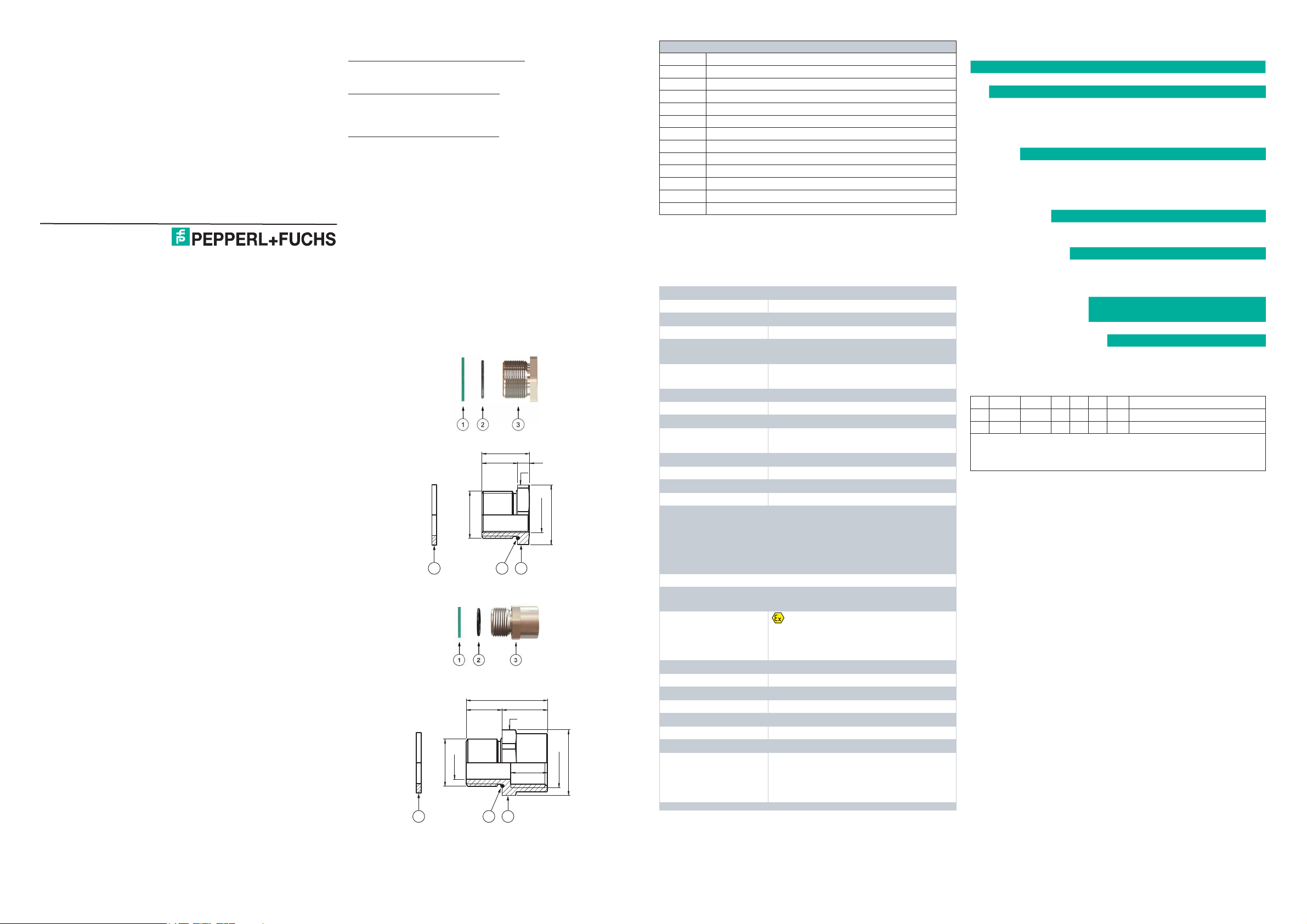
Dimensions and Assembly
TD
1 32
DI
TD
1 32
L
HTL
SW
TF
D2
L
HTL
SW
TF
TLF
D2
Legend - details and values see data table
1 Washer gasket (accessory)
2 O-Ring
3 Adapter
DI Diameter thru-hole
D2 Width across corners
H Length outside enclosure
SW Width across fl ats
TD Thread size
TF Thread size female
TL Thread length
TLF Thread length female
L Total length
Tech nic al S pec ifi cations
General
Types and variants AD* - see type code table
Mechanical specifications
Dimensions see data tables
Thread type
Thread type female
Degree of protection IP66 / IP68
Mass see individual datasheets
Material
Adapter
Finish inherent color silver
O-Ring chloroprene / neoprene or silicone
Washer gasket aramid fibers bonded with NBR
Ambient conditions
Ambient temperature
Data for application in connection with hazardous areas
EU-Type Examination
Certificate
Marking
International approvals
IECEx approval IECEx CES 15.0006X
EAC approval TC RU C-TR.GB05.B.00918
CCOE approval PESO A/P/HQ/KA/104/5579 (P420366)
Conformity
Degree of protection EN 60529
CE marking 0102
Standards
metric ISO pitch 1.5 mm or NPT ANSI ASME
B1.20.1
metric ISO pitch 1.5 mm or NPT ANSI ASME
B1.20.1
brass nickel-plated or AISI 316 (1.4401)
stainless steel
chloroprene O-ring:
-40 ... 100 °C (-40 ... 212 °F)
silicone O-ring: -60 ... 130 °C (-76 ... 266 °F)
washer gasket: -40 ... 80 °C (-40 ... 176 °F)
Service temperature might be limited by the
use of O-rings or washer gaskets.
CESI 15ATEX029X
II 2 GD
Ex db IIC Gb
Ex eb IIC Gb
Ex tb IIIC Db
IEC/EN 60079-0: 2012
IEC/EN 60079-1: 2007
IEC/EN 60079-7: 2007
IEC/EN 60079-31: 2009
Type Code / Model Number
Series
AD adapters
|
Thread, male
| M*
| NPT*
||
|| M*
||NPT*
|| |
|| |BN brass nickel-plated
|| |SS stainless steel
|| ||
|| ||C chloroprene / neoprene
|| ||S silicone
|| ||X no seal
|| |||
|| |||** length in mm
|| ||||
|| ||||
|| ||||K** units quantity per package
AD .xx .xx .xx .x .nn .Knn
AD .M50 .NPT2 .BN .C .18 .K01 Example
Example: Adapter, male thread size M50, female thread size NPT 2", body
brass nickel-plated, O-Ring chloroprene, installation thread length 18 mm,
one piece
male thread metric ISO pitch 1.5; sizes see dimensions data
table
male thread NPT ANSI ASME B1.20.1; sizes see dimensions
data table
Thread, female
male thread metric ISO pitch 1.5; sizes see dimensions
data table
NPT ANSI ASME B1.20.1; sizes see dimensions data
table
Material
Material Seals / O-Ring
Thread length for installation in
enclosure
Packaging unit
units not packaged, for use
in Pepperl+Fuchs Solution
Engineering Centers
Page 2

Variant-Specifi c Data Metric-Metric
Thread Male Thread Female Dimensions [mm]
Type
AD.M20.M16.*.*.15.* M20 15 M16 19 4 19 27.5 25 6
AD.M25.M20.*.*.15.* M25 15 M20 19 4 19 33 30 8.5
AD.M32.M20.*.*.15.* M32 15 M20 19 4 19 39.5 36 9
AD.M32.M25.*.*.15.* M32 15 M25 19 4 19 39.5 36 9
AD.M40.M32.*.*.18.* M40 18 M32 22 4 22 50 45 9.5
AD.M50.M40.*.*.18.* M50 18 M40 23 5 23 61 55 10
AD.M63.M50.*.*.18.* M63 18 M50 23 5 23 77 70 10.5
TD
TL
[mm]
TF
TLF
[mm]
H L D2 SW SW
Nut torques
[Nm]
Variant-Specifi c Data NPT-Metric
TL
Thread
Female
TF
TLF
[mm]
Dimensions [mm]
H L DI D2 SW SW
Thread Male
Type
TD
AD.NPT1/2.M20.*.*.15.* NPT 1/2'' 15 M20 15 19 34 14.5 27.5 25 8
AD.NPT3/4.M20.*.*.15.* NPT 3/4'' 15 M20 19 4 19 - 33 30 9
AD.NPT3/4.M25.*.*.15.* NPT 3/4'' 15 M25 15 19 34 19 33 30 9
AD.NPT3/4.M32.*.*.15.* NPT 3/4'' 15 M32 15 19 34 19 39.5 36 9
AD.NPT1.M32.*.*.15.* NPT 1'' 15 M32 15 19 34 26 39.5 36 11
AD.NPT1.M40.*.*.15.* NPT 1'' 15 M40 18 22 37 26 50 45 11
AD.NPT1-1/4.M40.*.*.18.* NPT 1-1/4'' 18 M40 18 22 40 35 50 45 13
AD.NPT1-1/2.M50.*.*.18.* NPT 1-1/2'' 18 M50 18 22 40 40 61 55 15
AD.NPT2.M75.*.*.18.* NPT 2'' 18 M75 18 22.5 40.5 51 88.5 80 18
[mm]
Nut torques
[Nm]
Variant-Specifi c Data Metric-NPT
Thread Male Thread Female Dimensions [mm]
Type
AD.M20.NPT1/2.*.*.15.* M20 15 NPT 1/2'' 15 19 34 14 27.5 25 6
AD.M20.NPT3/4.*.*.15.* M20 15 NPT 3/4'' 15 19 34 14 33 30 6
AD.M25.NPT1/2.*.*.15.* M25 15 NPT 1/2'' 19 4 19 - 33 30 8.5
AD.M25.NPT3/4.*.*.15.* M25 15 NPT 3/4'' 15 19 34 19 33 30 8.5
AD.M25.NPT1.*.*.15.* M25 15 NPT 1'' 15 19 34 19 39.5 36 8.5
AD.M32.NPT3/4.*.*.15.* M32 15 NPT 3/4'' 19 4 19 - 39.5 36 9
AD.M32.NPT1.*.*.15.* M32 15 NPT 1'' 15 19 34 26 39.5 36 9
AD.M40.NPT1-1/4.*.*.18.* M40 18 NPT 1-1/4'' 18 22 40 34 50 45 9.5
AD.M40.NPT1-1/2.*.*.18.* M40 18 NPT 1-1/2'' 18 22 40 34 61 55 9.5
AD.M50.NPT1-1/2.*.*.18.* M50 18 NPT 1-1/2'' 18 22 40 40 61 55 10
AD.M50.NPT2.*.*.18.* M50 18 NPT 2'' 18 22.5 40.5 44 72 65 10
AD.M63.NPT2.*.*.18.* M63 18 NPT 2'' 18 22.5 40.5 51 75 68 10.5
TD
TL
[mm]
TF
TLF
[mm]
H L DI D2 SW SW
Nut torques
[Nm]
 Loading...