

Page 1
FACTORY AUTOMATION
MANUAL
Absolute Rotary Encoder
with CANopen Interface
Page 2

Absolute Rotary Encoder
With regard to the supply of products, the current issue of the following document is ap-
plicable: The General Terms of Delivery for Products and Services of the Electrical Indus-
try, published by the Central Association of the Electrical Industry (Zentralverband
Elektrotechnik und Elektroindustrie (ZVEI) e.V.) in its most recent version as well as the
supplementary clause: "Expanded reservation of proprietorship"
Page 3

Absolute Rotary Encoder
1 Introduction................................................................................. 8
1.1 Content of this Document ................................................................... 8
1.2 Target Group, Personnel...................................................................... 8
1.3 Symbols Used ...................................................................................... 8
2 Declaration of conformity ........................................................ 10
2.1 CE conformity..................................................................................... 10
3 Safety ......................................................................................... 11
3.1 Symbols relevant to safety................................................................ 11
3.2 Intended Use ...................................................................................... 11
3.3 General safety instructions ............................................................... 11
4 General Information on System Integration ........................... 12
4.1 Using this Manual .............................................................................. 12
4.2 General CANopen Information .......................................................... 12
5 Installation of Photoelectric Absolute Rotary Encoder ........ 14
5.1 Signal Assignment of Terminal Block .............................................. 14
5.2 Signal Assignment of Connector and Cable Variants .................... 16
5.3 Activation of the Terminator.............................................................. 17
5.4 Installation Hints for Cabling ............................................................ 17
5.5 Setting of Node Number and Baud Rate in the Bus Cover ............ 17
5.6 Status of the Bus Cover LEDs........................................................... 19
6 Installation of Magnetic Absolute Rotary Encoder ............... 21
6.1 Signal Assignment of Connector and Cable Variants .................... 21
6.2 Activation of Terminator .................................................................... 21
6.3 Setting of Node Number and Baud Rate.......................................... 21
6.4 Status of the LEDs.............................................................................. 22
3
Page 4

Absolute Rotary Encoder
7 Quick Start Guide ..................................................................... 23
7.1 Configure the Absolute Rotary Encoder for Integration
into a CAN Network ............................................................................ 23
7.2 Configure application-specific encoder Parameters ...................... 25
8 Configuration ............................................................................ 29
8.1 Operating Modes ................................................................................ 29
8.1.1 General............................................................................................. 29
8.1.2 Mode: Pre-operational...................................................................... 29
8.1.3 Mode: Start - Operational ................................................................. 29
8.1.4 Mode: Stopped................................................................................. 29
8.1.5 Reinitialization of the Rotary Encoder............................................... 29
8.2 Normal Operating ............................................................................... 30
8.3 Storing Parameter............................................................................... 31
8.3.1 List of storable Parameters............................................................... 31
8.3.2 Storing Procedure ............................................................................ 31
8.4 Restoring Parameters ........................................................................ 32
8.5 Usage of Layer Setting Services (LSS) ............................................32
9 Programmable Parameters...................................................... 34
9.1 Programming example: Preset Value ...............................................35
9.1.1 Set Encoder Preset Value................................................................. 35
9.2 Communication Profile DS301 specific objects
from 1000h – 1FFFh ........................................................................... 36
9.3 Manufacturer specific objects from 2000h – 5FFFh........................ 37
9.4 Application specific objects from 6000h – 67FEh........................... 38
4
Page 5

Absolute Rotary Encoder
9.5 Object Descriptions ........................................................................... 39
9.5.1 Object 1000h: Device Type .............................................................. 39
9.5.2 Object 1001h: Error Register ........................................................... 39
9.5.3 Object 1003h: Pre-Defined Error Field ............................................. 39
9.5.4 Object 1005h: COB-ID Sync............................................................ 40
9.5.5 Object 1008h: Manufacturer Device Name ...................................... 40
9.5.6 Object 1009h: Manufacturer Hardware Version ............................... 40
9.5.7 Object 100Ah: Manufacturer Software Version ................................ 40
9.5.8 Object 100Ch: Guard Time .............................................................. 41
9.5.9 Object 100Dh: Life Time Factor ....................................................... 41
9.5.10 Object 1010h: Store Parameters ...................................................... 41
9.5.11 Object 1011h: Restore Parameters.................................................. 41
9.5.12 Object 1012h: COB-ID Time Stamp Object...................................... 42
9.5.13 Object 1013h: High Resolution Time Stamp .................................... 42
9.5.14 Object 1014h: COB-ID Emergency Object....................................... 42
9.5.15 Object 1016h: Consumer Heartbeat Time ....................................... 42
9.5.16 Object 1017h: Producer Heartbeat Time ......................................... 43
9.5.17 Object 1018h: Identity Object .......................................................... 43
9.5.18 Object 1020h: Verify Configuration .................................................. 43
9.5.19 Object 1029h: Error Behavior........................................................... 43
9.5.20 Object 1800h: 1st Transmit PDO Communication Parameter........... 44
9.5.21 Object 1801h: 2nd Transmit PDO Communication Parameter ......... 44
9.5.22 Object 1A00h: 1st Transmit PDO Mapping Parameter ..................... 45
9.5.23 Object 1A01h: 2nd Transmit PDO Mapping Parameter .................... 45
9.5.24 Object 1F50h: Download Program Area .......................................... 46
9.5.25 Object 2000h: Position Value ........................................................... 46
9.5.26 Object 2100h: Operating Parameters............................................... 46
9.5.27 Object 2101h: Resolution per Revolution......................................... 47
9.5.28 Object 2102h: Total Resolution ........................................................ 47
9.5.29 Object 2
103h: Preset Value ............................................................. 48
9.5.30 Object 2104h: Limit Switch, min....................................................... 48
9.5.31 Object 2105h: Limit Switch, max...................................................... 48
9.5.32 Object 2160h: Customer Storage..................................................... 49
9.5.33 Object 2200h: Cyclic Timer PDO ..................................................... 49
9.5.34 Object 2300h: Save Parameter with Reset....................................... 49
9.5.35 Object 2600h: High-Resolution Postion Value ................................. 50
9.5.36 Object 3000h: Node Number ........................................................... 50
9.5.37 Object 3001h: Baud Rate................................................................. 51
5
Page 6

Absolute Rotary Encoder
9.5.38 Object 3002h: Terminator ................................................................. 51
9.5.39 Object 3003h: Auto Baud Detection ................................................. 51
9.5.40 Object 3005h: Auto Boot up ............................................................. 52
9.5.41 Object 3010h: Speed Control ........................................................... 53
9.5.42 Object 3011h: Speed Value.............................................................. 53
9.5.43 Object 3020h: Acceleration Control.................................................. 53
9.5.44 Object 3021h: Acceleration Control.................................................. 53
9.5.45 Object 3030h: Backward Compatible Mode ..................................... 54
9.5.46 Object 3040h: Life Cycle Counter..................................................... 55
9.5.47 Object 3050h: Time Stamp Position Value........................................ 55
9.5.48 Object 4000h: Bootloader Control .................................................... 55
9.5.49 Object 4010h: PPR Incremental Encoder......................................... 56
9.5.50 Object 4020h: A/B Phase Shift ......................................................... 56
9.5.51 Object 6000h: Operating Parameters ............................................... 56
9.5.52 Object 6001h: Measuring Units per Revolution ................................ 57
9.5.53 Object 6002h: Total Measuring Range in Measuring Units ............... 57
9.5.54 Object 6003h: Preset Value.............................................................. 57
9.5.55 Object 6004h: Position Value ........................................................... 57
9.5.56 Object 6008h: High Resolution Position Value ................................. 58
9.5.57 Object 6030h: Speed Value.............................................................. 58
9.5.58 Object 6040h: Acceleration Value .................................................... 59
9.5.59 Object 6200h: Cyclic Timer .............................................................. 59
9.5.60 Object 6300h: Cam State Register ................................................... 60
9.5.61 Object 6301h: Cam Enable Register ................................................ 60
9.5.62 Object 6302h: Cam Polarity Register................................................ 60
9.5.63 Object 6400h: Area State Register ................................................... 63
9.5.64 Object 6401h: Work Area Low Limit ................................................. 63
9.5.65 Object 6402h: Work Area High Limit ................................................ 64
9.5.66 Object 6500h: Operating Status ....................................................... 64
9.5.67 Object 6501h: Singleturn Resolution ................................................ 64
9.5.68 Object 6502h: Number of Distinguishable Revolutions..................... 64
9.5.69 Object 6503h: Alarms....................................................................... 65
9.5.70 Object 6504h: Supported Alarms ..................................................... 65
9.5.71 Object 6505h: Warnings................................................................... 65
9.5.72 Object 6506h: Supported warnings .................................................. 66
9.5.73 Object 6507h: Profile and Software Version ..................................... 66
9.5.74 Object 6508h: Operating Time ......................................................... 67
9.5.75 Object 6509h: Offset Value............................................................... 67
6
Page 7

Absolute Rotary Encoder
9.5.76 Object 6509h: Module identification................................................. 67
9.5.77 Object 650Bh: Serial Number .......................................................... 67
10 Troubleshooting........................................................................ 68
10.1 What to Do in Case of a Fault............................................................ 68
7
Page 8

Absolute Rotary Encoder
Introduction
1Introduction
1.1 Content of this Document
This document contains information that you need in order to use your product throughout the
applicable stages of the product life cycle. These can include the following:
■
Product identification
■
Delivery, transport, and storage
■
Mounting and installation
■
Commissioning and operation
■
Maintenance and repair
■
Troubleshooting
■
Dismounting
■
Disposal
Note!
For full information on the product, refer to the further documentation on the Internet at
www.pepperl-fuchs.com.
The documentation consists of the following parts:
■
Present document
■
Datasheet
Additionally, the following parts may belong to the documentation, if applicable:
■
EU-type examination certificate
■
EU declaration of conformity
■
Attestation of conformity
■
Certificates
■
Control drawings
■
Additional documents
1.2 Target Group, Personnel
Responsibility for planning, assembly, commissioning, operation, maintenance, and
dismounting lies with the plant operator.
Only appropriately trained and qualified personnel may carry out mounting, installation,
commissioning, operation, maintenance, and dismounting of the product. The personnel must
have read and understood the instruction manual and the further documentation.
Prior to using the product make yourself familiar with it. Read the document carefully.
1.3 Symbols Used
This document contains symbols for the identification of warning messages and of informative
messages.
Warning Messages
You will find warning messages, whenever dangers may arise from your actions. It is mandatory
that you observe these warning messages for your personal safety and in order to avoid
property damage.
Depending on the risk level, the warning messages are displayed in descending order as
follows:
2017-04
8
Page 9

Absolute Rotary Encoder
Introduction
Danger!
This symbol indicates an imminent danger.
Non-observance will result in personal injury or death.
Warning!
This symbol indicates a possible fault or danger.
Non-observance may cause personal injury or serious property damage.
Caution!
This symbol indicates a possible fault.
Non-observance could interrupt the device and any connected systems and plants, or result in
their complete failure.
Informative Symbols
Note!
This symbol brings important information to your attention.
Action
This symbol indicates a paragraph with instructions. You are prompted to perform an action or
a sequence of actions.
2017-04
9
Page 10

Absolute Rotary Encoder
Declaration of conformity
2 Declaration of conformity
2.1 CE conformity
This product was developed and manufactured under observance of the applicable European
standards and guidelines.
Note!
A declaration of conformity can be requested from the manufacturer.
10
2017-04
Page 11

Absolute Rotary Encoder
Safety
3Safety
3.1 Symbols relevant to safety
Danger!
This symbol indicates an imminent danger.
Non-observance will result in personal injury or death.
Warning!
This symbol indicates a possible fault or danger.
Non-observance may cause personal injury or serious property damage.
Caution!
This symbol indicates a possible fault.
Non-observance could interrupt the device and any connected systems and plants, or result in
their complete failure.
3.2 Intended Use
Absolute rotary encoders detect the rotation angle -and, in the case of a multiturn absolute
rotary encoder, the revolutions of the rotary encoder shaft- with high precision and resolution.
The absolute position value derived from this is provided by the rotary encoder via the
CANopen interface in accordance with the standard DS406. The rotary encoder is to be
integrated into a CANopen network and should be used only in this way. Typical applications
include positioning tasks and length measurement, for example for cranes, construction
machinery, elevators, and packaging machines.
Read through these instructions thoroughly. Familiarize yourself with the device before
installing, mounting, or operating.
Always operate the device as described in these instructions to ensure that the device and
connected systems function correctly. The protection of operating personnel and plant is only
guaranteed if the device is operated in accordance with its intended use.
3.3 General safety instructions
Responsibility for planning, assembly, commissioning, operation, maintenance, and
dismounting lies with the plant operator.
Installation and commissioning of all devices may only be performed by trained and qualified
personnel.
User modification and or repair are dangerous and will void the warranty and exclude the
manufacturer from any liability. If serious faults occur, stop using the device. Secure the device
against inadvertent operation. In the event of repairs, return the device to your local
Pepperl+Fuchs representative or sales office.
Note!
Disposal
Electronic waste is hazardous waste. When disposing of the equipment, observe the current
statutory requirements in the respective country of use, as well as local regulations.
2017-04
11
Page 12

Absolute Rotary Encoder
General Information on System Integration
4 General Information on System Integration
4.1 Using this Manual
This manual explains how to install and configure the photoelectric and magnetic absolute
rotary encoders with CANopen interface applicable for industrial applications with CANopen
interface.
Magnetic absolute rotary encoders are fully compliant with standard DS406.
Photoelectric absolute rotary encoders are fully compliant with following CiA standards:
■
DS301V402 CANopen Application Layer
■
DR303-1 Cabeling and connector pin assignment
■
DR303-3 CANopen indicator specification
■
DS305V200 CANopen Layer Setting Service
■
DS306V1R3 Electronic datasheet specification
■
DS406V32 Device Profile for Encoders
Measuring System for Photoelectric Absolute Rotary Encoders
The measuring system consists of a light source, a code disc pivoted in a precision ball bearing
and an opto-electronic scanning device. A LED is used as a light source which shines through
the code disc and onto the screen behind. The tracks on the code disk are evaluated by an
optoarray behind the reticle.
With every position another combination of slashes in the reticle is covered by the dark spots
on the code disk and the light beam on the photo transistor is interrupted. That way the code on
the disc is transformed into electronic signals. Fluctuations in the intensity of the light source
are measured by an additional photo transistor and another electronic circuit compensates for
these. After amplification and conversion the electronic signals are available for evaluation.
Measuring System for Magnetic Absolute Rotary Encoders
Magnetic rotary encoder determine positions using the Hall effect sensor technology
developed for the automotive mass market. A permanent magnet fixed to the shaft generates a
magnetic field that is sampled by the Hall sensor, which translates the measured value into a
unique absolute position value.
To register revolutions even when no voltage is applied, energy from the turning of the shaft
must suffice for proper operation. An innovative, patented technology makes this feasible even
at low rotational speeds and through long standstill periods – a Wiegand wire ensures that the
magnetic field can only follow the turning of the shaft in discrete steps. A coil wound on the
Wiegand wire receives only brief, strong voltage spikes, which prompt the reliable recognition
of each revolution.
Note!
Further information on technical data, mechanical data, connection layouts, and available
connection lines for the relevant absolute rotary encoder types can be found in the
corresponding datasheet.
4.2 General CANopen Information
CANopen system is used in industrial applications. It is a multiple access system (maximum:
127 participants), which means that all devices can access the bus. In simple terms, each
device checks whether the bus is free, and if it is the device is able to send messages. If two
devices try to access the bus at the same time, the device with the higher priority level (lowest
ID number) has permission to send its message.
12
2017-04
Page 13

Absolute Rotary Encoder
General Information on System Integration
Devices with the lowest priority level must delay their data transfer and wait before retrying to
send their message. Data communication is carried out via messages. These messages
consist of 1 COB-ID followed by a maximum of 8 bytes of data. The COB-ID, which determines
the priority of the message, consists of a function code and a node number. The node number
corresponds to the network address of the device. It is unique on a bus. The function code
varies according to the type of message being sent:
■
Management messages (LMT, NMT)
■
Messaging and service (SDOs)
■
Data exchange (PDOs)
■
Layer Setting Services (LSS)
■
Predefined messages (synchronization, emergency messages)
The absolute rotary encoder supports the following operating modes:
■
Polled mode: The position value is only sent on request.
■
Cyclic mode: The position value is sent cyclically (regular, adjustable interval) on the bus.
■
SYNC mode: The position value is sent after a synchronization message (SYNC) is
received. The position value is sent every n SYNCs (n . 1).
Other functions (offset values, resolution, etc) can be configured. The absolute rotary encoder
corresponds to the class 2 encoder profile (DS 406 in which the characteristics of encoder with
CANopen interface are defined). The node number and speed in bauds are determined by
their corresponding object dictionary entries.
The transmission speed can range from 20 kBaud up to 1Mbaud (30 m cable for a maximum
speed of 1Mbaud, 1000 m cable for a maximum speed of 20 kbaud). Various software tools for
configuration and parameter-setting are available from different suppliers. It is easy to align and
program the rotary encoders using the EDS (electronic data sheet) configuration file provided
on the Pepperp+Fuchs internet page www.pepperl-fuchs.com
Further Information is available at:
CAN in Automation (CiA) International Users and Manufacturers Group e.V.
Kontumazgarten 3
DE-90429 Nurenberg
(*) Reference: CAN Application Layer for Industrial Applications
CAL-based Communication Profile for Industrial Systems
■
CiA Draft Standard 301
■
CiA Draft Standard 305 Layer Setting Services
■
CiA Draft Standard 406 Device Profile for Encoders
Note!
All datasheets and manuals can be downloaded for free from our website www.pepperlfuchs.com
We do not assume responsibility for technical inaccuracies or omissions. Specifications are
subject Note to change without notice.
2017-04
13
Page 14
Absolute Rotary Encoder
ON
T
G
H-+G
x10Bd
x1
LLH
8
7
2
6
5
4
3
0
9 1
8
7
2
6
5
4
3
0
9 1
8
7
2
6
5
4
3
0
9 1
R
Te r m i n a t o r
Bus In
Bus Out
RS 485 Interface
Installation of Photoelectric Absolute Rotary Encoder
5 Installation of Photoelectric Absolute Rotary Encoder
The following chapter describes all aspects helpful for installation of photoelectric absolute
rotary encoders with bus cover. Depending on the rotary encoder model there are the following
connection variants:
■
Rotary encoder with bus cover equipped with cable glands
■
Rotary encoder with bus cover equipped with a cable exit
■
Rotary encoder with bus cover equipped with one or two M12x1 connectors, 5-pin
Bus cover features like node number adressing, baud rate setting and activation of termination
resistor are identical for all these variants.
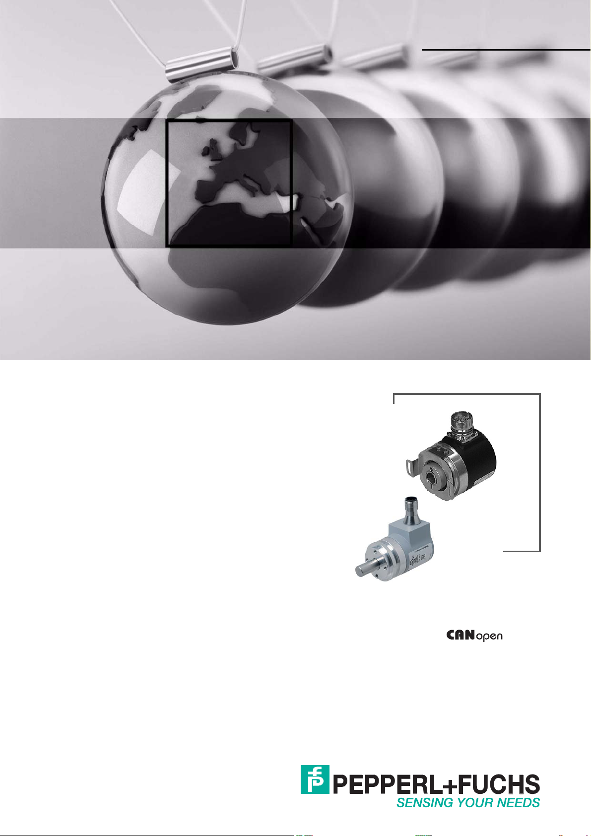
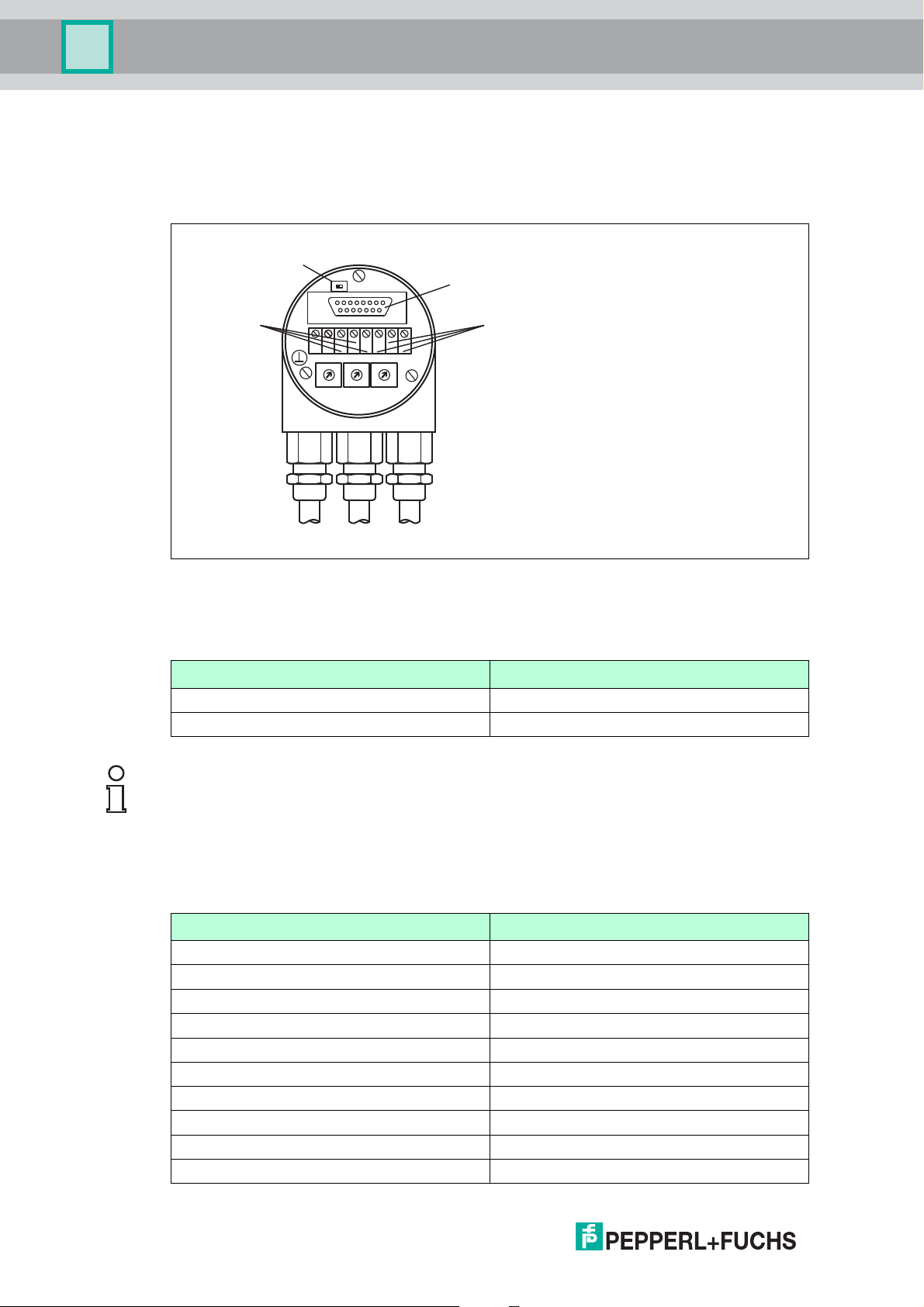
5.1 Signal Assignment of Terminal Block
The rotary encoder is connected with two or three cables depending on whether the power
supply is integrated into the bus cable or connected separately. If the power supply is
integrated into the bus cable, one of the cable glands can be fitted with a plug. The cable
glands are suitable for cable diameters from 6.5 up to 9 mm.
14
Figure 5.1
Te r m i na l Description
Ground
+ 24 V Supply Voltage
- 0 V Supply Voltage
G CAN Ground
L CAN Low (Bus In)
H CAN High (Bus In)
G* CAN Ground
L* CAN Low (Bus Out)
H* CAN High (Bus Out)
Table 5.1 * are not connected, if terminator is ON
2017-04
Page 15

Absolute Rotary Encoder
Installation of Photoelectric Absolute Rotary Encoder
Bus Connection
The bus cover fulfills the function of a T-coupler. From there the wiring must be done according
to figure you find before. Please note the assignment of incoming and outgoing bus signals.
Caution!
Activated bus termination separates "Bus in" and "Bus out"
Non-observance of separation of "Bus in" and "Bus out" causes interferences on the CANopen
bus.
If you activate the bus termination on the rotary encoder ensure that the rotary encoder is the
last CANopen bus participant in the bus line.
2017-04
15
Page 16
Absolute Rotary Encoder
ON
T
G
H-+G
x10Bd
x1
LLH
8
7
2
6
5
4
3
0
9 1
8
7
2
6
5
4
3
0
9 1
8
7
2
6
5
4
3
0
9 1
R
Te r m i n a t o r
Bus In
Bus Out
RS 485 Interface
1
3
4
5
2
1
5
3
2
4
Installation of Photoelectric Absolute Rotary Encoder
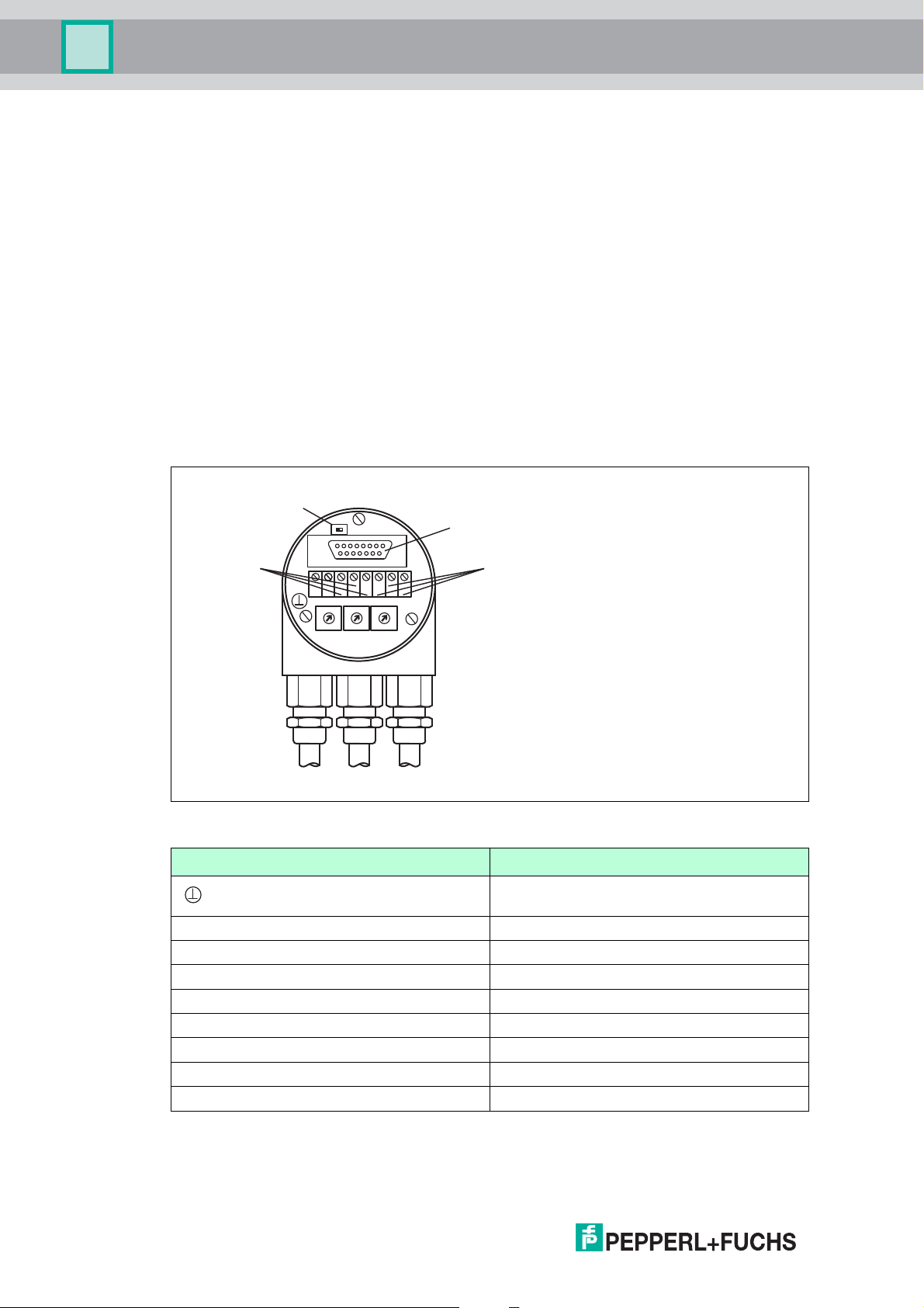
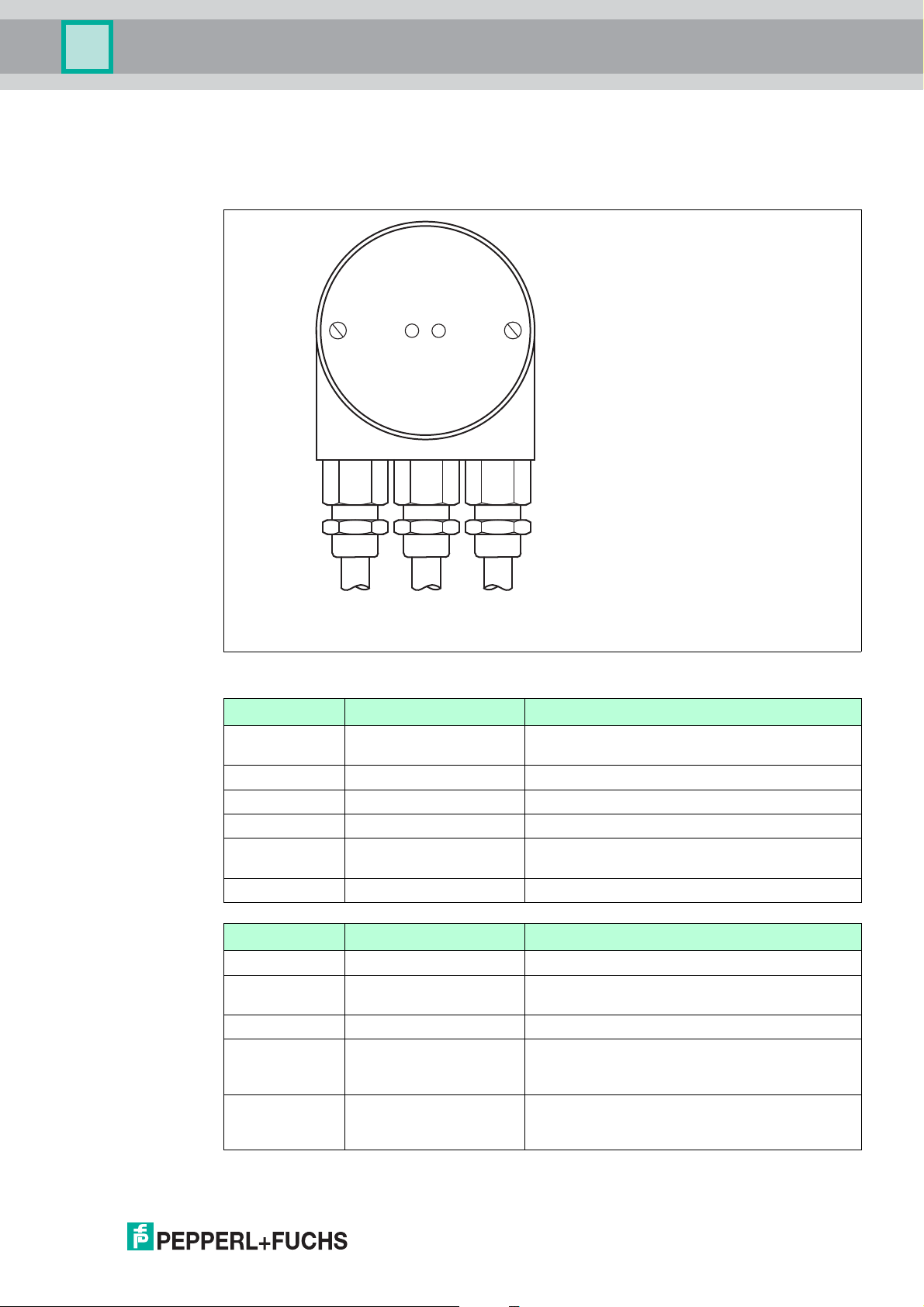
5.2 Signal Assignment of Connector and Cable Variants
The rotary encoders with cable- and connector-exit were designed in accordance to CiA
normative DR303-1 cabeling and connector pin assignment. They also have a removable bus
cover with all possibilities to set node number, baud rate and acitvate terminator.
Figure 5.2
The following table shows an assignment of the different connecting types (cable, connectors)
to the terminals of the bus cover.
Te r m i na l Description Cable M12 plug, 5-pin M12 socket, 5-pin
(-) - Power supply 1 3 3
(+) + Power supply 2 2 2
L CAN Low (Bus In) 3 5
H CAN High (Bus In) 4 4
G CAN Ground 5 1
L* CAN Low (Bus Out) 6 5
H* CAN High (Bus Out) 7 4
G* CAN Ground 8 1
Ground connection of
encoder housing
Table 5.2 * are not connected, if terminator is ON
green/
yellow
2017-04
16
Page 17
Absolute Rotary Encoder
Installation of Photoelectric Absolute Rotary Encoder
Caution!
Activated bus termination separates "Bus in" and "Bus out".
Non-observance of separation of "Bus in" and "Bus out" causes interferences on the CANopen
bus.
If you activate the bus termination on the rotary encoder ensure that the rotary encoder is the
last CANopen bus participant in the bus line.
5.3 Activation of the Terminator
There is a terminator provided in the bus cover, which must be used as a line termination on the
last device. The terminator is switched on when the switch is in the "ON position" (see figure
before).
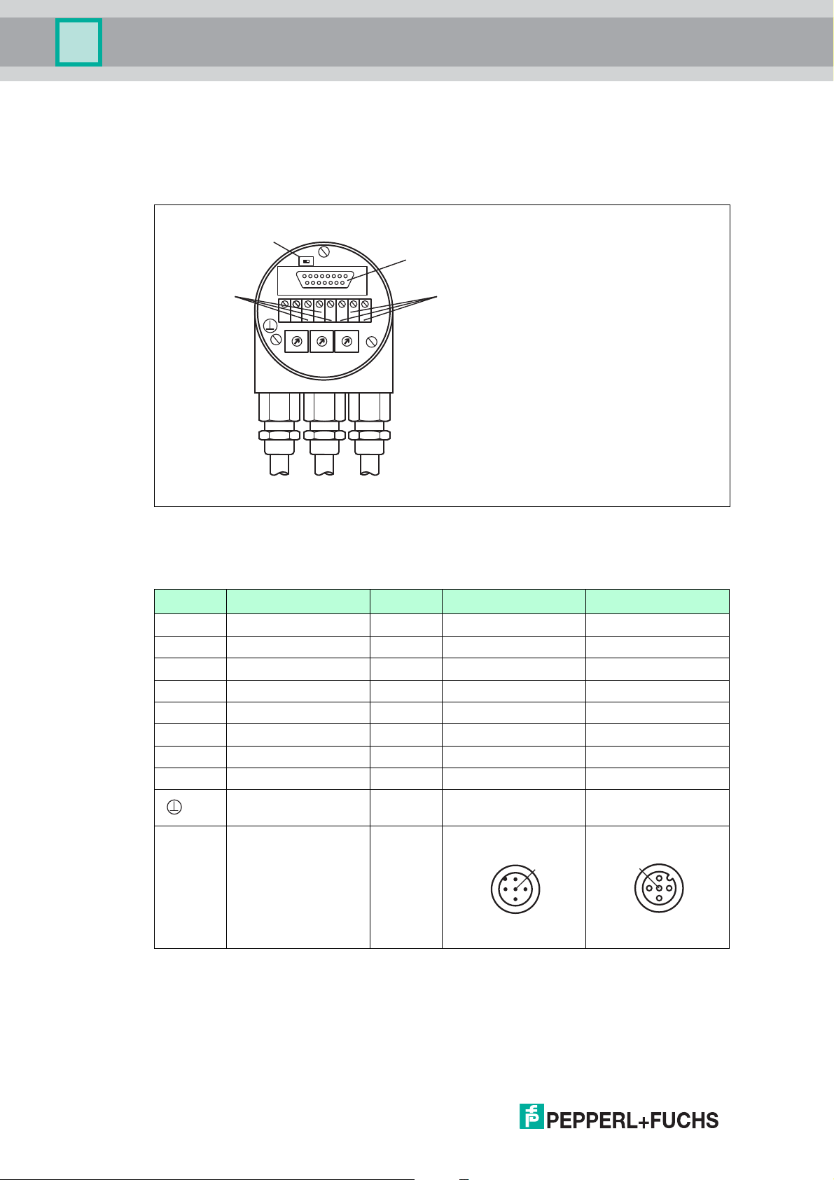
5.4 Installation Hints for Cabling
Cable Connection with Cable Gland
1. Remove screw, sealing and cone from the cable gland.
Figure 5.3
2. Remove 55 mm of the sheath and 50 mm of the shielding. About 5 mm of the wires should
be de-isolated.
3. Put screw and sealing on the cable.
4. The cone should be mounted under the shielding according to the figure before. Put the
whole cable into the cable gland and tighten the screw.
Minimization of Signal Interferences
Both the cable shielding and the metal housings of rotary encoders and subsequent
electronics have a shielding function. The housing must have the same potential and be
connected to the main signal ground over the machine chassis or by means of a separate
potential compensating line. Potential compensating lines should have a minimum cross
section of 6 mm
Do not lay signal cable in the direct vicinity of interference sources (air clearance > 100 mm (4
in.))
A minimum spacing of 200 mm (8 in.) to inductors is usually required, for example in switchmode power supplies.
Configure the signal lines for minimum length and avoid the use of intermediate terminals.
Shielded fieldbus cables shall be used! The shield must be grounded according to EMI rules!
In metal cable ducts, sufficient decoupling of signal lines from interference signal transmitting
cable can usually be achieved with a grounded partition.
2
.
5.5 Setting of Node Number and Baud Rate in the Bus Cover
Note!
Setting of node number and baud rate has to be done via software if Bd rotary switch is set to 9.
SDO objects and Layer Setting Services (LSS) are provided for this purpose.
2017-04
17
Page 18
Absolute Rotary Encoder
ON
T
G
H-+G
x10Bd
x1
LLH
8
7
2
6
5
4
3
0
9 1
8
7
2
6
5
4
3
0
9 1
8
7
2
6
5
4
3
0
9 1
R
Te r m i n a t o r
Bus In
Bus Out
RS 485 Interface
Installation of Photoelectric Absolute Rotary Encoder
Setting Node Number
The setting of the node number is done by turning the BCD coded rotary switches x10 and x1
in the bus cover. Possible (valid) addresses lie between 0 and 89 whereby every address can
only be used once.
Figure 5.4
Possible device address 0 ... 89.
Addresses 90 ... 99 are reserved.
BCD coded rotary switch Description
x1 single digits of address
X10 tens of address
Note!
Internally the CANopen rotary encoder adds 1 to the adjusted device address.
Setting Baud Rate
The setting of the baud rate is done by turning the Bd rotary switch in the bus cover. The
following baud rates are possible:
BCD coded rotary switch Baudrate in kBit/s
0 20
1 50
2 100
3 125
4 250
5 500
6 800
7 1000
8 reserved
9 Sets SDO and LSS mode
2017-04
18
Page 19
Absolute Rotary Encoder
Installation of Photoelectric Absolute Rotary Encoder
5.6 Status of the Bus Cover LEDs
The LED behaviour was designed in accordance to the CiA normative DR 303-3 CANopen
indicator specification.
Figure 5.5
CAN Run LED State Description
Flickering AutoBitrate / LSS Auto-bitrate detection is in progress or LSS
Blinking PRE-OPERATIONAL The encoder is in state PRE-OPERATIONAL
Single flash STOPPED The encoder is in state STOPPED
Double flash reserved
Triple flash Program / Firmware
download
On OPERATIONAL The encoder is in state OPERATIONAL
Err LED State Description
Off No error The encoder is in working condition
Flickering AutoBitrate / LSS Auto-bitrate detection is in progress or LSS
Blinking Invalid configuration General configuration error
Single flash Warning limit reached At least one of the error counters of the CAN
Double flash Error control event A guard event (NMT-slave or NMT-master) or a
services are in progress
A software download is running on the encoder
services are in progress
controller has reached or exceeded the warning
level (too many error frames)
heartbeat event (heartbeat consumer) has
occured
2017-04
19
Page 20

Absolute Rotary Encoder
Installation of Photoelectric Absolute Rotary Encoder
Err LED State Description
Tri pl e fl as h Sync. error The sync. message has not been received within
Quadruple flash Error, event-timer An expected PDO has not been received before
On Bus off The CAN controller is bus off
the configured communication cycle period time
out (see objekt 1006h)
the even-timer elapsed
20
2017-04
Page 21
Absolute Rotary Encoder
1
3
4
5
2
Installation of Magnetic Absolute Rotary Encoder
6 Installation of Magnetic Absolute Rotary Encoder
The following chapter describes all aspects helpful for installation of magnetic absolute rotary
encoders. Depending on the rotary encoder model there are the following connection variants:
■
Rotary encoder with a cable exit
■
Rotary encoder with two M12x1 connectors, 5-pin
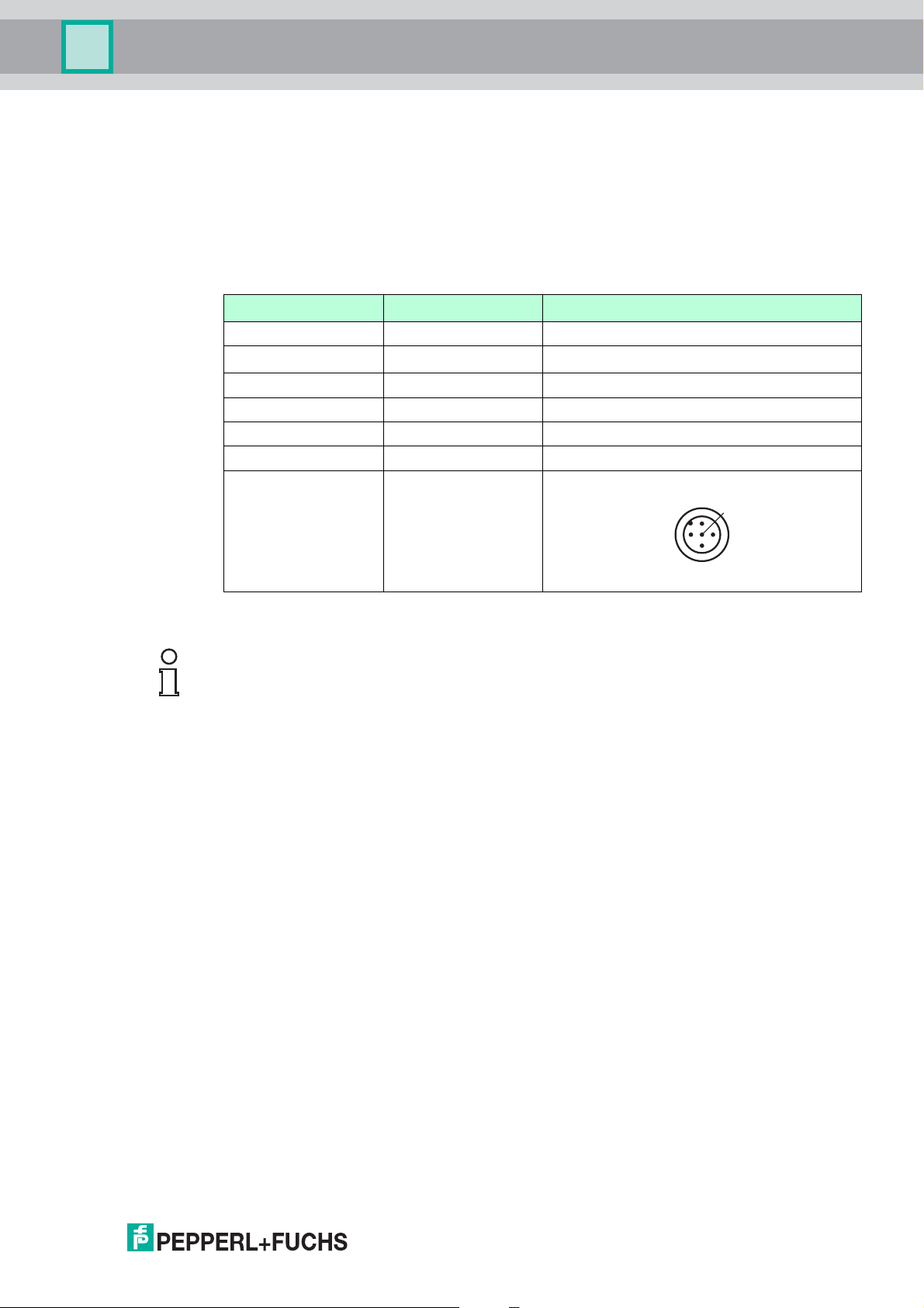
6.1 Signal Assignment of Connector and Cable Variants
Signal Wire end 5-pin, M12 x 1 connector
CAN GND green 1
+U
b
GND yellow 3
CAN-High white 4
CAN-Low brown 5
Shielding Shielding Housing
Pinout
red 2
6.2 Activation of Terminator
Note!
The magnetic absolute rotary encoder is equipped with an internal terminator, which can be
used as a line termination. Be aware, that the terminator is only activated, when the encoder is
powered, because the microcontroller is internally needed to switch on the terminator.
If the rotary encoder is connected at the end or beginning of the bus using of the internal
terminator is possible by parameterization of SDO object "3002 h" The internal terminator is
acitvated by writing "01 h" into this object.
6.3 Setting of Node Number and Baud Rate
Setting of the node number and baud rate has to be done by parameterization of the relevant
SDO objects or via LSS. Some absolute rotary encoders are provided with auto baud detection
(see relevant datasheet).
Default values are:
■
Baud rate 125 kBaud
■
Node number 32 decimal (20 h)
Setting Node Number via SDO Objects
The node number has to be adjusted via SDO objects. To set the node number, object 3000h
has to be written. For further information regard chapter "Object Descriptions".
Setting Baud Rate via SDO Objects
The baud rate has to be adjusted via SDO objects, if auto baud feature is not activated or is not
possible to use because of network start-up behavior. To set baud rate object 3001h has to be
written. For further information regard chapter "Object Descriptions".
2017-04
21
Page 22

Absolute Rotary Encoder
Installation of Magnetic Absolute Rotary Encoder
Setting Node Number via LSS
The node number can also be adjusted via Layer Setting Services (LSS). For further
information regard chapter "Usage of Layer Setting Services (LSS)"
Setting Baud Rate via LSS
The baud rate can also be adjusted via Layer Setting Services (LSS). For further information
regard chapter "Usage of Layer Setting Services (LSS)"
6.4 Status of the LEDs
The magnetic absolute rotary encoders are equipped with a dual color LED.
CAN Run
(green)
Blinking PRE-OPERATIONAL Boot up message is sent, device configuration is
Single flash STOPPED The encoder is in CAN state STOPPED.
On OPERATIONAL The encoder is in CAN state OPERATIONAL.
Off No power supply
State Description
possible, encoder is in CAN state PREOPERATIONAL.
Err (red) State Description
Off No error The encoder is in operatring mode.
Flickering AutoBitrate Auto baud mode is active and the encoder tries
Single flash Warning limit reached At least one of the error counters of the CAN
Double flash Error control event A guard event (NTM slave or NTM master) or a
On Bus off The CAN controller is in sate bus off. No
to find within the time-out period a valid CAN
message for baud rate measurement.
controller has reached or exceeded the warning
level (too many error frames).
heartbeat event has occurred.
communication possible anymore. Too many
error frames in the network.
22
2017-04
Page 23

Absolute Rotary Encoder
Quick Start Guide
7Quick Start Guide
Intention of this chapter is to help the user getting a magnetic or photoelectric absolute rotary
encoder very easy and fast to operate. The user is still responsible to configure the absolute
rotary encoder in the right way and reading the whole manual carefully.
With the following sequence a normal procedure is described to configure a device for
standard applications. It shall guide you roughly through this process.
7.1 Configure the Absolute Rotary Encoder for Integration into a CAN Network
For this purpose you need to set up the node number and the baud rate first.
Depending on your absolute rotary encoder model there are different ways to do so.
■
Photoelectric absolute rotary encoder with bus cover: Setting is possible via BCD coded
rotary switches or if rotary switch Bd = 9 via SDO objects or Layer Setting Services (LSS).
■
Magnetic absolute rotary encoder: Default setting for node number is 32 decimal and
baud rate is 125 kBaud. If other settings are required setting is only possible via SDO
objects or Layer Setting Services (LSS). Some models have auto baud rate detection (see
relevant datasheet) which has to be checked if activated. If this feature is activated so only
node number has to be set.
Caution!
Check requirements of baud rate and node number of your network before configuration!
If your running network uses a different baud rate or the node number is already in use, then
you shall make a point-to-point connection to the encoder with a configuration tool to prevent a
crash of the different configured running network. If auto baud feature is used in the encoder it
simplifies installation.
First Steps of Configuration of a Magnetic Absolute Rotary Encoder
1. If the encoder has no active auto baud detection connect the encoder with a configuration
tool and set the baud rate to 125 kBd.
2. Power on the encoder.
You will see a boot up message in case of a trace tool is used. For devices equipped with
status LEDs a green colored LED is blinking to indicate the CAN state PREOPERATIONAL.
3. If necessary activate the terminator of the encoder by writing "01h" into object "3002 h".
4. Continue by reading and writing data into the relevant following objects in this chapter.
First Steps of Configuration of a Photoelectric Absolute Rotary Encoder
Note!
In case you want to set baud rate and node number via SDO objects rotary switch Bd has to be
in position 9.
1. Set the baud rate desired with rotary switch Bd (20 kBd factory default) and the node address you need with rotary switches x10 and x1 (32 factory default) . If Bd = 9 connect the
encoder with a configuration tool and set the baud rate desired.
2. Power on the encoder.
You will see a boot up message in case of a trace tool is used. For devices equipped with
status LEDs a green colored LED is blinking to indicate the CAN state PREOPERATIONAL.
2017-04
23
Page 24

Absolute Rotary Encoder
Quick Start Guide
3. If necessary activate the terminator of the encoder by setting the relevant switch in the bus
cover.
4. If "Bd = 9" continue by reading and writing data into the relevant following objects.
Message received from Encoder on Boot up
Identifier Service/Process data
NN = 20h Byte 0 Byte 1 Byte 2 Byte 3 Byte 4 Byte 5 Byte 6 Byte 7
700h + NN =
720h
Ta b le 7. 1
NN = node number of encoder
Configuration of Node Number
Object 3000h
Example:
00
Resulting node number = Value in object 3000h + 1h = Ah + 1h = Bh
The encoder itself adds the value 1 to the configured node number. This method is used to
prevent an identifier value of 0.
Message sent to Encoder
Identifier DLC Command Index Subindex Service/Process data
NN = 20h Download 3000h 00h Byte 4 Byte 5 Byte 6 Byte 7
600h + NN
= 620h
Ta b le 7. 2
Message received from Encoder
Identifier DLC Command Index Subindex Service/Process data
NN Download 3000h 00h Byte 4 Byte 5 Byte 6 Byte 7
580h + NN
= 5A0h
Ta b le 7. 3
8h 22h 00h 30h 00h 0Ah 00h 00h 00h
8h 60h 00h 30h 00h 00h 00h 00h 00h
Configuration of Baud Rate (only if auto baud feature is not used)
Object 3001h
Example: 500 kBd >> 05
24
Message sent to Encoder
Identifier DLC Command Index Subindex Service/Process data
NN = 20h Download 3001h 00h Byte 4 Byte 5 Byte 6 Byte 7
600h + NN
= 620h
Ta b le 7. 4
8h 22h 01h 30h 00h 05h 00h 00h 00h
2017-04
Page 25

Absolute Rotary Encoder
Quick Start Guide
Message received from Encoder
Identifier DLC Command Index Subindex Service/Process data
NN Download 3001h 00h Byte 4 Byte 5 Byte 6 Byte 7
580h + NN
= 5A0h
Ta b le 7. 5
Store Configuration
Object 1010h, Subindex 01
Signature "save" >> "73617665"
Message sent to Encoder
Identifier DLC Command Index Subindex Service/Process data
NN = 20h Download 1010h 00h Byte 4 Byte 5 Byte 6 Byte 7
600h + NN
= 620h
Ta b le 7. 6
8h 60h 01h 30h 00h 00h 00h 00h 00h
8h 22h 10h 10h 01h 73h 61h 76h 65h
Message received from Encoder
Identifier DLC Command Index Subindex Service/Process data
NN Download 1010h 01h Byte 4 Byte 5 Byte 6 Byte 7
580h + NN
= 5A0h
Ta b le 7. 7
The new network configuration of the encoder will be activated with a power cycle or NMT
reset.
8h 60h 10h 10h 01h 00h 00h 00h 00h
End of Configuration or further Configurations
Add the encoder to the network or go ahead with the configuration.
7.2 Configure application-specific encoder Parameters
For adaption of the encoder in your application you may use objects to configure the resolution
per revolution and the total resolution. Especially the preset value is relevant to adjust the
position value of the encoder to a desired value in the machine after mechanical installation. It
is useful to store the configuration in the device and not to re-configure the different parameters
after each power cycle or NMT reset. In the following tables the new configured node number is
assumed.
Configuration of Measuring Units per Revolution
Object 6001h
Example: 3600 dec >> 00000E10h
Explanation: The encoder will output 3600 steps per revolution that means 0.1° resolution.
2017-04
25
Page 26

Absolute Rotary Encoder
Quick Start Guide
Message sent to Encoder
Identifier DLC Command Index Subindex Service/Process data
NN = Bh Download 6001h 00h Byte 4 Byte 5 Byte 6 Byte 7
600h + NN
= 60Bh
Ta b le 7. 8
Message received from Encoder
Identifier DLC Command Index Subindex Service/Process data
NN Download 6001h 00h Byte 4 Byte 5 Byte 6 Byte 7
580h + NN
= 58Bh
Ta b le 7. 9
Configuration of total Measuring Range
8h 22h 01h 60h 00h 10h 0Eh 00h 00h
8h 60h 01h 60h 00h 00h 00h 00h 00h
Object 6002h
Example: 7200 dec >> 00001C20h
Explanation: The encoder will output 7200 steps within 2 revolution and starts again with 0.
There is no mechanical limitation, if the encoder is driven continuously in one direction. Value
must be lower or equal than given on the nameplate.
Message sent to Encoder
Identifier DLC Command Index Subindex Service/Process data
NN = Bh Download 6002h 00h Byte 4 Byte 5 Byte 6 Byte 7
600h + NN
= 60Bh
Ta b le 7. 1 0
Message received from Encoder
Identifier DLC Command Index Subindex Service/Process data
NN Download 6002h 00h Byte 4 Byte 5 Byte 6 Byte 7
580h + NN
= 58Bh
Ta b le 7. 1 1
8h 22h 02h 60h 00h 20h 1Ch 00h 00h
8h 60h 02h 60h 00h 00h 00h 00h 00h
Configuration of Preset Value
26
Object 6003h
Example: 10 dec >> 0000000Ah
Explanation: You set the encoder output position value to a desired position value in your
machine. The value is set in the encoder, when the telegram is sent and confirmed. Do this
operation during standstill of the encoder shaft to increase the accuracy, because the device is
calculating itself an offset value. If you set the preset dynamically, which is not recommended,
then you have also to take bus latency time into consideration and encoder internal cycle time.
2017-04
Page 27

Absolute Rotary Encoder
Quick Start Guide
Message sent to Encoder
Identifier DLC Command Index Subindex Service/Process data
NN = Bh Download 6003h 00h Byte 4 Byte 5 Byte 6 Byte 7
600h + NN
= 60Bh
Ta b l e 7 . 1 2
Message received from Encoder
Identifier DLC Command Index Subindex Service/Process data
NN Download 6003h 00h Byte 4 Byte 5 Byte 6 Byte 7
580h + NN
= 58Bh
Ta b l e 7 . 1 3
If preset value is used, then please execute the store configuration, otherwise you will see a
position jump after power cycle. It is in general recommended to store after a changed
configuration.
8h 22h 03h 60h 00h 20h 1Ch 00h 00h
8h 60h 03h 60h 00h 00h 00h 00h 00h
Transmission of Position Value: cyclic
If you want, that the encoder transmits its position value cyclically without request from the
PLC/CAN master, then configure the following object used for TPDO1. Remark: By default the
value is set to 0, that means the value is not transmitted.
Object 1800h, Subindex 5h
Example: 100 dec >> 0064h
Explanation: The encoder will end each 100 ms its position value after receiving a NMT start
command in status operational.
Message sent to Encoder
Identifier DLC Command Index Subindex Service/Process data
NN = Bh Download 1800h 05h Byte 4 Byte 5 Byte 6 Byte 7
600h + NN
= 60Bh
Ta b l e 7 . 1 4
Message received from Encoder
Identifier DLC Command Index Subindex Service/Process data
NN Download 1800h 05h Byte 4 Byte 5 Byte 6 Byte 7
580h + NN
= 58Bh
Ta b l e 7 . 1 5
8h 22h 00h 18h 05h 64h 00h 00h 00h
8h 60h 00h 18h 05h 00h 00h 00h 00h
2017-04
27
Page 28

Absolute Rotary Encoder
Quick Start Guide
Store Configuration
Object 1010h, Subindex 01
Signature "save" >> "73617665"
Message sent to Encoder
Identifier DLC Command Index Subindex Service/Process data
NN = 20h Download 1010h 00h Byte 4 Byte 5 Byte 6 Byte 7
600h + NN
= 620h
Ta b le 7. 1 6
Message received from Encoder
Identifier DLC Command Index Subindex Service/Process data
NN Download 1010h 01h Byte 4 Byte 5 Byte 6 Byte 7
580h + NN
= 5A0h
Ta b le 7. 1 7
8h 22h 10h 10h 01h 73h 61h 76h 65h
8h 60h 10h 10h 01h 00h 00h 00h 00h
The new network configuration of the encoder will be activated with a power cycle or NMT
reset.
End of basic Configurations
Add the encoder to the network.
The encoder is now configured for standard applications. Further and more specific
configuration is possible. Regard for this chapter "Configuration".
28
2017-04
Page 29

Absolute Rotary Encoder
Configuration
8 Configuration
The following chapter describes the configuration of photoelectric and magnetic absolute
rotary encoders with CANopen interface.
8.1 Operating Modes
8.1.1 General
The rotary encoder accesses the CAN network after power-up in preoperational mode: Bootup
message: 700 hex + node number
It is recommended that the parameters can be changed by the user when the rotary encoder is
in pre-operational mode. Pre-operational mode entails reduced activity on the network, which
simplifies the checking of the accuracy of the sent/received SDOs. It is not possible to send or
receive PDOs in pre-operational mode.
8.1.2 Mode: Pre-operational
To set a node to pre-operational mode, the master has to send the following message:
Identifier Byte 0 Byte 1 Description
0h 80h 00h NMT-PreOp, all nodes
0h 80h NN NMT-PreOp, NN
Ta b l e 8 . 1
NN: node number
It is possible to set all nodes (Index 0) or a single node (Index NN) to pre-operational mode.
8.1.3 Mode: Start - Operational
To put one or all nodes in the operational state, the master has to send the following message:
Identifier Byte 0 Byte 1 Description
0h 01h 00h NMT-PreOp, all nodes
0h 01h NN NMT-PreOp, NN
Ta b l e 8 . 2
NN: node number
It is possible to set all nodes (Index 0) or a single node (Index NN) to pre-operational mode.
8.1.4 Mode: Stopped
To put one or all nodes in the stopped state, the master has to send the following message:
Identifier Byte 0 Byte 1 Description
0h 02h 00h NMT-PreOp, all nodes
0h 02h NN NMT-PreOp, NN
Ta b l e 8 . 3
NN: node number
It is possible to set all nodes (Index 0) or a single node (Index NN) to pre-operational mode.
8.1.5 Reinitialization of the Rotary Encoder
If a node is not operating correctly, it is advisable to carry out a reinitialization:
2017-04
29
Page 30

Absolute Rotary Encoder
Configuration
Identifier Byte 0 Byte 1 Description
0h 82h 00h Reset communication
0h 81h NN Reset node
Ta b le 8. 4
NN: node number
It is possible to set all nodes (Index 0) or a single node (Index NN) to pre-operational mode.
Note!
After reinitialization, the encoder accesses the bus in pre-operational mode.
8.2 Normal Operating
CAN Transmission Mode Description
Modes Description
Polled Modes By a remote-transmission-request telegram the connected host calls for the
Cyclic Mode The encoder transmits cyclically – without being called by the host – the
Sync Mode After receiving a sync telegram by the host, the encoder answers with the
Ta b le 8. 5
current process value. The encoder reads the current position value,
calculates eventually set-parameters and sends back the obtained process
value by the same identifier.
current process value. The cycle time can be programmed in milliseconds for
values between 1 ms and 65536 ms.
current process value. If more than one node number (encoder) shall answer
after receiving a sync telegram, the answer telegrams of the nodes will be
received by the host in order of their node numbers. The programming of an
offset-time is not necessary. If a node should not answer after each sync
telegram on the CAN network, the parameter sync counter can be
programmed to skip a certain number of sync telegrams before answering
again.
30
2017-04
Page 31

Absolute Rotary Encoder
Configuration
8.3 Storing Parameter
8.3.1 List of storable Parameters
Object
Index
1005h COB-ID Sync x x
100Ch Guard Time x x
100Dh Life Time Factor x x
1016h Consumer Heartbeat Time x x
1017h Producer Heartbeat Time x x
1020h Verify configuration x x
1800h Communication parameter
1801h Communication parameter
1A00h Transmit PDO1 Mapping
1A01h Transmit PDO2 Mapping
2100h Operating Parameters x x
2101h Resolution per Revolution x x
2102h Total Resolution x x
2103h Preset Value x x
2104h Limit Switch, min. x x
2105h Limit Switch, max. x x
2160h Customer Storage x x
2200h Cyclic Timer x x
3000h Node Number x x
3001h Baud rate x x
3002h Termination Resistor x x
3003h Auto Baud Detection x
3005h Auto Boot Up x
3030h Backward Compatibility Mode x
4010h PPR Incremental Encoder x
4020h A/B Phase Shift x
6000h Operating Parameter x x
6001h Steps per Revolution x x
6002h Total Resolution x x
6003h Preset Value x x
6200h Cyclic Timer x x
Object Description
PDO 1
PDO 2
Parameter
Parameter
Magnetic Absolute
Rotary Encoder
x x
x x
x x
x x
Photoelectric Absolute
Rotary Encoder
8.3.2 Storing Procedure
The parameter settings can be stored in a non-volatile E2PROM. The parameter settings are
stored in RAM when being programmed. When all the parameters are set and proved, they can
be transferred in one burn cycle to the E
2017-04
2
PROM by the parameter memory transfer.
31
Page 32

Absolute Rotary Encoder
Configuration
Note!
The stored parameters are copied after a RESET (Power on, NMT-Reset) from the E
the RAM (volatile memory).
Storing without Reset
By using the object 1010h from the communication profile-related object dictionary you can
store the parameters into the non-volatile memory without a reset.
Sto ring with Reset
By using the object 2300h from the manufacturer-specific object dictionary you can store the
parameters into the non-volatile memory. After storing the parameters a reset of the device is
performed.
8.4 Restoring Parameters
The default parameters can be restored by using the object 1011h from communication profilerelated object dictionary. The already in the non-volatile memory programmed parameters are
not overwritten. Only after a new store command the default parameters are stored in the nonvolatile memory. To restore the default parameter the following telegram is used. The restored
parameters are equal for every type of CANopen encoder and might not fit with the status after
delivery. Please check the restored parameters before you store them to the non-volatile
memory.
2
PROM to
8.5 Usage of Layer Setting Services (LSS)
LSS with photoelectric rotary encoders
The integrated Layer Setting Service functionality is designed according to the CiA normative
DS305V200 CANopen Layer Setting Service: General Description: These services and
protocols can be used to inquire or to change settings of several parameters of the physical,
data link layer, and application layer on a CANopen device with LSS slave capability by a
CANopen device with LSS master capability via the CAN network. In case of the OCD-II-series,
the encoder will be the LSS slave device and the PLC (control) has to support LSS master
device functionality. The LSS-functionality of the OCD-II-series is limited to the following
parameters of the application layer, namely node number and baud rate.
Object 1018h: Indentify Object (LSS-adress)
Subindex Description Data Type
0 Number of entries Unsigned 8 4h ro no
1 Vend or ID Unsigned 32 42h ro no
2 Product Code Unsigned 32 43h 41h ro no
3 Revision Number Unsigned 32 10000h ro no
4 Serial Number Unsigned 32 ro no
Ta b le 8. 6
The LSS master device requests services that are performed by the encoder (LSS slave
devices). The LSS master device requests the LSS address from the LSS slave device. The
LSS address is defined in object 1018h Identity Object - it consists of vendor-id, product-code,
revision-number and serial-number as shown in Table 10. After receiving this information the
control can unequivocally identify the encoder and the node number and baud rate can be set.
The exact procedure varies in detail, coursed by the different PLC tools.
Default
Value
Access
Restore after
Bootup
32
2017-04
Page 33

Absolute Rotary Encoder
Configuration
LSS with magnetic rotary encoders
To configure the encoder via LSS the encoder will be the LSS slave device and the control has
to support LSS master device functionality. The LSS master device requests services, that are
performed by the LSS slave devices (encoder). The LSS master device requests the LSS
address (vendor-id, product-code, revisionnumber, serial-number) from the LSS slave device.
After receiving this information the control can unequivocally identify the encoder and the node
number and baud rate can be set.
2017-04
33
Page 34

Absolute Rotary Encoder
Programmable Parameters
9 Programmable Parameters
Objects are based on the CiA 406 DS V3.2: CANopen profile for encoders (www.can-cia.org)
General Command Byte Description
Command Function Te l e g r a m Description
22h Domain Download Request Parameter to Encoder
23h, 27h,
2Bh, 2Fh (*)
60h Domain Download Confirmation Parameter received
40h Domain Upload Request Parameter request
43h, 47h,
4Bh, 4Fh (*)
80 h Warning Reply Transmission error
Ta b le 9. 1
Domain Download Request Parameter to Encoder (Bytes indicated)
Domain Upload Reply Parameter to Master (Bytes indicated)
Recommended Method
Recommended Method
(*)The value of the command byte depends on the data length of the called parameter:
Detailed Command Byte Description
Comman
d
43h 4 Byte Unsigned 32 23h 4 Byte Unsigned 32
47h 3 Byte Unsigned 24 27h 3 Byte Unsigned 24
4Bh 2 Byte Unsigned 16 2Bh 2 Byte Unsigned 16
4Fh 1 Byte Unsigned 8 2Fh 1 Byte Unsigned 8
Ta b le 9. 2
Data length Data type
Comman
d
Data length Data type
Object Dictionary
The data transmission according to CAL is realized exclusively by object oriented data
messages. The objects are classified in groups by an index record. Each index entry can be
subdivided by sub-indices. The overall layout of the standard object dictionary is shown below:
Overview Object Dictionary
Index (hex) Object
0000 not used
0001-001F Static Data Types
0020-003F Complex Data Types
0040-005F Manufacturer Specific Data Types
0060-0FFF Reserved for further use
1000-1FFF Communication Profile Area
2000-5FFF Manufacturer Specific Profile Area
6000-9FFF Standardized Device Profile Area
A000-FFFF Reserved for further use
Ta b le 9. 3
34
2017-04
Page 35

Absolute Rotary Encoder
Programmable Parameters
9.1 Programming example: Preset Value
If a CANopen device is connected and configured with the right baud rate and also configured
to an unused node number, it will start up into the pre-operational mode and send a bootup
massage to the master.
9.1.1 Set Encoder Preset Value
Master to Encoder with Node Number 1.
Setting Preset Value (Value 1000h)
Identifier DLC Command Index Subindex Service/Process data
NN = 1h Download 6003h Byte 4 Byte 5 Byte 6 Byte 7
601h 8h 22h 03h 60h 00h 00h 10h 00h 00h
Ta b l e 9 . 4
Answer of the Encoder
Identifier DLC Command Index Subindex Service/Process data
NN = 1h Download 6003h 00h Byte 4 Byte 5 Byte 6 Byte 7
581h 8h 43h 03h 60h 00h 00h 00h 00h 00h
Ta b l e 9 . 5
Read Preset Value from Encoder
Identifier DLC Command Index Subindex Service/Process data
NN = 1h Download 6003h Byte 4 Byte 5 Byte 6 Byte 7
601h 8h 40h 03h 60h 00h 00h 00h 00h 00h
Ta b l e 9 . 6
Answer of the Encoder
Identifier DLC Command Index Subindex Service/Process data
NN = 1h Download 6003h 00h Byte 4 Byte 5 Byte 6 Byte 7
581h 8h 43h 03h 60h 00h 00h 10h 00h 00h
Ta b l e 9 . 7
Save Preset Values
Identifier DLC Command Index Subindex Service/Process data
NN = 1h Download 6003h 00h Byte 4 Byte 5 Byte 6 Byte 7
601h 8h 22h 10h 10h 01h 73h 61h 76h 65h
Ta b l e 9 . 8
2017-04
35
Page 36

Absolute Rotary Encoder
Programmable Parameters
9.2 Communication Profile DS301 specific objects from 1000h – 1FFFh
In this manual we refer to the communication profile DS301 V4.02.
Object Dictionary 1000h - 1FFFh
Magnetic Absolute
Object Object Description
1000h Device Type x x
1001h Error Register x x
1003h Pre-Defined Error Field x x
1005h COB-ID SYNC x x
1006h ComCyclePeriode x x
1008h Device Name x x
1009h Hardware Version x x
100Ah Software Version x x
100Ch Guard Time x x
100Dh Life Time Factor x x
1010h Store parameters x x
1011h Restore default parameters x x
1012h COB-ID Time Stamp x x
1013h High Resolution Time Stamp x x
1014h COB-ID Emergency x x
1016h Consumer Heartbeat Time x x
1017h Producer Heartbeat Time x x
1018h Identy Object x x
1020h Verify Configuration x x
1029h Error Behavior x x
1800h Communication Parameter
PDO 1
1801h Communication Parameter
PDO 2
1A00h Transmit PDO1 Mapping
Parameter
1A01h Transmit PDO2 Mapping
Parameter
1F50h Download Program Area x x
1F51h Program Control x x
Ta b le 9. 9
Rotary Encoder
x x
x x
x x
x x
Photoelectric Absolute
Rotary Encoder
36
2017-04
Page 37

Absolute Rotary Encoder
Programmable Parameters
9.3 Manufacturer specific objects from 2000h – 5FFFh
Object Dictionary 2000h - 5FFFh
Magnetic Absolute
Object Object Description
2000h Position Value x x
2100h Operating Parameters x x
2101h Resolution per Revolution x x
2102h Total Resolution x x
2103h Preset Value x x
2104h Limit Switch, min. x x
2105h Limit Switch, max. x x
2160h Customer Storage x x
2200h Cyclic Timer PDO1 x x
2300h Save Parameter with reset x x
2600h Raw Position Value (identical
with 6008h)
3000h Node Number x x
3001h Baudrate x x
3002h Te r m i n a t o r x x
3003h Auto Baud Detection x
3005h Auto Boot Up x
3010h Speed Control x x
3011h Speed Value x x
3020h Acceleration Control x x
3021h Acceleration Value (not
supported)
3030h Backward Compatible Mode x
3040h Life Cycle Counter x
3050h Time Stamp Position Value x
4000h Bootloader Control x x
Ta b l e 9 . 1 0
Rotary Encoder
x
x x
Photoelectric Absolute
Rotary Encoder
2017-04
37
Page 38

Absolute Rotary Encoder
Programmable Parameters
9.4 Application specific objects from 6000h – 67FEh
Object Dictionary 6000h - 6FFFh
Magnetic Absolute
Object Object Description
6000h Operating Parameters x x
6001h Measuring Units per
Revolution
6002h Total Measuring Range in
6003h Preset Value x x
6004h Position Value x x
6008h High Precision Positon Value x
6030h Speed Value x x
6040h Acceleration Value x x
6200h Cyclic Timer x x
6300h Cam State Register x x
6301h Cam Enable Register x x
6302h Cam Polarity Register x x
6310h 6317h
6320h 6327h
6330h 6337h
6400h Area State Register x x
6401h Work Area Low Limit x x
6402h Work Area High Limit x x
6500h Operating Status x x
6501h Singleturn Resolution x x
6502h Number of Distinguishable
6503h Alarms x x
6504h Supported Alarms x x
6505h Warnings x x
6506h Supported Warnings x x
6507h Profile and Software Version x x
6508h Operating Time x x
6509h Offset Value x x
650Ah Module Identification x x
650Bh Serial Number x x
Ta b le 9. 1 1
Measuring Units
Cam 1-7 Low Limit x x
Cam 1-7 High Limit x x
Cam 1-7 hysteresis x x
Revolutions
Rotary Encoder
x x
x x
x x
Photoelectric Absolute
Rotary Encoder
38
2017-04
Page 39

Absolute Rotary Encoder
Programmable Parameters
9.5 Object Descriptions
In the following chapter you will find detailed information of the object dictionary related to the
encoder device.
To provide a brief and clear presentation the objects are discribed in object tables containing
the following abbreviations:
Abbreviation Description
ro read only: Parameter that is only accessible in read mode.
romap read only mapable: Parameter that can be polled by the PDO.
rw read/write: Parameter that can be accessed in read or write mode.
wo write only: Parameter that is only accessible in write mode.
9.5.1 Object 1000h: Device Type
The object at index 1000h describes the type of device and its functionality. It is composed of a
16-bit field which describes the device profile that is used and a second 16-bit field which gives
additional information about optional functionality of the device. The additional information
parameter is device profile specific.
Subindex Description Data Type Default Value Access
0h - Unsigned 32 N/A ro no
Ta b l e 9 . 1 2
Absolute rotary encoder single turn: 10196h
Absolute rotary encoder multi turn: 20196h
9.5.2 Object 1001h: Error Register
This object is used by the device to display internal faults. When a fault is detected, the
corresponding bit is therefore activated.
Bit Description Comments
0 Ge ne r i c E r r o r The generic error is signaled at any error situation.
Ta b l e 9 . 1 3
Subindex Description Data Type Default Value Access
0h - Unsigned 8 N/A ro no
Ta b l e 9 . 1 4
Restore after
Boot up
Restore after
Boot up
9.5.3 Object 1003h: Pre-Defined Error Field
The object holds the errors that have occurred on the device and have been signaled via the
Emergency Object.
■
The error code is located in the least significant word.
■
Additional information is located in the most significant word.
■
Subindex 0 contains the number of recorded errors.
2017-04
39
Page 40

Absolute Rotary Encoder
Programmable Parameters
Subindex Description Data Type Default Value Access
0h Number of recorded
errors
1h Most recent errors Unsigned 32 - ro no
2h Second to last error Unsigned 32 - ro no
...
10h
Ta b le 9. 1 5
Clearing Error Log
The error log can be cleared by writing 0 to subindex 0 of object 1003h.
9.5.4 Object 1005h: COB-ID Sync
This object contains the synchronization message identifier.
Restore after
Boot up
Unsigned 8 0 rw no
Subindex Description Data Type Default Value Access
0h - Unsigned 32 80000080h rw no
Ta b le 9. 1 6
9.5.5 Object 1008h: Manufacturer Device Name
This object contains the device name.
Subindex Description Data Type Default Value Access
0h - String - ro no
Ta b le 9. 1 7
9.5.6 Object 1009h: Manufacturer Hardware Version
This object contains the article name of the circuit board.
Subindex Description Data Type Default Value Access
0h - String - ro no
Ta b le 9. 1 8
Restore after
Boot up
Restore after
Boot up
Restore after
Boot up
9.5.7 Object 100Ah: Manufacturer Software Version
This object contains the manufacturer software version. Currently the version is as data type
string “1.xx”, whereby x stands as place holder.
Subindex Description Data Type Default Value Access
0h - String ro no
Ta b le 9. 1 9
40
Restore after
Boot up
2017-04
Page 41

Absolute Rotary Encoder
Programmable Parameters
9.5.8 Object 100Ch: Guard Time
This object contains the guard time in milliseconds.
Subindex Description Data Type Default Value Access
0h - Unsigned 16 0 rw yes
Ta b l e 9 . 2 0
9.5.9 Object 100Dh: Life Time Factor
This object contains the life time factor parameters. The life time factor multiplied with the guard
time gives the life time for the node guarding protocol.
Subindex Description Data Type Default Value Access
0h - Unsigned 8 0 rw yes
Ta b l e 9 . 2 1
Restore after
Boot up
Restore after
Boot up
9.5.10 Object 1010h: Store Parameters
This object is used to store device and CANopen related parameters to non volatile memory.
Subindex Description Data Type Default Value Access
0h Number of sub
indices
1h Store all parameters Unsigned 32 "save" rw no
Ta b l e 9 . 2 2
Stor i n g procedu re
To save the parameters to non volatile memory the access signature “save” has to be sent to
the corresponding subindex of the device.
Most significant word Least significant word
ASCII e v a s
Hex Value 65h 76h 61h 73h
Note!
The restoration of parameters will only be taken into account after a power up or reset
command. Please check all parameters before you store them to the non volatile memory.
Unsigned 8 2 ro no
Restore after
Boot up
9.5.11 Object 1011h: Restore Parameters
This object is used to restore device and CANopen related parameters to factory settings.
Subindex Description Data Type Default Value Access
0h Number of sub
indices
1h Store all parameters Unsigned 32 "load" rw no
Ta b l e 9 . 2 3
2017-04
Unsigned 8 2 ro no
Restore after
Boot up
41
Page 42

Absolute Rotary Encoder
Programmable Parameters
Storing procedure
To save the parameters to non volatile memory the access signature “load” has to be sent to
the corresponding subindex of the device.
Most significant word Least significant word
ASCII d a o l
Hex Value 64h 61h 6Fh 6Ch
Note!
The restoration of parameters will only be taken into account after a power up or reset
command. Please check all parameters before you store them to the non volatile memory.
9.5.12 Object 1012h: COB-ID Time Stamp Object
This object contains the COB-ID of the Time Stamp object.
Subindex Description Data Type Default Value Access
0h - Unsigned 32 100h rw no
Ta b le 9. 2 4
Restore after
Boot up
9.5.13 Object 1013h: High Resolution Time Stamp
This object contains a time stamp with a resolution of 1µs.
Subindex Description Data Type Default Value Access
0h - Unsigned 32 0 rw no
Ta b le 9. 2 5
9.5.14 Object 1014h: COB-ID Emergency Object
This object contains the EMCY emergency message identifier.
Subindex Description Data Type Default Value Access
0h - Unsigned 32 80h + Node ID rw no
Ta b le 9. 2 6
9.5.15 Object 1016h: Consumer Heartbeat Time
The consumer heartbeat time defines the expected heartbeat cycle time in ms. The device can
only monitor one corresponding device. If the time is set to 0 the monitoring is not active. The
value of this object must be higher than the corresponding time (object 1017) of the monitored
device.
Restore after
Boot up
Restore after
Boot up
42
Restore after
Subindex Description Data Type Default Value Access
0h Number of indices Unsigned 8 1 ro no
1h Consumer heartbeat
time
Ta b le 9. 2 7
Unsigned 32 0 rw yes
Boot up
2017-04
Page 43

Absolute Rotary Encoder
Programmable Parameters
The context of subindex 1 is as follows:
Bit 31 to 24 23 to 16 15 to 0
Val ue 0h (reserved) Address of monitored
device
Ta b l e 9 . 2 8
9.5.16 Object 1017h: Producer Heartbeat Time
The object contains the time intervall in milliseconds in which the device has to produce the a
heartbeat message.
Subindex Description Data Type Default Value Access
0h - Unsigned 16 0 rw yes
Ta b l e 9 . 2 9
9.5.17 Object 1018h: Identity Object
Monitoring time (ms)
Restore after
Boot up
This object contains the device information.
Subindex Description Data Type Default Value Access
0h Number of entries Unsigned 8 4 ro no
1h Ve n d o r I D Unsigned 32 42h ro no
2h Product Code Unsigned 32 ro no
3h Revison Number Unsigned 32 ro no
4h Serial Number Unsigned 32 ro no
Ta b l e 9 . 3 0
9.5.18 Object 1020h: Verify Configuration
This object indicates the downloaded configuration date and time.
Subindex Description Data Type Default Value Access
0h Number of entries Unsigned 8 4h ro no
1h Configuration date Unsigned 32 rw no
2h Configuration time Unsigned 32 rw no
Ta b l e 9 . 3 1
Restore after
Boot up
Restore after
Boot up
9.5.19 Object 1029h: Error Behavior
This object indicates the error behavior.
Subindex Description Data Type Default Value Access
0h Number of entries Unsigned 8 1h ro no
1h Communication error Unsigned 8 rw no
Ta b l e 9 . 3 2
2017-04
Restore after
Boot up
43
Page 44

Absolute Rotary Encoder
Programmable Parameters
9.5.20 Object 1800h: 1
This object contains the communication parameter of the 1st transmit PDO.
Subindex Description Data Type Default Value Access
0h Number of sub
indices
1h COB-ID Unsigned 32 180h + Node IDrw yes
2h Transmission Mode Unsigned 8 FEh rw yes
3h Inhibit Time Unsigned 32 0 rw yes
4h Not available
5h Event Timer Unsigned 32 0 rw yes
Ta b le 9. 3 3
st
Transmit PDO Communication Parameter
Unsigned 8 5 ro yes
Restore after
Boot up
9.5.21 Object 1801h: 2nd Transmit PDO Communication Parameter
This object contains the communication parameter of the 2nd transmit PDO
Subindex Description Data Type Default Value Access
0h Number of sub
indices
1h COB-ID Unsigned 32 280h + Node IDrw yes
2h Transmission Mode Unsigned 8 1 rw yes
3h Inhibit Time Unsigned 32 0 rw yes
4h Not available
5h Event Timer Unsigned 32 0 rw yes
Ta b le 9. 3 4
Unsigned 8 5 ro yes
Restore after
Boot up
44
2017-04
Page 45

Absolute Rotary Encoder
Programmable Parameters
Tra n s m i s s i o n M o d e
The transmission mode can be configured as described below:
Transmission Mode
Transfer Value
(decimal)
0 x x Send PDO on first Sync
1-240 x x Send PDO every x Sync
241-251 reserved
252 x x Receive SYNC message
253 x Update data and send
254 x Send PDO on event
255 x Send PDO on event
RTR
only
NotesCyclic Acyclic Synchr. Asynchr.
message following an
event
messages
and send PDO on remote
request
PDO on Remote Request
Inhibit Time
For "Transmit PDOs", the "inhibit time" for PDO transmission can be entered in this 16-bit field.
If data is changed, the PDO sender checks wether an "inhibit time" has expired since the last
transmission. A new PDO transmission can only take place if the "inhibit time" has expired. The
"inhibit time" is useful for asynchronous transmission (transmission mode 254 and 255) to
avoid overloads on the CAN bus.
Event Timer
The "event timer" only works in asynchronous transmission mode (transmission mode 254 and
255). If the data changes before the "event timer" expires, a temporary telegram is sent. If a
value > 0 is written in this 16-bit field, the transmit PDO is always sent after the "event timer"
expires. The value is written in subindex 5 of a transmit PDO. The data transfer also takes place
with no change to data. The range is between 1 - 65536 ms.
9.5.22 Object 1A00h: 1st Transmit PDO Mapping Parameter
This object contains the mapping parameter of the 1st transmit PDO.
Subindex Description Data Type Default Value Access
0h Number of sub
indices
1h 1st mapped object Unsigned 32 60040020h rw yes
Ta b l e 9 . 3 5
Unsigned 8 2 ro yes
9.5.23 Object 1A01h: 2nd Transmit PDO Mapping Parameter
This object contains the mapping parameter of the 2nd transmit PDO.
Restore after
Boot up
2017-04
45
Page 46

Absolute Rotary Encoder
Programmable Parameters
Subindex Description Data Type Default Value Access
0h Number of sub
indices
1h 2nd mapped object Unsigned 32 60040020h rw yes
Ta b le 9. 3 6
9.5.24 Object 1F50h: Download Program Area
This is a special object that has functionality for the bootloader feature (see Bootloader
chapter).
Use this entry to download your Intel hex file with the programming data. Detailed information
about Domain download and Block transfer in CiA Draft Standard 301 Application Layer and
communication Profile.
Subindex Description Data Type Default Value Access
0h Number of entries Unsigned 8 2h ro yes
1h DOMAIN wo yes
Ta b le 9. 3 7
Unsigned 8 2 ro yes
Restore after
Boot up
Restore after
Boot up
9.5.25 Object 2000h: Position Value
This object contains the position value.
Subindex Description Data Type Default Value Access
0h Position Value Unsigned 32 ro n. a.
Ta b le 9. 3 8
9.5.26 Object 2100h: Operating Parameters
As operating parameters the code sequence (complement) can be selected and the limit
switches can be turned on or off.
Subindex Description Data Type Default Value Access
0h Operating
Parameters
Ta b le 9. 3 9
The parameter code sequence (complement) determines the counting direction, in which the
output process value increases or decreases (CW = clockwise, CCW = counterclockwise). The
code sequence is determined by Bit 0 in Index 2100h. Additionally, the two limit switches, Min.
and Max. can be turned on or off in Index 2100h.
Unsigned 8 0h rw yes
Restore after
Boot up
Restore after
Boot up
46
Code
Bit 0
0 CW increasing 0 off 0 off
1 CCW increasing 1 on 1 on
sequence
Code Bit 1
Limit switch,
min.
Bit 2
Limit switch,
max.
2017-04
Page 47

Absolute Rotary Encoder
Programmable Parameters
Calculation Example: Target: Absolute rotary encoder with direction CCW increasing, limit
switch min enabled and limit switch max disabled.
Bitmatrix:
■
Bit 0 = 1 Direction increasing CCW
■
Bit 1 = 1 Limit switch min. enabled
■
Bit 2 = 0 Limit swtich max. disabled
Result = 011b = 3h
9.5.27 Object 2101h: Resolution per Revolution
This object contains the desired steps per revolution of the encoder.
Subindex Description Data Type Default Value Access
0h Resolution per
Revolution
Ta b l e 9 . 4 0
Unsigned 32 see type lable rw yes
Restore after
Boot up
If the desired value exceeds the hardware resolution of the encoder, it will be out of range
andthe error code is used "06090030h: Value range of parameter exceeded" will appear.
9.5.28 Object 2102h: Total Resolution
This object contains the desired total resolution of the encoder.
Subindex Description Data Type Default Value Access
0h Total Resolution Unsigned 32 see type lable rw yes
Ta b l e 9 . 4 1
This parameter is used to program the desired number of measuring units over the total
measuring range. This value must not exceed the total resolution of the absolute rotary
encoder, which is printed on the type sign of the encoder.
Attention
Following formula letters will be used:
■
PGA Physical total resolution of the encoder >> (see type sign)
■
PAU Physical resolution per revolution >> (see type sign)
■
GA Total resolution (customer parameter)
■
AU Resolution per revolution (customer parameter)
Please use the following formula to calculate the total resolution of the encoder:
Restore after
Boot up
GA = (PGA * AU)/ PAU AU PAU
k = PGA/Ga k = positive integer
If the desired resolution per revolution is less than the really physical resolution per revolution of
the encoder, then the total resolution must be entered as follows:
2017-04
47
Page 48

Absolute Rotary Encoder
Programmable Parameters
Total resolution
Calculation example:
■
Customer handicap: AU = 2048
■
Encoder type sign: PGA = 24 bit, PAU = 12 bit
GA = (167772216 * 2048) / 4096 >> GA = 8388608
If the total resolution of the encoder is less than the physical total resolution, the parameter total
resolution must be a multiple of the physical total resolution.
9.5.29 Object 2103h: Preset Value
The preset value is the desired position value, which should be reached at a certain physical
position of the axis. The position value is set to the desired process value by the parameter
preset. The preset value must not exceed the parameter total resolution to avoid run-time
errors.If the parameter value exceeds the total resolution of the encoder a SDO “Out of range”
message is generated.
Subindex Description Data Type Default Value Access
0h Preset Value Unsigned 32 0h rw yes
Ta b le 9. 4 2
Restore after
Boot up
9.5.30 Object 2104h: Limit Switch, min.
Two position values can be programmed as limit switches. By reaching this value, one bit of the
32 bit process value is set to high. Both programmed values must not exceed the parameter
total resolution to avoid run-time errors.If the parameter value exceeds the total resolution of
the encoder a SDO "Out of range" message is generated.
Bit 30 = 1 Limit Switch, minimum reached or passed under
Subindex Description Data Type Default Value Access
0h Limit Switch, min. Unsigned 32 0h rw yes
Ta b le 9. 4 3
The limit switch, Min sets Bit 30=1 with the next message telegram, if the process value
reaches or passes under the value of the limit switch:
Function Status bi ts Process value
Bit 31 30 29 ... 0
0 1 x ... x
9.5.31 Object 2105h: Limit Switch, max.
Two position values can be programmed as limit switches. By reaching this value, one bit of the
32 bit process value is set to high. Both programmed values must not exceed the parameter
total resolution to avoid run-time errors.If the parameter value exceeds the total resolution of
the encoder a SDO "Out of range" message is generated.
Restore after
Boot up
48
Bit 31 = 1 Limit Switch, maximum reached or passed under
2017-04
Page 49

Absolute Rotary Encoder
Programmable Parameters
Subindex Description Data Type Default Value Access
0h Limit Switch, max. Unsigned 32 0h rw yes
Ta b l e 9 . 4 4
The limit switch, max sets Bit 31=1 with the next message telegram, if the process value
reaches or passes under the value of the limit switch:
Function Status bits Process value
Bit 31 30 29 ... 0
1 0 x ... x
9.5.32 Object 2160h: Customer Storage
This object provides for the customer the possibility to store any value.
Subindex Description Data Type Default Value Access
0h Number of sub
indices
1h Customer Storage 1 Unsigned 32 rw
2h Customer Storage 2 Unsigned 32 rw
3h Customer Storage 3 Unsigned 32 rw
4h Customer Storage 4 Unsigned 32 rw
Ta b l e 9 . 4 5
Unsigned 8 4h ro
Restore after
Boot up
Restore after
Boot up
9.5.33 Object 2200h: Cyclic Timer PDO
This object contains cyclic time of the event timer in ms (of PDO 1).
Subindex Description Data Type Default Value Access
0h Event Time in ms Unsigned 16 0h ro yes
Ta b l e 9 . 4 6
The object 2200h is hard-wired to the objects 1800h subindex 5h and 6200h and provide the
cycle time for the cyclic mode. (See chapter Cycle Timer and Event Timer)
9.5.34 Object 2300h: Save Parameter with Reset
With this object all parameters can be stored in the non volatile memory. After storing the
parameters a reset is executed.
Subindex Description Data Type Default Value Access
0h Acess code Unsigned 32 55AAAA55h wo no
Ta b l e 9 . 4 7
Restore after
Boot up
Restore after
Boot up
2017-04
49
Page 50

Absolute Rotary Encoder
Programmable Parameters
9.5.35 Object 2600h: High-Resolution Postion Value
This object contains a high-resolution position value up to 16 bit for single-turn and 31 bit for
multi-turn measurement. See type label to get the information about the maximum resolution of
your device.
Mutliturn encoder with resolution 32 Bits is available upon request at Pepperl+Fuchs GmbH but
there are the following functional restrictions: Preset function and scaling function are not
possible.
Note!
The object 2600h is not influenced by the object 2102h total resolution or object 6002h Total
measuring range, because of their limited data type of unsigned 32 bit.
But object 2101h resolution per revolution and object 6001h measuring units per revolution will
affect the high-resolution position value
Subindex Description Data Type Default Value Access
0h High Resolution
Postion Value
Ta b le 9. 4 8
Unsigned 64 romap
Restore after
Boot up
9.5.36 Object 3000h: Node Number
This object contains the node number of the device. The Pepperl+Fuchs standard node
number is 32 decimal.
Note!
Ensure, that the node number exist unique in the network, otherwise unexpected behavior of
the devices will occur. This conflict can’t be detected in a CAN network by protocol. This is valid
for all CANopen devices!
Subindex Description Data Type Default Value Access
0h Node Number Unsigned 8 1Fh rw no
Ta b le 9. 4 9
Note!
To avoid the node number 0, one will be added to the value of this object!. For example: 1Fh
+1h = 20 h = 32 dec
Restore after
Boot up
50
2017-04
Page 51

Absolute Rotary Encoder
Programmable Parameters
9.5.37 Object 3001h: Baud Rate
This object contains the baud rate of the device.
Subindex Description Data Type Default Value Access
0h Baud rate Unsigned 8 1Fh rw no
Ta b l e 9 . 5 0
Eight different baud rates are provided. To adjust the baud rate only one byte is used.
Baud rate kBit/s Byte
20 00h
50 01h
100 02h
125 03h
250 04h
500 05h
800 06h
1000 07h
Restore after
Boot up
9.5.38 Object 3002h: Terminator
Subindex Description Data Type Default Value Access
0h Te r m i n a t o r Unsigned 8 rw no
Ta b l e 9 . 5 1
By writing 01h to this object the internal galvanic isolated terminator is activated.
Note!
Note that the terminator is only activated when the device is powered. If you have more CAN
nodes on the bus be sure to power them approx. 700ms after the device with the programmed
terminator. Otherwise reflections could occur and network quality is probably reduced.
9.5.39 Object 3003h: Auto Baud Detection
This object controls the baud rate measurement of the device after power-up or NMT reset.
With this feature the user can add the encoder to a network without knowing the baud rate. Just
the specified baud rates in CANopen are supported and also 100 kBbd as listed in object
3001h baud rate.
If the auto baud detection is enabled, then after power-up the encoder is just listening to the
network and tries to identify within the Time Out (3003h, 2h) a valid CAN message. When this
is done successfully, then the device is sending the boot up message and enters the preoperational state.
Restore after
Boot up
For devices with LED in the M12 connector the active auto baud mode is indicated by flickering
alternative a red and green LED.
2017-04
51
Page 52

Absolute Rotary Encoder
Programmable Parameters
Reason for non successful baud rate detection
■
Time out: Within the time-out period no valid CAN message is sent.
Corrective action: increase the time-out value to a value that for minimum 1 message is
sent or better more. Check, if power-up time of the other devices is synchronously
switched on like for the encoder. Perhaps you have to take this different power-up time
also into consideration.
■
EMC effects: If a non valid CAN frame is detected, then the encoder retries to measure a
valid CAN frame within the time-out period.
Corrective action: check the shielding of the cables, connections, termination in the CAN
network. If no improvement is realized, then deactivate temporary the auto baud detection
and set the baud rate by use of object 3001h. Then further investigations are possible to
find the root cause in combination with a trace tool.
■
Errorframes: Disturbances in the CAN network communication.
Corrective action: Find the communication problem in the network by selective use of
nodes and consecutive adding further one.
Reaction in case of non-successful baud rate detection
When the baud rate can’t be measured within the time-out period, then the encoder is using the
last "known" baud rate:
■
If the encoder is used out of the box, then the value is 125 kBbd.
■
If the encoder was already in use, then the last successful baud rate is stored
automatically in object 3001h and taken in this case.
Subindex Description Data Type Default Value Access
0h Number of sub
indices
1h Enable Unsigned 8 1h rw yes
2h Enable Unsigned 8 2BF20 rw yes
Ta b le 9. 5 2
Subindex 1: Enable
■
Value 0h: Auto Baud Mode is disabled.
■
Value 1h: Auto Baud Mode is enabled
Subindex 2: Time Out:
Value in ms defines the time period after power-up or NMT reset for finding a valid CAN
message to measure the baud rate. If the value 0 is used, then an infinite time period is used.
9.5.40 Object 3005h: Auto Boot up
Restore after
Boot up
Unsigned 8 2h ro
52
With this flag the start-up behavior of the encoder is defined.
Restore after
Subindex Description Data Type Default Value Access
Boot up
0h Auto Boot Up Boolean 0h rw yes
Ta b le 9. 5 3
True: Encoder enters after power-up autonomously the state operational without receiving an
NMT start command.
False: Encoder enters after power-up the state Pre-Operational. This is the standard behavior
of CANopen devices.
2017-04
Page 53

Absolute Rotary Encoder
Programmable Parameters
9.5.41 Object 3010h: Speed Control
This object contains the speed control. The speed measurement is disabled by default.
Subindex Description Data Type Default Value Access
0h Number of subindices Unsigned 8 2h ro
1h Speed Unit Unsigned 8 0h rw yes
2h Speed Filter Unsigned 8 0h rw yes
Ta b l e 9 . 5 4
Subindex 1: Speed Unit
■
Value 0h: Disabled, no measurement
■
Value 1h: Speed measurement enabled and unit in steps per second
■
Value 2h: Speed measurement enabled and unit in RPM
■
Value 3h, 4h: rese r ve d .
Subindex 2: Speed Filter
Restore after
Boot up
■
Value 0h: Filter mode is moving average filter with length of 10 values
■
Value 1h: Filter mode is moving average filter with length of 100 values
■
Value 2h: Filter mode is moving average filter with length of 1000 values
9.5.42 Object 3011h: Speed Value
This object contains the speed value.
Subindex Description Data Type Default Value Access
0h Speed Value Integer 32 romap no
Ta b l e 9 . 5 5
9.5.43 Object 3020h: Acceleration Control
This object contains the acceleration control. Acceleration output is not supported by this
device. This object is present only for compatibility reasons.
Subindex Description Data Type Default Value Access
0h Number of subindices Unsigned 8 2h ro
1h Enable Acceleration Unsigned 8 0h rw yes
2h Acceleration modus Unsigned 8 0h rw yes
Ta b l e 9 . 5 6
Restore after
Boot up
Restore after
Boot up
9.5.44 Object 3021h: Acceleration Control
Acceleration output is not supported by this device. This object is present only for compatibility
reasons.
Subindex Description Data Type Default Value Access
0h Acceleration Value Integer 32 0h romap
Ta b l e 9 . 5 7
2017-04
Restore after
Boot up
53
Page 54

Absolute Rotary Encoder
Programmable Parameters
9.5.45 Object 3030h: Backward Compatible Mode
This object contains the acceleration control. Acceleration output is not supported by this
device. This object is present only for compatibility reasons.
Subindex Description Data Type Default Value Access
0h Number of subindices Unsigned 8 2h ro
1h Security Code Unsigned 32 0h rw yes
2h MCD Mode Unsigned 32 0h rw yes
Ta b le 9. 5 8
Note!
Security Code
A specific signature has to be written first to this subindex to access 2nd subindex MCD Mode.
■
Sequence is used to prevent misusage by unintended access.
■
Signature = "MBYT" (high >> low byte)
Restore after
Boot up
MCD Mode
In the MCD mode new objects implemented in UCD can’t be accessed and will be responded
withabort code "object does not exist".
Signature = "BCM" (high >> low byte)
Singature +"0": UCD mode with all features accessible
Singature +"1": MCD mode with old features available.
Example: BCD + "1" >> 0x42434D01 , MCD mode is active
Example for accessing object 3030h
Setting Security Code (Value “MBYT” -> 4D425954h)
Te l e g r a m m a s t e r t o E n c o d e r
Identifier DLC Command Index Subindex Service/Process data
NN =1h
Download 3030h Byte 4 Byte 5 Byte 6 Byte 7
600h + NN
= 601h
Ta b le 9. 5 9
Setting MCD Mode (Value “BCM”+1 -> 42434D01h)
Te l e g r a m m a s t e r t o E n c o d e r
Identifier DLC Command Index Subindex Service/Process data
8h 22h 30h 30h 01h 54h 59h 42h 4Dh
54
NN =1h
600h + NN
= 601h
Ta b le 9. 6 0
Download 3030h Byte 4 Byte 5 Byte 6 Byte 7
8h 22h 30h 30h 02h 01h 4Dh 43h 42h
2017-04
Page 55

Absolute Rotary Encoder
Programmable Parameters
9.5.46 Object 3040h: Life Cycle Counter
Diagnostic value to monitor, if the position value is updated compared to last transmission. This
feature is interesting for safety applications to detect for example, if the value in the CAN
controller is frozen. The value starts at power up with 0 and is continuously incremented. When
overflow is reached, then it starts again with 0. It is not expected, that the transmitted value is
incremented, because the life cycle counter is handled in the function when the position value
is measured and this process is asynchronous to the CAN communication.
Subindex Description Data Type Default Value Access
0h Life Cycle Counter Unsigned 32 romap o
Ta b l e 9 . 6 1
9.5.47 Object 3050h: Time Stamp Position Value
This time stamp is generated when the position value is measured. Like the life cycle counter
this value can be used for safety purposes to detect stuck at effects. Another feature is to
calculate the velocity on PLC side with accurate time stamp values to achieve high accuracy for
individual requirements. It offers more flexibility than the encoder internal pre-defined velocity
measurement.
Restore after
Boot up
Time resolution is 1 µs.
Subindex Description Data Type Default Value Access
0h Time Stamp Postion
Val ue
Ta b l e 9 . 6 2
Unsigned 32 romap
9.5.48 Object 4000h: Bootloader Control
This object controls the Bootloader functionality (see Bootloader chapter). Writing the security
code to this object causes erasing the EEPROM and application information in the flash
memory and resets the device. After a power-up, the Bootloader checks the user application
and detects no more information. The Bootloader starts up with a pre-defined CANopen node
ID of 1 (0x1) and a fixed CAN baud rate of 125 kbits.
Subindex Description Data Type Default Value Access
0h Bootloader Control Unsigned 32 wo
Ta b l e 9 . 6 3
Note!
Activating the Bootloader courses a deep reset of the device. After this only a few objects are
still available, the device does not behave like an encoder and waits for new programming. That
is the reason why the security code is not published in this document. Please contact
Peppel+Fuchs to obtain the code.
Restore after
Boot up
Restore after
Boot up
2017-04
55
Page 56

Absolute Rotary Encoder
Programmable Parameters
9.5.49 Object 4010h: PPR Incremental Encoder
This object controls the incremental resolution per revolution as pulses per channel for A and
B.
Subindex Description Data Type Default Value Access
0h PPR Incremental
Encoder
Ta b le 9. 6 4
If a value of 400h is configured, then you will see 1024 decimal pulses on each channel A and
B per revolution. Maximum possible value is 14 bit, which means 16384 pulses per revolution
PPR. The type key specifies different physical level of the incremental interface.
Note!
The configuration of this object is overtaken regarding output signals only after NMT reset or
power cycle.
Unsigned 16 400h rw yes
Restore after
Boot up
9.5.50 Object 4020h: A/B Phase Shift
This object controls the incremental resolution per revolution as pulses per channel for A and
B.
Subindex Description Data Type Default Value Access
0h A/B Phase Shift Unsigned 8 400h rw yes
Ta b le 9. 6 5
Value 0: Channel A before B
Value 1: Channel B before A
9.5.51 Object 6000h: Operating Parameters
This object shall indicate the functions for code sequence, commissioning diagnostic control
and scaling function control.
Subindex Description Data Type Default Value Access
0h Operating Parameter Unsigned 16 0h rw yes
Ta b le 9. 6 6
Code sequence: The code sequence defines, whether increasing or decreasing position
values are output, in case the encoder shaft rotates clockwise or counter clockwise as seen
from the point of view of the shaft.
Restore after
Boot up
Restore after
Boot up
56
Scaling function control: With the scaling function the encoder numerical value is converted in
software to change the physical resolution of the encoder. The measuring units per revolution
(object 6001h) and total measuring range in measuring units (object 6002h) are the scaling
parameters. The scaling function bit is set in the operating parameters. If the scaling function bit
is set to zero, the scaling function is disabled.
2017-04
Page 57

Absolute Rotary Encoder
Programmable Parameters
Bit 15 14 13 12 11 10 9 8 7 6 5 4 3 2 1 0
Use MS MS MS MS R R R R R R R R MD SFC CD CS
MS Manufacturer Specific Function (not available)
R Reserved for future use
MD Measuring direction (not available)
SFC Scaling function (0 = disable, 1 = enable)
CD Commissioning diagnostic control (not available)
CS Code sequence (0 = CW Up, 1 = CCW Up)
Code Sequence (CS Bit 0) is hardwired to Code Sequence (CS Bit 0) in object 2100h.
9.5.52 Object 6001h: Measuring Units per Revolution
This object shall indicate the number of distinguishable steps per revolution.
Subindex Description Data Type Default Value Access
0h Measuring Units per
Revolution
Ta b l e 9 . 6 7
Unsigned 32 See nameplate rw yes
9.5.53 Object 6002h: Total Measuring Range in Measuring Units
This object shall indicate the number of distinguishable steps over the total measuring range.
Subindex Description Data Type Default Value Access
0h Total measuring steps Unsigned 32 See nameplate rw yes
Ta b l e 9 . 6 8
9.5.54 Object 6003h: Preset Value
This object indicates the preset value for the output position value.
Restore after
Boot up
Restore after
Boot up
Subindex Description Data Type Default Value Access
0h Preset Value Unsigned 32 0h rw yes
Ta b l e 9 . 6 9
9.5.55 Object 6004h: Position Value
This object contains the process value of the encoder.
This object is hardwired with Object 2000h.
2017-04
Restore after
Boot up
57
Page 58

Absolute Rotary Encoder
Programmable Parameters
Subindex Description Data Type Default Value Access
0h Process Value Unsigned 32 romap yes
Ta b le 9. 7 0
9.5.56 Object 6008h: High Resolution Position Value
This object contains a high-resolution position value up to 16 bit for single-turn and 31 bit for
multi-turn measurement. See nameplate to get the information about the maximum resolution
of your device.
Mutliturn encoder with resolution 32 bits is available upon request at Pepperl+Fuchs GmbH but
there are the following functional restrictions: Preset function and scaling function are not
possible.
Note!
The object 6008h is not influenced by the object 2102h total resolution or object 6002h Total
measuring range, because of their limited data type of unsigned 32 bit.
But object 2101h resolution per revolution and object 6001h measuring units per revolution will
affect the high-resolution position value. With object 2103h / 6003h Preset value a desired
position can be also set for the high-resolution position value, but only within the value range of
unsigned 32 bit. With this method the user has a downward compatible device, but also in
parallel a device with higher capability of resolution and the existing software in the PLC can be
kept.
Restore after
Boot up
Subindex Description Data Type Default Value Access
0h High Resolution
Position Value
Ta b le 9. 7 1
9.5.57 Object 6030h: Speed Value
This object contains the speed value of the encoder.
Subindex Description Data Type Default Value Access
0h Number of subindices Unsigned 8 1h ro
1h Speed value channel 1Integer 16 romap yes
Ta b le 9. 7 2
If the velocity exceeds the data type, the speed value is frozen to the maximal possible value.
The customer can use the 3010h (32 bit) object.
How to map speed into TPDO2
Tip
SDO: 0x600 + node number. The following values are all in hex and the node number is "1"
DLC (Data length) = 8, 22 means "write", This example is written in intel-format (LSB ... MSB).
Depending on your tool, it could be, that the Motorola-format (MSB ... LSB) is used and the
direction of the bytes has to be changed.
Restore after
Boot up
Unsigned 64 romap
Restore after
Boot up
58
2017-04
Page 59

Absolute Rotary Encoder
Programmable Parameters
1. Enable the TPDO2 by setting the transmission type (1801Sub2) to FE: 601 8 22 01 18 02 FE
00 00 00
2. Change the Event Timer from 0x00 to the desired value (e.g.: 100 ms -> 0x64) 601 8 22 01
18 05 64 00 00 00
3. Disable the TPDO mapping parameter 0 (1A01) by setting the number of entries
(1A01Sub0) to 0: 601 8 22 01 1A 00 00 00 00 00
4. Then write the disabled TPDO mapping parameter 0 subindex 1, namely mappedObj1. The
speed value is object 6030Sub1 and the data length is 16Bit -> 10: 601 8 22 01 1A 01 10 01
30 60
5. Enable the TPDO mapping parameter 0 (1A01) by setting the Number of entries
(1A01Sub0) to 1, again: 601 8 22 01 1A 00 01 00 00 00
6. Finally enable the speed setting "Enable Speed" (3010Sub1): 601 8 22 10 30 01 01 00 00
00
7. To save this configuration write 73 61 76 65 to 1010: 601 8 22 10 10 01 73 61 76 65
8. Send the NMT-message, to get into "Operational Mode": 00 2 01 00
Summarization
601 8 22 01 18 02 FE 00 00 00
601 8 22 01 18 05 64 00 00 00
601 8 22 01 1A 00 00 00 00 00
601 8 22 01 1A 01 10 01 30 60
601 8 22 01 1A 00 01 00 00 00
601 8 22 10 30 01 01 00 00 00
601 8 22 10 10 01 73 61 76 65
00 2 01 00
9.5.58 Object 6040h: Acceleration Value
This object contains the acceleration value of the encoder.
Subindex Description Data Type Default Value Access
0h Number of subindices Unsigned 8 1h ro
1h Acceleration value
channel 1
Ta b l e 9 . 7 3
Integer 16 romap yes
9.5.59 Object 6200h: Cyclic Timer
Restore after
Boot up
This object contains the value of the event timer of the corresponding TPDOs. The value can
be changed between 1-65538 ms.
The object 6200h is hardwired to the objects 1800h subindex 5h and 2200h and provide the
cycle time for the cyclic mode. (See chapter Cycle Time and Event Timer)
Restore after
Subindex Description Data Type Default Value Access
0h Cyclic Timer Unsigned 16 64h rw yes
Ta b l e 9 . 7 4
2017-04
Boot up
59
Page 60

Absolute Rotary Encoder
Programmable Parameters
9.5.60 Object 6300h: Cam State Register
This object contains the cam state register. The subindices 1h to FEh contain the cam state of
channel 1 to 254.
Subindex Description Data Type Default Value Access
0h Number of subindices Unsigned 8 1h ro
1h Cam state channel 1 Unsigned 8 4h romap yes
Ta b le 9. 7 5
9.5.61 Object 6301h: Cam Enable Register
This object contains the cam enable register.
Subindex Description Data Type Default Value Access
0h Number of subindices Unsigned 8 1h ro
1h Cam enable channel 1Unsigned 8 rw yes
Restore after
Boot up
Restore after
Boot up
Ta b le 9. 7 6
9.5.62 Object 6302h: Cam Polarity Register
This object contains the cam polarity register.
Subindex Description Data Type Default Value Access
0h Number of subindices Unsigned 8 1h ro
1h Cam polarity channel 1Unsigned 8 0h rw yes
Ta b le 9. 7 7
List of Cam Objects
Index Subindex Ty p e Description Data Type Access Value
6310h Cam1 low limit rw
0h VA R Highest subindex
supported
1h VA R Cam1 low limit
channel 1
6311h Cam2 low limit rw
0h VA R Highest subindex
supported
1h VA R Cam2 low limit
channel 1
6312h Cam3 low limit rw
0h VA R Highest subindex
supported
1h VA R Cam3 low limit
channel 1
6313h Cam4 low limit rw
Restore after
Boot up
Unsigned 32 ro 1h
rw
Unsigned 32 ro 1h
rw
Unsigned 8 ro 1h
rw
60
2017-04
Page 61

Absolute Rotary Encoder
Programmable Parameters
Index Subindex Ty p e Description Data Type Access Value
6314h Cam5 low limit rw
6315h Cam6 low limit rw
6316h Cam7 low limit rw
6317h Cam8 low limit rw
6320h Cam1 high limit rw
6321h Cam2 high limit rw
6322h Cam3 high limit rw
6323h Cam4 high limit rw
6324h Cam5 high limit rw
2017-04
0h VAR Highest subindex
supported
1h VAR Cam4 low limit
channel 1
0h VAR Highest subindex
supported
1h VAR Cam5 low limit
channel 1
0h VAR Highest subindex
supported
1h Cam6 low limit
channel 1
0h VAR Highest subindex
supported
1h VAR Cam7 low limit
channel 1
0h VAR Highest subindex
supported
1h VAR Cam8 low limit
channel 1
0h Highest subindex
supported
1h Cam1 high limit
channel 1
0h VAR Highest subindex
supported
1h VAR Cam2 high limit
channel 1
0h VAR Highest subindex
supported
1h Cam3 high limit
channel 1
0h VAR Highest subindex
supported
1h VAR Cam4 high limit
channel 1
0h VAR Highest subindex
supported
1h VAR Cam5 high limit
channel 1
Unsigned 8 ro 1h
rw
Unsigned 8 ro 1h
rw
Unsigned 8 ro 1h
rw
Unsigned 8 ro 1h
rw
Unsigned 8 ro 1h
rw
Unsigned 8 ro 1h
rw
Unsigned 8 ro 1h
rw
Unsigned 8 ro 1h
rw
Unsigned 8 ro 1h
rw
Unsigned 8 ro 1h
61
Page 62

Absolute Rotary Encoder
Programmable Parameters
Index Subindex Ty p e Description Data Type Access Value
6325h Cam6 high limit rw
0h VA R Highest subindex
1h Cam6 high limit
6326h Cam7 high limit rw
0h VA R Highest subindex
1h VA R Cam7 high limit
6327h Cam8 high limit rw
0h VA R Highest subindex
1h VA R Cam8 high limit
6330h Cam1 hysteresis rw
0h VA R Highest subindex
1h VA R Cam1 hysteresis
6331h Cam2 hysteresis rw
0h VA R Highest subindex
1h VA R Cam2 hysteresis
6332h Cam3 hysteresis rw
0h VA R Highest subindex
1h VA R Cam3 hysteresis
6333h Cam4 hysteresis rw
0h VA R Highest subindex
1h VA R Cam4 hysteresis
6334h Cam5 hysteresis rw
0h VA R Highest subindex
1h VA R Cam5 hysteresis
6335h Cam6 hysteresis rw
0h VA R Highest subindex
1h VA R Cam6 hysteresis
6336h Cam7 hysteresis rw
0h VA R Highest subindex
Unsigned 8 ro 1h
supported
rw
channel 1
Unsigned 8 ro 1h
supported
rw
channel 1
Unsigned 8 ro 1h
supported
rw
channel 1
Unsigned 8 ro 1h
supported
rw
channel 1
Unsigned 8 ro 1h
supported
rw
channel 1
Unsigned 8 ro 1h
supported
rw
channel 1
Unsigned 8 ro 1h
supported
rw
channel 1
Unsigned 8 ro 1h
supported
rw
channel 1
Unsigned 8 ro 1h
supported
rw
channel 1
Unsigned 8 ro 1h
supported
62
2017-04
Page 63

Absolute Rotary Encoder
Programmable Parameters
Index Subindex Ty p e Description Data Type Access Value
1h VAR Cam7 hysteresis
channel 1
6337h Cam8 hysteresis rw
0h VAR Highest subindex
supported
1h VAR Cam8 hysteresis
channel 1
Ta b l e 9 . 7 8
9.5.63 Object 6400h: Area State Register
This object contains the area state register. The object provides the actual area status of the
encoder position.
Subindex Description Data Type Default Value Access
0h Number of subindices Unsigned 8 1h ro
1h Cam state channel 1 Unsigned 8 4h romap yes
Ta b l e 9 . 7 9
rw
Unsigned 8 ro 1h
rw
Restore after
Boot up
The following 2 tables specify the object structure and the value definition.
7 6 5 4 3 2 1 0
res res res res res Range
underflow
MSB LSB
Signal Value Definition
Out of range 0h
1h
Range overflow 0h
1h
Out of range 0h
1h
res 0h reserved
9.5.64 Object 6401h: Work Area Low Limit
Range overflow Out of range
Position between low and high
limit
Position out of range (refer to
module identification object,
650Ah) is reached
No range overflow
Position is lower than the
position value set in object
6402h "work area low limit"
No range underflow
Position is higher than the
position value set in object
6401h "work area high limit"
This object indicates the position value, at which bit 2 of the according work area state channel
in object 6400h shall flag the underflow of the related work area.
This object is hardwired with 2104h (Limit Switch Min).
2017-04
63
Page 64

Absolute Rotary Encoder
Programmable Parameters
Subindex Description Data Type Default Value Access
0h Number of subindices Integer 32 1h ro
1h Work area low limit
channel 1
Ta b le 9. 8 0
9.5.65 Object 6402h: Work Area High Limit
This object indicates the position value, at which bit 1 of the according work area state channel
in object 6400h shall flag the overflow of the related work area.
This object is hardwired with 2105h (Limit Switch Max).
Subindex Description Data Type Default Value Access
0h Number of subindices Integer 32 1h ro
1h Work area high limit
channel 1
Ta b le 9. 8 1
Integer 32 0h rw yes
Integer 32 0h rw yes
Restore after
Boot up
Restore after
Boot up
9.5.66 Object 6500h: Operating Status
This object shall provide the operating status of the encoder. It gives information on encoder
internal programmed parameters.
The operating status object corresponds to the value of the object 6000h and 2100h.
Subindex Description Data Type Default Value Access
0h Operating status Unsigned 16 ro no
Ta b le 9. 8 2
9.5.67 Object 6501h: Singleturn Resolution
The object contains the physical measuring steps per revolution of the absolute rotary encoder.
Subindex Description Data Type Default Value Access
0h Singleturn Resolution Unsigned 32 See nameplate ro no
Ta b le 9. 8 3
9.5.68 Object 6502h: Number of Distinguishable Revolutions
This object contains number of revolutions of the absolute rotary encoder.
Restore after
Boot up
Restore after
Boot up
64
Subindex Description Data Type Default Value Access
0h Number of
Revolutions
Ta b le 9. 8 4
Unsigned 16 See nameplate ro no
Restore after
Boot up
2017-04
Page 65

Absolute Rotary Encoder
Programmable Parameters
9.5.69 Object 6503h: Alarms
Additionally to the emergency messages in CiA301, this object shall provide further alarm
messages. An alarm shall be set if a malfunction in the encoder could lead to incorrect position
value. If an alarm occurs, the according bit shall indicate the alarm til the alarm is cleared and
the encoder is able to provide an accurate position value.
Subindex Description Data Type Default Value Access
0h Alarms Unsigned 16 romap no
Ta b l e 9 . 8 5
Bit structure of the alarms
Bit 15 14 13 12 11 10 9 8 7 6 5 4 3 2 1 0
Use MS MS MS MS R R R R R R R R R R CD PE
MS Manufacturer Specific Function (not available)
Restore after
Boot up
R Reserved for future use
CD Commissioning diagnostic control (not supported)
PE Position Error (not supported)
CD Commissioning diagnostic control (not available)
CS Code sequence (0 = CW Up, 1 = CCW Up)
Code Sequence (CS Bit 0) is hardwired to Code Sequence (CS Bit 0) in object 2100h.
9.5.70 Object 6504h: Supported Alarms
The object shall provide the supported alarms of the device. Please refer to the bit structure
table to find more details about the supported alarms.
The CA-encoder supports the position error alarm.
Subindex Description Data Type Default Value Access
0h Supported alarms Unsigned 16 1000h ro no
Ta b l e 9 . 8 6
Restore after
Boot up
9.5.71 Object 6505h: Warnings
This object shall provide the warnings. Warnings indicate that tolerance for certain internal
parameters of the encoder have been exceeded. In contrast to alarm and emergency
messages warnings do not imply incorrect position values. All warnings shall be cleared if the
tolerances are again within normal parameters.
Subindex Description Data Type Default Value Access
0h Warnings Unsigned 16 rw yes
Ta b l e 9 . 8 7
2017-04
Restore after
Boot up
65
Page 66

Absolute Rotary Encoder
Programmable Parameters
Bit structure of the warnings
Bit 15 14 13 12 11 10 9 8 7 6 5 4 3 2 1 0
Use MS MS MS MS R R R R R R RP BC OT CP LC FE
MS Manufacturer Specific Function (not available)
R Reserved for future use
RP Reference point reached/not reached (not supported)
BC Battery charge (not supported)
OT Operating Time limit (not supported)
CP CPU watchdog status (not supported)
LC Light control reserve (not supported)
FE Frequency warning (not supported)
9.5.72 Object 6506h: Supported warnings
The object provides the supported warnings of the device. Please refer to the bit structure table
to find more details about the supported warnings.
Subindex Description Data Type Default Value Access
0h Supported warnings Unsigned 16 1000h ro no
Ta b le 9. 8 8
Currently there are not supported warnings available for an optocode absolute rotary encoder.
The CA-encoder supports the manufacture specific warning (Bit 12).
9.5.73 Object 6507h: Profile and Software Version
This object provides the implemented encoder device profile version and the manufacturerspecific software version.
Subindex Description Data Type Default Value Access
0h Profile and Software
Ver sion
Ta b le 9. 8 9
Unsigned 32 04040302h ro no
Restore after
Boot up
Restore after
Boot up
66
The value is divided into the profile version part and the Software version part. Each part is
divided in upper version and lower version.
2017-04
Page 67

Absolute Rotary Encoder
Programmable Parameters
MSB LSB
Software Version 4.4 Profile Version 3.2
Upper Software
Version
04 04 03 02
9.5.74 Object 6508h: Operating Time
This object indicates the operating time of the device. Currently the operating time is not
supported and the value of this object will always be FFFFFFFFh.
Subindex Description Data Type Default Value Access
0h Operating time Unsigned 32 FFFFFFFFh ro no
Ta b l e 9 . 9 0
Lower Software
Version
Upper Profile Version Lower Profile Version
Restore after
Boot up
9.5.75 Object 6509h: Offset Value
This object contains the offset value. It is been calculated by the preset function and shifts the
physical position value with the desired value.
Subindex Description Data Type Default Value Access
0h Offset value Integer 32 ro no
Ta b l e 9 . 9 1
9.5.76 Object 6509h: Module identification
This object shall provide the manufacturer-specific offset value, the manufacturer-specific
minimum and maximum position value.
Subindex Description Data Type Default Value Access
0h Highest supported
subindex
1h Manufacturer offset
value
2h Man. min. position
value
3h Man. max. position
value
Ta b l e 9 . 9 2
Integer 32 3 ro no
Integer 32 ro no
Integer 32 ro no
Integer 32 ro no
Restore after
Boot up
Restore after
Boot up
9.5.77 Object 650Bh: Serial Number
This object contains the serial number of the device. The serial number is also supported in
object 1018h subindex 4h.
Subindex Description Data Type Default Value Access
0h Serial number Unsigned 32 see nameplate ro no
Ta b l e 9 . 9 3
2017-04
Restore after
Boot up
67
Page 68

Absolute Rotary Encoder
Troubleshooting
10 Troubleshooting
10.1 What to Do in Case of a Fault
In case of a fault, check whether a encoder fault can be remedied according to the following
checklist.
Checklist
Problem Description Possible Solution
Power on –encoder doesn’t
respond
Malfunction of the position
value during transmission
Too m u c h E R R O R -F r am e s The bus load is too high in
Limit switches without function The encoder didn’t transmit
The bus is active but the
installed encoder transmitted
no boot up message.
During the transmission of the
position value occasional
malfunction occurs. The CAN
bus can be temporary in the
bus off state also.
case of too much error frames.
the bits for the limit switches.
■
The encoders have the
default baud rate 125
kBaud. Adapt your PLC
setting accordingly.
■
Reprogram the encoders
baud rate
■
Restart encoder so the
new baud rate setting will
be valid.
Check, if the last bus node
has switched on the
terminator.
Check if all bus node has the
same baud rate. If one node
has another baud rate error
frames are produced
automatically.
The limit switch functionality
has to be activated once.
Please follow the description
you can find at capter "Usage
of Layer Setting Services
(LSS)".
68
Note!
Baud rate and node number changes
The changing of baud rate and node number are only valid after a new power-up, NMT Reset or
the store parameters command.
2017-04
Page 69

Subject to modifications
Copyright PEPPERL+FUCHS • Printed in Germany
www.pepperl-fuchs.com
FACTORY AUTOMATION –
SENSING YOUR NEEDS
Worldwide Headquarters
Pepperl+Fuchs GmbH
68307 Mannheim · Germany
Tel. +49 621
776-0
E-mail: info@de.pepperl-fuchs.com
USA Headquarters
Pepperl+Fuchs Inc.
Twinsburg, Ohio
44087 · USA
Tel. +1
330 4253555
E-mail: sales@us.pepperl-fuchs.com
Asia Pacific Headquarters
Pepperl+Fuchs Pte Ltd.
Company Registration
No. 199003130E
Singapore 139942
Tel. +65 67799091
E-mail: sales@sg.pepperl-fuchs.com
/ DOCT-5694
07/2018
 Loading...