

Inductive proximity switch
3RG4022-3AG35-PF
NO
Schließer
Connector M12
Stecker M12
Size / Bauform
Mounting / Einbau
Operating distance / Schaltabstand
Rated operating distance /
Bemessungsschaltabstand
Effective operating distance /
Realschaltabstand
Assured operating distance /
Gesicherter Schaltabstand
Standard target mild steel /
Meßplatte Stahlfahne St 37
Repeat accuracy / Wiederholgenauigkeit R 0,20 mm
Hysteresis / Hysterese H 0,03 ... 0,88 mm
Reduction factors / Reduktionsfaktoren Al: 0,50 Cu: 0,40
Ms: 0,50 Stainl. steel / Edelst.: 0,80
Power supply voltage /
Versorgungsspannung
Rated operational voltage /
Bemessungsbetriebsspannung
Operating voltage range /
Betriebsspannungsbereich
No-load supply current / Leerlaufstrom lo 17 mA (24 V DC); 30 mA (34 V DC)
max. ripple content / zul. Restwelligkeit 10 %
Output / Ausgang
Output / Ausgangsart 3 wire DC pnp / 3 Leiter DC pnp
Rated operational current /
Bemessungsbetriebsstrom
Output voltage drop / Spannungsfall max. Ud 2,5 V
Off-state current / Reststrom 0,01 mA
Short-circuit strength / Kurzschlußfestigkeit built-in / eingebaut
Overload withstand capability /
Überlastfestigkeit
Times / Zeiten
Frequency of operating cycles /
Schaltfrequenz
Time delay before availability /
Bereitschaftsverzug
cylindrical M12 / zylindrisch M12
non-embeddable / nichtbündig
sn 4,0 mm
sr 3,6 ... 4,4 mm
sa 3,24 mm
12 x 12 x 1 mm
Ue 24 V DC
UB 15 ... 34 V DC
le 200 mA (to / bis 50 Cel); 150 mA (to / bis 85 Cel)
built-in / eingebaut
f 800 Hz
tv 40 ms
Temperatures / Temperaturen
Rated temperature /
Bemessungstemperatur
Ambient temperature range /
zul. Umgebungstemperatur
Storage temperature range /
zul. Lagertemperatur
Tu 25 Cel
Ta -25 ... +85 Cel
Ts -40 ... +85 Cel
Subject to modifications without notice
Release: 09.09.2010
Copyright Pepperl+Fuchs

Inductive proximity switch
Electrical protections /
Elektrische Schutzmaßnahmen, EMV
Reverse voltage protection /
Verpolungsschutz
Wire breakage protection /
Drahtbruchsicherheit
Inductive overvoltage / Induktionsschutz built-in / eingebaut
Spurious switch-on pulse /
Einschaltfehlimpuls
Mechanical protections /
Mechanische Schutzmaßnahmen
Degree of protection / Schutzart IP 67
Shock / Schockbeanspruchung 30 x g; 11 ms duration / Einwirkdauer
Vibration / Schwingbeanspruchung 10 bis 55 Hz, 1 mm amplitude / Amplitude
Max. tightening torque /
max. Anzugsdrehmoment
Indicators / Anzeigen
Mounting conditions /
Einbaubedingungen
Side-by-side mounting possibility /
Aneinanderreihbarkeit
Influence metallic surroundings /
Einfluß metallischer Umgebung
Max. Cable length /
max. zulässige Leitungslänge
Design characteristics /
Konstruktive Merkmale
Housing material / Gehäuse Stainless steel / Edelstahl 1.4305
Cable length / Leitungslänge, eingegossen 2 m
Sensing face / Ansprechfläche front side / stirnseitig
Weight / Gewicht 0,02 kg
built-in / eingebaut
built-in / eingebaut
suppressed / unterdrückt
10 Nm
LED (switching status / Schaltzustand)
27 mm
e>
15 mm
r>
8 mm
g>
9 mm
w>
8 mm
c>
Remarks/Bemerkungen:
1) free space/Freiraum
2) sensing face/aktive Fläche
3) 4 x on circumference/4 x am Umfang
300 m
Subject to modifications without notice
Release: 09.09.2010
Copyright Pepperl+Fuchs
Inductive proximity switch
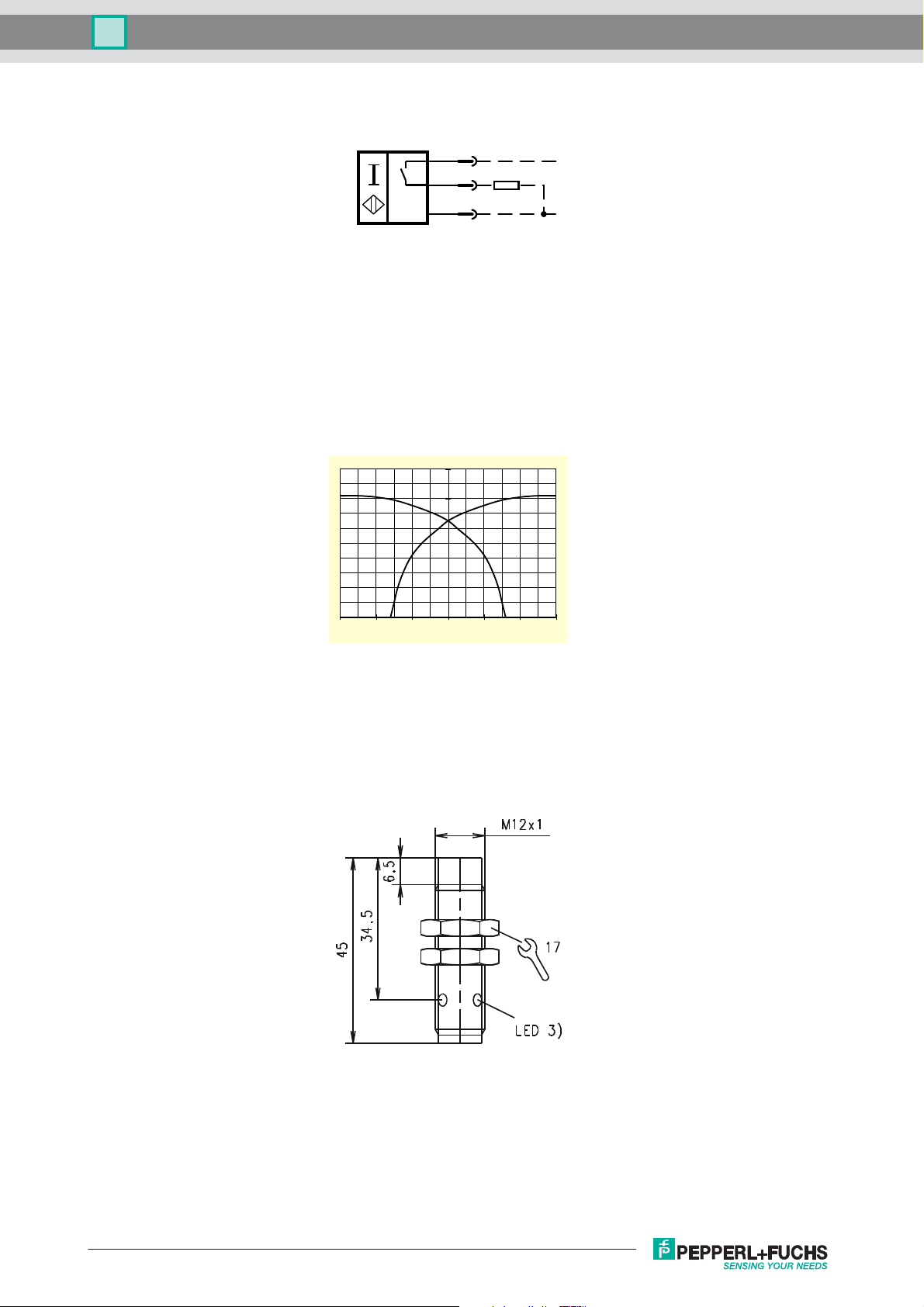
3RG4022-3AG35-PF:
PNP
NO
1
L +
4
3
L -
Response characteristics/Ansprechkennlinie:
y mm
5
4
3
2
1
-6-4-20246
-
0
+
Subject to modifications without notice
Release: 09.09.2010
Copyright Pepperl+Fuchs
 Loading...