

Page 1

ISO9001
MANUAL
Trip Amplifier
2/209
PROCESS AUTOMATION
Page 2

Trip Amplifier 2/209
EN
Table of contents
1 Safety information . . . . . . . . . . . . . . . . . . . . . . . . . . . . . . . . 3
2 Technical data. . . . . . . . . . . . . . . . . . . . . . . . . . . . . . . . . . . . 4
2.1 Features . . . . . . . . . . . . . . . . . . . . . . . . . . . . . . . . . . . . . . . . . . . . . . . . . . . . . . . 4
2.2 Technical data . . . . . . . . . . . . . . . . . . . . . . . . . . . . . . . . . . . . . . . . . . . . . . . . . . 4
2.3 Mounting . . . . . . . . . . . . . . . . . . . . . . . . . . . . . . . . . . . . . . . . . . . . . . . . . . . . . . 6
2.4 Options. . . . . . . . . . . . . . . . . . . . . . . . . . . . . . . . . . . . . . . . . . . . . . . . . . . . . . . . 6
2.5 Safety applications/certificates. . . . . . . . . . . . . . . . . . . . . . . . . . . . . . . . . . . . . 6
2.6 Front view. . . . . . . . . . . . . . . . . . . . . . . . . . . . . . . . . . . . . . . . . . . . . . . . . . . . . . 7
2.7 Dimensions . . . . . . . . . . . . . . . . . . . . . . . . . . . . . . . . . . . . . . . . . . . . . . . . . . . . 7
2.8 Connection. . . . . . . . . . . . . . . . . . . . . . . . . . . . . . . . . . . . . . . . . . . . . . . . . . . . . 8
2.9 Device layout . . . . . . . . . . . . . . . . . . . . . . . . . . . . . . . . . . . . . . . . . . . . . . . . . . . 8
2.10 Block diagram . . . . . . . . . . . . . . . . . . . . . . . . . . . . . . . . . . . . . . . . . . . . . . . . . . 9
2.11 Connection diagram . . . . . . . . . . . . . . . . . . . . . . . . . . . . . . . . . . . . . . . . . . . . . 9
2.12 Front control elements. . . . . . . . . . . . . . . . . . . . . . . . . . . . . . . . . . . . . . . . . . . 10
3 Hardware description . . . . . . . . . . . . . . . . . . . . . . . . . . . . 11
3.1 Mounting instructions . . . . . . . . . . . . . . . . . . . . . . . . . . . . . . . . . . . . . . . . . . . 11
3.2 Cabinet design and heat dissipation . . . . . . . . . . . . . . . . . . . . . . . . . . . . . . . 12
3.3 Connections. . . . . . . . . . . . . . . . . . . . . . . . . . . . . . . . . . . . . . . . . . . . . . . . . . . 12
3.4 Commissioning . . . . . . . . . . . . . . . . . . . . . . . . . . . . . . . . . . . . . . . . . . . . . . . . 13
3.5 Functional test . . . . . . . . . . . . . . . . . . . . . . . . . . . . . . . . . . . . . . . . . . . . . . . . . 14
3.6 Changing current inputs/voltage inputs . . . . . . . . . . . . . . . . . . . . . . . . . . . . . 17
3.7 Maintenance . . . . . . . . . . . . . . . . . . . . . . . . . . . . . . . . . . . . . . . . . . . . . . . . . . 17
3.8 Service instructions . . . . . . . . . . . . . . . . . . . . . . . . . . . . . . . . . . . . . . . . . . . . . 18
4 Software description . . . . . . . . . . . . . . . . . . . . . . . . . . . . . 19
4.1 General. . . . . . . . . . . . . . . . . . . . . . . . . . . . . . . . . . . . . . . . . . . . . . . . . . . . . . . 19
4.2 Numerical parameter list . . . . . . . . . . . . . . . . . . . . . . . . . . . . . . . . . . . . . . . . . 19
4.3 System parameters . . . . . . . . . . . . . . . . . . . . . . . . . . . . . . . . . . . . . . . . . . . . . 30
4.4 Programming example . . . . . . . . . . . . . . . . . . . . . . . . . . . . . . . . . . . . . . . . . . 32
4.5 Error messages . . . . . . . . . . . . . . . . . . . . . . . . . . . . . . . . . . . . . . . . . . . . . . . . 35
4.6 Installation of the PC program . . . . . . . . . . . . . . . . . . . . . . . . . . . . . . . . . . . . 37
DOCT-1946C 2018-07 322903
1
Page 3

Trip Amplifier 2/209
EN
Table of contents
5 Handling without a PC . . . . . . . . . . . . . . . . . . . . . . . . . . . . 39
6 Handling with a PC. . . . . . . . . . . . . . . . . . . . . . . . . . . . . . . 40
6.1 Action 1 – Preparing the hardware . . . . . . . . . . . . . . . . . . . . . . . . . . . . . . . . 40
6.2 Action 2 – Preparing the software . . . . . . . . . . . . . . . . . . . . . . . . . . . . . . . . . 40
6.3 Action 3 – Preparing a back-up copy . . . . . . . . . . . . . . . . . . . . . . . . . . . . . . 40
6.4 Action 4 – How to edit standard programs . . . . . . . . . . . . . . . . . . . . . . . . . . .41
6.5 Action 5 – How to save and send programs. . . . . . . . . . . . . . . . . . . . . . . . . 41
6.6 Action 6 – How to check edited programs . . . . . . . . . . . . . . . . . . . . . . . . . . .42
6.7 Action 7 - How to edit a program. . . . . . . . . . . . . . . . . . . . . . . . . . . . . . . . . . 42
6.8 Action 8 - Ending a job. . . . . . . . . . . . . . . . . . . . . . . . . . . . . . . . . . . . . . . . . . 42
7 Fault finding . . . . . . . . . . . . . . . . . . . . . . . . . . . . . . . . . . . . 43
8 Test programs using the EMULATOR . . . . . . . . . . . . . . . 43
9 Safety concept . . . . . . . . . . . . . . . . . . . . . . . . . . . . . . . . . . 44
9.1 CE marking . . . . . . . . . . . . . . . . . . . . . . . . . . . . . . . . . . . . . . . . . . . . . . . . . . . 45
9.2 Safety related parameters . . . . . . . . . . . . . . . . . . . . . . . . . . . . . . . . . . . . . . . .46
DOCT-1946C 2018-07 322903
2
Page 4

Trip Amplifier 2/209
EN
Attention
Attention
Safety information
1Safety information
Target group: experiences skilled electricians.
The trip amplifier must not be converted or altered in any way.
Device must be mounted outside hazardous areas.
When working on the trip amplifier always comply with national safety and accident
prevention regulations and the safety information contained in this manual. Safety
information is printed in italics like this paragraph and marked accordingly.
Screened cables are recommended for all wiring which leaves the building.
According to IEC 801-5 application class 0 analog inputs must not be subjected to high
energy pulses. In all other respects the unit fulfils IEC 801 to the more stringent
applications class 3.
Redundant analog inputs A and B should be fed from separate sources. The signals
must not differ by more than 5 % since the sister channels are continuously compared
with each other.
In safety applications front push buttons should not be incorporated in those parts of the
program which are relevant to safety. Trip settings should not be changed during
operation. Front push buttons can be locked by placing the jumper KEY in the LOCK
position. The push buttons will then only be used to read values sequentially rather than
alter them (protection against unauthorized changes).
Programs for safety applications should try and avoid conditional branches because this
would simplify the final approval test considerably. This could then be restricted to a
functional test concentrating on the reaction of outputs to input changes.
For safety applications relay outputs must be configured to be normally energized. After
a power down the device will restart automatically. For safety applications it is therefore
necessary to establish suitable external means to resume production in an orderly
fashion.
The serial data link is not a safety related part of the circuitry.
DOCT-1946C 2018-07 322903
3
Page 5

Trip Amplifier 2/209
EN
Technical data
2 Technical data
2.1 Features
• 4-channel isolated barrier
• Input 0/4 mA ... 20 mA
• 4 relay contact outputs
•Programmable
• Simple operation via front buttons
• Lead monitoring
• Galvanic isolation between input, power supply and contact output
• With computational function SIL3
•LCD display
• Self-monitoring
2.2 Technical data
General specifications
Signal type analog input
Supply
Connection z2+, z4-, z6 (PE)
Rated voltage 18 ... 30 V DC, 18 ... 26.4 V AC 48 ... 62 Hz
Power consumption 2 W/2.5 VA
Input
Connection Input A I: d32+, z32-
Input resistance 50 (mA)
Current range 0/4 ... 20 mA (0/1 ... 5 V)
Input A II: d30+, z30Input A III: d28+, z28Input A IV: d26+, z26Input B I: b32+, z32Input B II:b30+, z30Input B III: b28+, z28Input B IV: b26+, z26-
10 k (V)
DOCT-1946C 2018-07 322903
4
Page 6

Trip Amplifier 2/209
EN
Technical data
Output
Connection Output I: z10, d12, d10
Output II: d14, z14, z12
Output III: z16, d18, d16
Output IV: d20, z20, z18
Relay
Switching voltage 50 V
Switching current 2 A AC/DC
Switch power 500 VA/60 W
Mechanical life 50 mio. cycles
Electrical lifetime 0.5 mio. cycles
Response time > 20 ms (variable)
Transfer characteristics
Temperature influence < 0.1 %/10 K
Indicators/settings
Display elements LED 1: trip value 1
LED 2: trip value 2
LED 3: trip value 3
LED 4: trip value 4
LED green: Power on
Configuration via RS 485 interface at the front side
Directive conformity
Electromagnetic compatibility
Directive 2004/108/EC EN 61326-1:2006
Conformity
Protection degree IEC 60529
Ambient conditions
Ambient temperature -10 ... 60 °C (14 ... 140 °F)
Storage temperature -25 ... 80 °C (-13 ... 176 °F)
Relative humidity < 75 % (annual mean)
Mechanical specifications
Protection degree IP20
Mass 300 g
Dimensions 22 x 143 x 193 mm (0.9 x 5.6 x 7.6 in)
Construction type Eurocard 100 x 160 mm (3.9 x 6.3 in) acc. to
< 95 % (30 d/year), no moisture condensation
DIN 41494, front panel 4TE, mountable in 19" rack
DOCT-1946C 2018-07 322903
5
Page 7

Trip Amplifier 2/209
EN
Attention
Attention
Technical data
2.3 Mounting
Devices must be mounted outside hazardous areas.
Fits 19" racks or DIN rail enclosures.
2.4 Options
Additional functions basic functions like mathematics and logical
operations are freely configurable.
Configuration via RS 232 serial data link via commercial PCs or
PC-like units such as SIEMENS PG 685, PG 730,
PG770, PG 790 or MS-DOS PC.
Handling Menu support to SAA standard.
Storage Non volatile EEPROM storage.
Function disable via jumpers.
2.5 Safety applications/certificates
SIL classification SIL3, TÜV Rheinland, 968/EL 292-03/08
acc. to IEC 61508
6
Device must be mounted outside hazardous areas.
DOCT-1946C 2018-07 322903
Page 8
Trip Amplifier 2/209
EN
2/209
ESC
STEP
4
3
2
1
SET
5
P
R
O
G
R
A
M
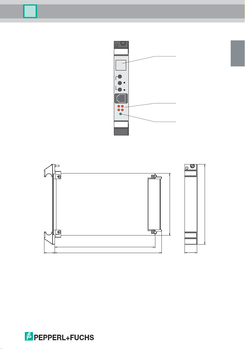
Front view
LED green:
Power supply
LED red:
Limit value
LC display
Technical data
2.6 Front view
2.7 Dimensions
DOCT-1946C 2018-07 322903
17.5 175.5
160
100
143
22
7
Page 9
Trip Amplifier 2/209
EN
2/209
z 10
d 12
d 10
d 26+
z 26-
d 28+
z 28-
d 30+
z 30-
d 32+
z 32-
b 26+
z 26-
b 28+
z 28-
b 30+
z 30-
b 32+
z 32-
z 2+
z 4z 6
24 V
IV
III
II
I
IV
A
B
III
II
I
IV
III
II
I
d 14
z 14
z 12
z 16
d 18
d 16
d 20
z 20
z 18
45312
62718
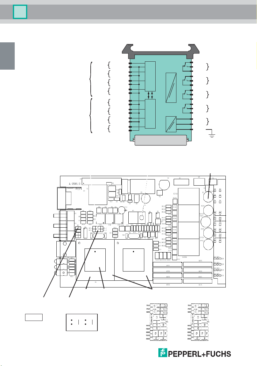
A B
(A) and (B)
input modules with
jumper J
5 V, 10 V,
20 mA
RS 232 C
K1
K2
K3
display
Test X2
X5 - KEY, MODE
jumpers
X2 - TEST
jumpers
line fuse
mP socket space for label processors A + B
push buttons
jumper J
20 mA
5 V
10 V
jumper J
20 mA
5 V
10 V
Technical data
2.8 Connection
2.9 Device layout
8
DOCT-1946C 2018-07 322903
Page 10
Trip Amplifier 2/209
EN
Technical data
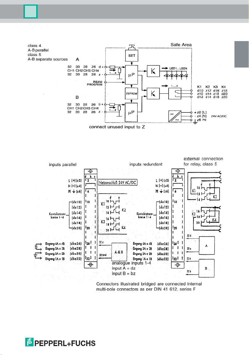
2.10 Block diagram
2.11 Connection diagram
DOCT-1946C 2018-07 322903
9
Page 11
Trip Amplifier 2/209
EN
Technical data
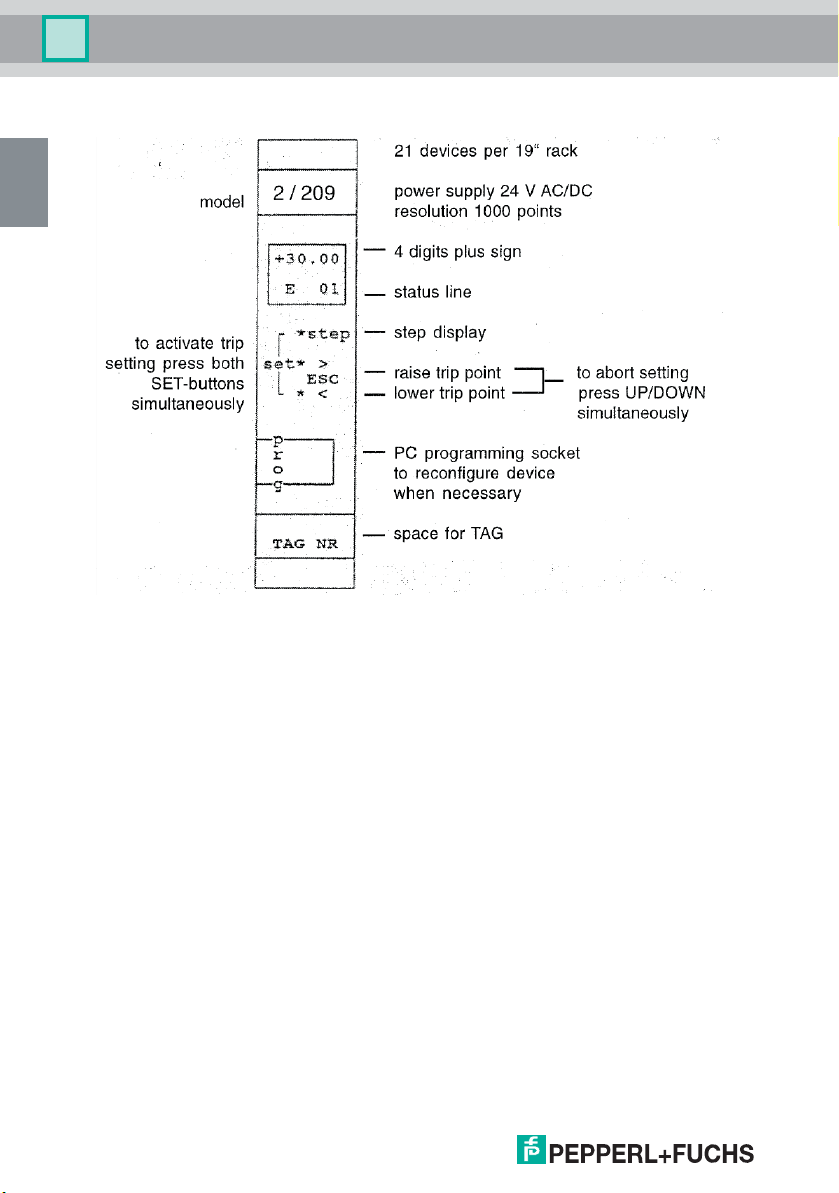
2.12 Front control elements
DOCT-1946C 2018-07 322903
10
Page 12

Trip Amplifier 2/209
EN
Attention
Hardware description
3 Hardware description
3.1 Mounting instructions
Devices must be mounted outside hazardous areas.
The devices are manufactured as narrow plug-in units for 19" racks. The exact
dimensions can be taken from the section "Technical data".
The racks should be mounted in easily accessible positions on walls, in panels, in
cabinets or protective enclosures so that the front panels of the devices take on a vertical
position. The mounting position should be dry and dust-free. Heavy vibrations,
mechanical stress, and strong heat sources are unacceptable. Maximum ambient
conditions must be observed.
The units are EMC-RFI tested to IEC 801.2-5 plus NAMUR AK EMV. Despite their
excellent RFI immunity, the mounting position should not be in the immediate vicinity of
strong electromagnetic fields and be low on RFI. To avoid radio frequency interference
shielded racks and screened cables are recommended. Please observe installation
code of practice. For advice on EMC - RFI see application notes EAN 1610. For best
EMC performance make sure to earth the assigned connector pin.
The units are pushed into the racks fitted with guide rails and female connectors until the
front panels are flush with the front frame of the rack. The units are then connected to the
external wiring via the female connectors. Screw or snap-in fasteners secure the units
against unintentional removal from the rack.
The following mounting recommendations should be observed. A maximum of
21 devices can be fitted in a rack. Power dissipation can be taken form the section
"Technical data". In order to disperse the heat sufficiently the racks should be mounted
in such a way as to ensure best ventilation. The following advice may be useful:
1. It is recommended in particular that permanent overvoltages should be avoided.
2. In particularly adverse operating conditions check the ambient temperature in the
vicinity of the devices (approx. 1 cm away from the front panels). The temperature
should not exceed 60 °C under worst case conditions.
3. Normally natural convection is sufficient for 19" racks in open frames. It has to be
noted however that the topmost rack should not be covered over unless by a cover
plate with sufficient air vents to avoid heat build-up.
DOCT-1946C 2018-07 322903
11
Page 13

Trip Amplifier 2/209
EN
V
Z = –––
G
Z = number of devices per cabinet
V = permissible power dissipation
G = power per device
Attention
Hardware description
3.2 Cabinet design and heat dissipation
Electronic devices will dissipate some of the energy applied to them in the form of heat.
The resulting cabinet temperature must not impair the device function. Therefore the
cabinets should be designed not to exceed the maximum permissible ambient
temperatures as given in the section "Technical data". The following table is based on
an over-temperature of 25 K.
The devices have been designed for 60 °C ambient. Further assuming that the control
room temperature does not exceed 40 °C, the permissible power dissipation in the
cabinet can be given as follows:
1. unforced draught convection 400 W
2. draught convection using vents and filters 800 W
3. draught convection using vents without filters 1600 W
4. unforced natural convection 160 W
5. forced convection ventilators per rack 320 W
6. forced convection using heat exchangers plus forced convection inside and out
1500 W
The number of devices per cabinet can then be computed as follows:
For mixed installations the individual power dissipation of devices can be used to
compute the total power loss to compare with the permissible values.
12
3.3 Connections
For all device types the rules and regulations for the installation of electrical equipment
and wiring (e. g. VDE 0100) of the user country must be observed.
Power and measuring cables have to be kept separate.
Devices are electrically connected using a male and female connector to DIN 41612,
type F. Connections see section "Technical data". The male connector is mounted on
the printed circuit board while the female connector is fitted at the back of the rack.
External connections are normally soldered to the connectors. The solder points are
covered by a heat shrunk sheath e. g. Drakavita Ray Quality H, manufacturer: Deutsche
Schrumpfschlauch Gesellschaft. Other wiring techniques are also acceptable (wirewrap, termipoint, crimp snap-in etc.).
DOCT-1946C 2018-07 322903
Page 14

Trip Amplifier 2/209
EN
4 digits plus sign, status line with one alpha
character plus 2 numerals
nn
T
Hardware description
3.4 Commissioning
The following checks are recommended prior to start-up.
1. Output relay: observe the voltage and current ratings of the relay or electronic
output.
2. Input
– Ensure that the measuring circuit is not subjected to overvoltages.
– Check the input connections and the corresponding jumper setting if the factory
setting is not required.
– For multiple analog inputs check that galvanic isolation is used where
appropriate (e. g. if several signals are also transmitted to another multiple input
device).
3. Power supply: check the supply voltage (see section "Technical data")
Most device settings will be carried out in Software. Check the setting using the
parameter list. This can be addressed via the PC menu
Example
PC menu (details see disk)
Place jumper X5 in position 4–5 for programming.
Connect the device to COM1 or COM2 RS 232 seria l dat a lin ks on your PC. Set your PC
MENU to COM1 or COM2 accordingly via <ALT><C>.
Use the command <ALT><U> to read all data from the device and then printing it
(1 A4 page)
1. LOAD DATA from the device (<ALT><L>).
2. Check constants (<F4> ... <ESC>).
3. Check the program (<F5> ... <ESC>).
Before attempting any changes the old parameters should be stored on disk using
<ALT><W> (see PC HELP TEXT). After effecting the changes these must be stored in
the device using <ALT><S>. Again a back-up copy on disk or WINCHESTER under a
suitable file name is recommended.
After these checks the unit can be plugged into its rack position. Devices are calibrated
ex works. Recalibration is therefore not normally required (see section "Calibration").
A simple functional test can be carried out as for conventional trip amplifiers by
connecting input signal sources to check the relays trip at the setpoint.
DOCT-1946C 2018-07 322903
13
Page 15

Trip Amplifier 2/209
EN
X5
X2
453
12
627
1
8
Hardware description
3.5 Functional test
3.5.1 General
The device will be calibrated ex works following the specifications given with orders. The
unit is operational and approximately 0.2 % accurate as soon as the power is turned on.
It has to be noted however that best performance is only achieved once temperature
balance is reached between the device and its ambient conditions. A device taken from
stock inserted in a warm rack may therefore take 1 ... 2 hours before it reaches its full
accuracy given that the ambient temperature is stable and within the boundaries
mentioned in the section "Technical data".
Factory calibration is carried out at 20 °C ... 25 °C after a 72 hour soak test. Due to the
excellent long term stability of the device no regular maintenance is needed. An annual
check of zero and span is regarded as being sufficient. The PCB carries a row of
jumpers:
Standard setting for row of jumpers X2, X5:
•MODE: X5
–jumper 4–5 PROGRAM
programming mode (program execution stops)
–jumper 3–6 RUN
run mode (device cannot be programmed)
•KEY: X5
– jumper 2–7 KEY LOCK
disable front push button changes
– jumper 1–8 KEY UNLOCK
enable front push button changes
•TEST: X2
–jumper 1–2 TEST
if this jumper is set during the programming mode X5 4–5 testing is enabled.
Device calibration is only possible in this mode of operation.
MODE jumper 4–5 is required for testing. The unit goes offline.
MODE jumper 3–6 for normal operation.
14
DOCT-1946C 2018-07 322903
Page 16

Trip Amplifier 2/209
EN
Hardware description
3.5.2 Testing analog inputs
Analog inputs are tested via the LCD-Display in the front of the device. Download a
program into the device which enables tests of analog inputs (e. g. program TESTE.EDT
in the DEMO directory). The program TESTE.EDT will allow you to display analog inputs
E01 ... E04 in percentage values in the display. Use the push button marked "STEP" to
advance the display to the next input.
The device connections are explained in the data sheet. Inputs A and B have to have the
same input signals applied to them because the program carries out a continuous cross
check between the two for safety reasons.
Use precision signal sources to apply to the inputs. Display readings will be in
engineering units or percentage values depending on the device software.
Use also PC MENUE "TERMINAL EMULATORS". There are the following parameter:
• P711 = input 1
• P712 = input 2
• P713 = input 3
• P714 = input 4
3.5.3 Testing push buttons
Front push buttons are used to set alarm points and to step the display to show
measured values, trip points or computed values. In safety applications changes via
push buttons are sometimes not permitted. Values may then only be read via push
button access.
Download a program into the device which allows several values to be displayed under
push button control (e. g. program TESTE.EDT in the DEMO directory). The program
TESTE.EDT will allow you to display analog inputs E01 ... E04 in percentage values in
the display. Use the push button marked "STEP" to advance the display to the next input.
Setpoints can be altered after placing jumper "KEY" in position 1–8. Press the upper and
lower push buttons "SET" simultaneously. The display will start to flash. Adjust trip points
by using the UP ">" and DOWN "<" push buttons. Store the setting by using the "STEP"
button. Return to normal operation by pressing the two lower push buttons "<" and ">"
simultaneously (ESC). The flashing stops. All three push buttons have now been tested.
Download your operating program and replace the jumpers as shown in
section "Functional test – Generals".
DOCT-1946C 2018-07 322903
15
Page 17

Trip Amplifier 2/209
EN
Hardware description
3.5.4 Testing relay outputs
Relay outputs are used to generate alarms or to identify trip conditions. Download a
program into the device which allows setpoints to be checked by applying input signals
(e. g. program TESTE.EDT in the DEMO directory).
The program offers two lower trips at 20 % and at 40 % plus two high trips at 60 % and
at 80 % with a deadband (hysteresis) of 1 % (pulse stream normally active). A red LED
is assigned to each output to light up on alarm.
After finalizing the output test download your operating program and replace the jumpers
as shown in section "Functional test – Generals".
3.5.5 Testing LEDs
Front LEDs are used to indicate the relay status (red). A green LED can be employed to
indicate the status of the self monitoring feature.
The LEDs can also be used to fulfil other tasks e. g. all LEDs flash: device fault. The
display will then show the error code (see section "Calibration").
LEDs can be tested together with the relays or by placing the MODE jumper in position
4–5 and the TEST jumper X2 to 1–2. The 4 LEDs will then light up in sequence.
3.5.6 Testing the display
The front panel display is used to read measured values, device parameters or trip
settings (top line 4 digits plus sign).
The bottom line offers status indication. An alpha character and 2 digits show which
value is being displayed in the upper line.
Example
T01 = temperature in input 1
L01 = low trip for input 1
The display can be tested together with the push buttons as shown in section "Testing
Push Buttons" or by placing the MODE jumper in position 4–5 and the TEST jumper X2
to 1–2. The display segments will then be turned on.
DOCT-1946C 2018-07 322903
16
Page 18

Trip Amplifier 2/209
EN
Hardware description
3.6 Changing current inputs/voltage inputs
These changes should only be carried out in the laboratory.
Remove and replace jumpers as shown in the following table. Desoldering should only
be carried out using a desoldering wick. Do not use a pump as this may damage the
solder pads. The device does not have to be recalibrated once the changes have been
completed because the components are accurate to within 0.1 %.
In class 4 (DIN V 19250) applications inputs A and B may be driven from the same
source. In this case A and B are to be connected in parallel as shown in figure inputs in
parallel in section "Layout". Open all the jumpers on module B and connect the positive
end of the sister channels together.
Input 0/4 mA ... 20 mA
1 A101 A501 A101 A501 A101 A501
2 A201 A601 A201 A601 A201 A601
3 A301 A701 A301 A701 A301 A701
4 A401 A801 A401 A801 A401 A801
channel/module A B A B A B
jumper X9
0/1 V ... 5 V
jumper X10
For jumper locations see device layout in section "Layout".
3.7 Maintenance
The devices do not employ mechanical components which are exposed to wear and tear
other than the front push buttons and relays. The circuits are well selected only
incorporating high quality parts.
Therefore no regular maintenance is required as long as the maximum operating
conditions are observed. Due to the excellent long-term stability calibration of zero and
span need only be checked once a year. The relay life is given in technical data in
section "Technical data".
0/2 V ... 10 V
jumper X11
DOCT-1946C 2018-07 322903
17
Page 19

Trip Amplifier 2/209
EN
Hardware description
3.8 Service instructions
In case of dubious measuring results please check all external connections carefully. It
is also good practice to check that the desired program has actually been stored in
EPROM. A TAG number can be stored for identification purposes (also see
section "Commissioning"). If there is no doubt about the fault lying with the device, it is
seldom possible to repair the unit on site. Local analysis should be restricted to a check
of the fuses.
Each fuse is tagged with its nominal value. Fuses must always be replaced by their
equivalents. Fuse positions may be taken from section "Technical data" figure device
layout.
Fuse Value Function
F1 0.630 A Power supply
F101 3.15 A Relay 1
F201 3.15 A Relay 2
F301 3.15 A Relay 3
F401 3.15 A Relay 4
Other faults require laboratory tests. Circuit diagrams can be made available at request.
Repairs can be carried out by our service department quickly and efficiently if units are
returned to the factory. Spares help to maintain production in such cases.
DOCT-1946C 2018-07 322903
18
Page 20

Trip Amplifier 2/209
EN
Attention
Software description
4Software description
4.1 General
The device is freely programmable like a PLC.
Make sure to use the dedicated 2/209 - PC connector cable.
The following sections explain the software features of the unit. They are of interest
mainly to those users who intend to write their own software. For standard applications
skip reading sections "Programm and commands" to "System parameters".
Devices can be programmed using a personal computer. A MENU supported software
package is available for PC users (see PC MENU disk).
Programming or reconfiguring is not required for standard applications. Therefore the
following sections will mainly be used for writing new software.
In the normal way trip settings are accomplished via front panel push buttons. Additional
options are explained in the following sections. A personal computer will allow for
maximum user friendliness since all device functions are MENU supported via context
sensitive HELPs.
numerical range:
+ /-1.18E-38 ... +/-3.39E+38
accuracy:
7 decimals
The trip amplifier is designed around a 16 Bit microprocessor.
Hardware and Software have been developed to safety standards (see section
"Safety concept").
4.2 Numerical parameter list
All device parameters are listed in numerical order.
4.2.1 Program and commands P100 ... P299
Program changes can only be undertaken with jumper <MODE> in the <ENABLE>
position.
Trips are only monitored with jumper MODE disabled (RUN).
Parameters P100 to P299 contain up to 200 programming steps. User programs can be
entered to adapt the device to various applications. A powerful EDITOR is available for
PC users. Once edited using (F2) programs must be compiled using compiler (F3).
Available commands and operands can be taken from the following list.
DOCT-1946C 2018-07 322903
19
Page 21

Trip Amplifier 2/209
EN
Software description
4.2.2 Operands
AE1 ... AE4 analog inputs 1 ... 4 return up-to-date values (0 ... 1) of analog inputs (read only)
DE1 ... DE4 digital inputs 1 ... 4 derived from analog inputs
TE1 ... TE3
TR2 ... TR3
X01 ... X20 variables 1 .. 20 read and write
K01 ... K20 constants 1 .. 20 stored in EEPROM (read only)
Fixed values (program) and corresponding figures
Z00 Z01 Z02 Z03 Z04 Z05 Z10 ZM1 Z1H Z1T
0 1 2 3 4 5 10 -1 100 1000
CRP
CRC
4.2.3 Mathematical operations
Command Call Formula
Add ADD,op1,op2,op3 op3 = op1 + op2
Subtract SUB,op1,op2,op3 op3 = op1 - op2
Multiply MUL,op1,op2,op3 op3 = op1 x op2
Divide DIV,op1,op2,op3 op3 = op1/op2
Square root SQR,op1,op2 op2 = SQR(op1)
Absolute ABS,op1,op2 op2 = ABS(op1)
Logarithm (nat. LOG) LOG,op1,op2 op2 = LOG(op1)
Exponential function EXP,op1,op2 op2 = e^op1
Sine SIN,op1,op2 op2 = SIN(op1)
Cosine COS,op1,op2 op2 = COS(op1)
Tangent TAN,op1,op2 op2 = TAN(op1)
Arc-tangent ATN,op1,op2 op2 = ATN(op1)
Move MOV,op1,op2 op2 = op1
Clear CLR,op1 op1 = -1
Clear all var. CLA X01 ... X20 = -1
Logical AND AND,op1,op2,op3 op3 = op1 and op2
Logical OR ORA,op1,op2,op3 op3 = op1 and op2
DEx = -1 when AEx < 33 %
DEx = 0 when AEx >= 33 % and <= 66 %
DEx = 1 when lAEx > 66 %
(read only)
push button inputs (1 when pressed)
push button inputs (0 when pressed)
checksum of the user program
checksum of user constants and calibration
op3 = 1 when op1 and op2 = 1
op3 = -1 when op1 or op2 = -1
op3 = 1 when op1 or op2 = 1
op3 = -1 when op1 and op2 = -1
DOCT-1946C 2018-07 322903
20
Page 22

Trip Amplifier 2/209
EN
Software description
4.2.4 Conditional branches
Branch on equal
Call: IEQ,op1,op2,op3
Formula: if op1 = op2 branch to op3
Branch on not equal
Call: INE,op1,op2,op3
Formula: if op1 <> op2 branch to op3
Branch on greater or equal
Call: IGE,op1,op2,op3
Formula: if op1 >= op2 branch to op3
Branch on lower
Call: ILO,op1,op2,op3
Formula: if op1 < op2 branch to op3
Unconditional branch
Call: GTO,op1
Formula: branch to op3
4.2.5 Timers and other operations
Command Call Formula
End of program END end of program
No operation NOP no operation
Timer TIM,op1 read timer and delete (time in ms)
Timer TIN,op1 read timer (time in ms)
Wait WAI,op1 wait so many ms (max. 10,000 ms)
Filter analog in FIL,op1 number of averaged input values
Watchdog WDT,op1 starts the watchdog (max 10,000 ms)
(max. 100) program waits for
execution
4.2.6 Output operations
Command Call Formula
De-energize relay RD1...RD4, op1 relay de-energized within limits
Energize relay RE1...RE4,op1 relay energized within limits
Set LEDs SL1...SL5,op1 set LEDs
Set LEDs reverse logic RL1...RL5,op1 set LEDs
LED flash FL5,op1 flashing LED 5 (green)
The following commands must be placed at the beginning of a program
On delay ND1...ND4, op1 ON-Delay
Off delay FD1...FD4, op1 OFF-Delay
DOCT-1946C 2018-07 322903
op1 = -1 relay off
op1 = 0 previous status
op1 = 1 relay energized
op1 = -1 relay off
op1 = 0 previous status
op1 = 1 relay energized
op1 = -1 off
op1 = 0 previous status
op1 = 1 on
op1 = 1 off
op1 = 0 previous status
op1 = -1 on
op1 = -1 off
op1 = 0 previous status
op1 = 1 on
op1 = delay (max 10,000ms)
op1 = delay (max 10,000ms)
21
Page 23

Trip Amplifier 2/209
EN
Software description
4.2.7 Special Operations
Display menu:
The DSP command has to be placed at the beginning of a program. DISPLAY
commands must be in sequence. Other commands follow.
The order in which display commands are used determines the sequence of parameters
displayed when pushing the STEP key on the device front.
Example
• input 1, trip point 1,
input 2, trip point 2
or
• input 1, input 2,
trip point 1, trip point 2
Front push buttons will operate ONLINE, i. e. trip points continue to be monitored while
the buttons are pushed. The program will read the push buttons once every cycle. It may
therefore be necessary to press a push buttons several times before the unit responds.
Push buttons can be used to chang e co nstan ts. Th is i s used to set trip points. Press SET
to initiate changes (two keys simultaneously to protect against unintentional changes).
The STATUS line will flash.
Use UP/DOWN ">" "<" push buttons to adjust the value.
Store the result in non-volatile EEPROM by pressing STEP key. Prior to storing the value
in EEPROM you can restore the previous setting by pressing the UP/DOWN buttons
simultaneously "ESC". The keys terminate the programming mode (display stops
flashing). If keys are not pressed for 30 seconds the SET mode is terminated
automatically.
Action:
Display operand op1 in mode op2.
The lower line will carry the alpha character a and the numerals nn. DSP commands
have to be placed at the beginning of a program. The front push buttons are used to step
DSP commands or change constants.
Call DSP,op1,op2,op3,op4
In the EDITOR operands op3 ... op5 are grouped together.
Example
DSP,X01,Z00,E01 (see example programs in DEMO directory)
DSP = display
op1 = variable or constant upper line
op2 = mode: (0 = float, 1 ... 4 = (no - 1)decimals)
op3 = ASCII: (A ... Z e. g. "#E")
op4 = num. (0 ... 9 e. g. "#1") lower line
op5 = num. (0 ... 9 e. g. "#0")
DOCT-1946C 2018-07 322903
22
Page 24

Trip Amplifier 2/209
EN
Software description
4.2.8 Live zero conversion
Call CLI, op1, op2, op3, op4 (convert live input)
Formula op4 = (op1-0.2) / 0.8 x (op3-op2) + op2
This command serves to convert live zero input signals into engineering units. That way
measured values and trip points can be displayed as °C, m
units. The user does not have to establish conversion formula for himself.
Example
• Begin = 180 at 4 mA
• Full scale = 380 at 20 mA
• Display = 280 at 12 mA
The device front offers space for entering TAG numbers and engineering units. Enter
•0 = beginning
• 100 = full scale
in order to display percentage values.
Live zero signals: 4 mA ... 20 mA, 1 V ... 5 V, 2 V ... 10 V
4.2.9 Dead zero conversion
Convert dead zero input signals into engineering units.
Call CDI, op1, op2, op3, op4 (convert dead input)
Formula op4 = op1 x (op3-op2) + op2
The function is equivalent to the live zero conversion.
Dead zero signals: 0 mA ... 20 mA, 0 V ... 5V, 0 V ... 10 V
CLI = live zero - measuring range
op1 = input (AE1 ... AE4)
op2 = beginning of range
op3 = full scale
op4 = result
CDI = dead zero - measuring range
op1 = input (AE1 ... AE4)
op2 = beginning of range
op3 = full scale
op4 = result
3
/h, % or other engineering
DOCT-1946C 2018-07 322903
23
Page 25

Trip Amplifier 2/209
EN
Software description
4.2.10 Trip high on mid – hysteresis
This command is used to monitor a high alarm. You can monitor inputs or computed
values.
Call AHM,op1,op2, op3, op4 (alarm high mid hysteresis)
Formula op4 = 1 for alarms or if op4 was 1 before
Example
ADD, AE1, AE2, op1
Monitors the average of input 1 and input 2 etc.
Use Operand op4 to energize or de-energize relays.
Trip points are in engineering units as determined by the beginning and end of range (full
scale) values. This relieves the user from tedious conversion tasks. This command sets
the trip point in the centre of the deadband (hysteresis op3 as with conventional trip
amplifiers).
Example
• high contact = 60 %
• hysteresis = 6 %
• alarm > 63 %
• no alarm < 57 %
The hysteresis is also set in engineering units (0.1 % to 100 %).
AHM = alarm high contact on centre hysteresis
op1 = value to be monitored (e. g. AE1 ... AE4)
op2 = trip point
op3 = hysteresis
op4 = result
op4 = 0 while inside deadband or if op4 was 0 before
op4 = -1 when there is no alarm
4.2.11 Trip low on mid – hysteresis
This command is used to monitor a low alarm. You can monitor inputs or computed
values.
Call ALM,op1,op2, op3, op4 (alarm low mid hysteresis)
Formula op4 = 1 for alarms or if op4 was 1 before
ALM = alarm low contact on centre hysteresis
op1 = value to be monitored (e. g. AE1 ... AE4)
op2 = trip point
op3 = hysteresis
op4 = result
op4 = 0 while inside deadband or if op4 was 0 before
op4 = -1 when there is no alarm
Example
• high contact = 60 %
• hysteresis = 6 %
• alarm > 57 %
• no alarm < 63 %
24
DOCT-1946C 2018-07 322903
Page 26

Trip Amplifier 2/209
EN
Software description
4.2.12 Trip high on set-point
This command is used to monitor a low alarm. You can monitor inputs or computed
values. In contrast to previous alarms this one triggers exactly on the preset trip point.
The hysteresis or deadband will then be to one side of the set-point.
Call AHS,op1,op2,op3,op4 (alarm high on set-point)
Formula op4 = 1 for alarms or if op4 was 1 before
Example
• high contact = 60 %
• hysteresis = 3 %
• alarm > 60 %
• no alarm < 57 %
The hysteresis is also set in engineering units (0.1 % to 100 %).
4.2.13 Trip low on set-point
This command is used to monitor a low alarm. You can monitor inputs or computed
values.
Call ALS,op1,op2,op3,op4 (alarm low on set-point)
Formula op4 = 1 for alarms or if op4 was 1 before
Example
• high contact = 60 %
• hysteresis = 3 %
• alarm < 60 %
• no alarm > 63 %
The hysteresis is also set in engineering units (0.1 % to 100 %).
AHS = alarm high contact exactly on set-point
op1 = value to be monitored (e. g. AE1 ... AE4)
op2 = trip point
op3 = hysteresis
op4 = result
op4 = 0 while inside deadband or if op4 was 0 before
op4 = -1 when there is no alarm
ALS = alarm low contact exactly on set-point
op1 = value to be monitored (e. g. AE1 ... AE4)
op2 = trip point
op3 = hysteresis
op4 = result
op4 = 0 while inside deadband or if op4 was 0 before
op4 = -1when there is no alarm
DOCT-1946C 2018-07 322903
25
Page 27

Trip Amplifier 2/209
EN
Software description
4.2.14 Trip 2 of 3 selector
Call SEL,op1,op2,op3,op4,op5,op6,op7,op8,op9
Formula op5 and op6 show:
SEL = select the deviating channel
op1 = input 1
op2 = input 2
op3 = input 3
op4 = tolerance band
op5 = tolerance band hysteresis
op6 = signal alarm -1, 0, 1 (channels are deviates)
op7 = channel alarm -1, 0, 1(channels are different)
op8 = average of acceptable inputs
op9 = faulty channel (0, 1, 2, 3, 123)
op4= 1 for alarms or if op. was 1 before
op4 = 0 while inside deadband or if op. was 0 before
op4 = -1 when there is no alarm
Example
SEL,E01,E02,E03,K01,K02,X01,X02,X03,X04
Normal operation
• signal alarm = -1
• channel alarm = -1
• average = (E1 + E2 + E3) / 3
• faulty channel = 0
Single fault
• signal alarm = 1
• channel alarm = -1
• average = (Ex + Ey) / 2
• faulty channel = E1 or E2 or E3
Multiple fault
• signal alarm = 1
• channel alarm = 1
• average = previous value
• faulty channel = 123
Three input signals op1, op2, op3 are monitored for equality. If one input leaves the
tolerance band op4 around the average of the signals, the signal alarm op6 will be
activated. If all inputs are different, the channel alarm op7 will be activated.
The faulty channel can be read in op9. Use the DISPLAY command to read the value in
the display in the front panel. The average op8 of those values which are within the
tolerance band can also be displayed. Variables op6, op7, op8, op9 must not be
overwritten during the remaining user program.
DOCT-1946C 2018-07 322903
26
Page 28

Trip Amplifier 2/209
EN
Software description
4.2.15 Trip rate of change alarm
Prior to calling this rate of change alarm use the timer command TIM,op5 to enter the
time since the last call in memory cell op5.
An input or a computed value op1 is monitored for change op3 per time interval op2. The
up-to-date value of op1 will be compared with the old value in op6 (op3 = op1 - op6)
when the time integral op7 > op2. If the change per time interval op3 is above 0 the
gradient is positive. If the change per time interval op3 is less 0 the gradient is negative.
Memory cells op6 to op9 must not be overwritten during the remaining user program.
Call GRD,op1,op2,op3,op4,op5,op6,op7,op8,op9
Formula op9 = 1 for alarms or if op9 was 1 before
Example
GRD,E01,K01,K02,K03,X01,X02,X03,X04,X05
GRD = (gradient) monitor rate of change
op1 = input value to be monitored
op2 = time interval in ms
op3 = max change per time interval
op4 = hysteresis
op5 = time since last call
op6 = input memory (start value)
op7 = time memory (integral of op5 in ms)
op8 = alarm memory
op9 = alarm -1, 0, 1
op9 = 0 while inside deadband or if op9 was 0 before
op9 = -1 when there is no alarm
DOCT-1946C 2018-07 322903
27
Page 29

Trip Amplifier 2/209
EN
Software description
4.2.16 Trip stuck sensor alarm
Prior to calling this rate of change alarm use the timer command TIM,op5 to enter the
time since the last call in memory cell op5.
An input signal or a computed value op1 is monitored to see if the value has changed by
more than the required minimum value op3 during the sample time (time interval op2). If
the minimum change has not been achieved, an alarm is generated because it must now
be assumed that there is a fault in the circuit which is under observation.
Memory cells op6 to op9 must not be overwritten during the remaining user program.
Call STS,op1,op2,op3,op4,op5,op6,op7,op8,op9,op10
Formula op10 = 1 for alarms or if op10 was 1 before
Example
STS,E01,K01,K02,K03,X01,X02,X03,X04,X05,X06
STS = stuck sensor
op1 = input
op2 = time interval in ms
op3 = min change per time interval
op4 = hysteresis
op5 = time since last call in ms
op6 = min input memory
op7 = max input memory
op8 = time memory (integral of op5)
op9 = alarm memory
op10 = alarm -1,0,1
op10 = 0 while inside deadband or if op10 was 0 before
op10 = -1 when there is no alarm
DOCT-1946C 2018-07 322903
28
Page 30

Trip Amplifier 2/209
EN
Software description
4.2.17 Trip Analog Monitor (setpoint and line monitor)
An input signal op2 (op1 = live or dead zero) in converted into engineering units using
op3 = beginning o.r. and op4 = full scale.
The result is stored in op12. The signal will then be monitored for line interrupts and
overrange (Fault) plus a setpoint (op5) depending on op6 = low limit or high limit.
Call ANA,op1,op2,op3,op4,op5,op6,op7,op8,op9,op10,op11,op12
Formula op10 = 1 for alarms or if op10 was 1 before
Example
ANA,Z01,AE1,K01,K02,K03,Z00,X01,K04,X03,X04,X05,X06
Comment
op1 = input mode 0 = dead zero (21 mA)
ANA = analog input monitor
op1 = input mode
op2 = input
op3 = beginning of range
op4 = full scale
op5 = trip point
op6 = trip mode (0=low limit; 1=high limit)
op7 = Reset (> 0 then reset)
op8 = delay (delay = op8 x program cycle)
op9 = delay counter
op10 = alarm memory
op11 = line interrupt/overrange (fault)
op12 = analog output
op10 = -1 while inside deadband
op11 = 1 for fault or if op11 was 1 before
op11 = -1 while inside deadband
Line monitor trips at
1 = live zero (3.6 mA and 21 mA)
2 = live zero (0.5 mA and 21.5 mA)
The reset variable op7 is used to clear alarm or fault conditions. This allows you to HOLD
the Alarm and RESET it via a variable value (op7) under software control. The variable
may be governed by an analog input or the front push buttons.
The alarm will be delayed by op8. The delay will reach 1 second, if op8 = 25 and the
average program execution time is estimated to be 40 ms.
If an alarm or fault are detected this information will be stored. If both fault and alarm are
detected, fault will be predominant.
Memory cells op9 to op11 may only be read during the remaining program. They must
not be overwritten.
DOCT-1946C 2018-07 322903
29
Page 31

Trip Amplifier 2/209
EN
Software description
4.3 System parameters
System parameters help to analyse problems and locate faults.
4.3.1 Software version P700 (read only)
This parameter gives access to the number of the current software version.
Example
2/209 V 1.18
4.3.2 Device ID P701 (read and write)
This parameter contains a device identification or TAG No. of up to 12 characters. It
does not have any influence on program execution. It can be employed to advantage
when storing data of several devices on a personal computer.
Example
2/209
4.3.3 Jumper KEY P704
Displays the status of the jumper KEY.
Example
Enter: P704 <Enter>
Display: P704 = 1 (1 = KEY ENABLE)
1 = push button changes unlocked
0 = push button changes locked
4.3.4 Jumper MODE P705
Displays the status of the jumper MODE.
Example
Enter: P705 <Enter>
Display: P705 = 0 (0 = MODE DISABLE)
0 = programming disabled
1 = programming enabled. Trips are NOT monitored
4.3.5 Jumper TEST P706
Displays the status of the TEST jumper.
Example
Enter: P706 <Enter>
Display: P706 = 0 (0 = TEST DISABLE)
1 = TEST Mode (calibration enabled)
0 = normal mode (calibration disabled)
DOCT-1946C 2018-07 322903
30
Page 32

Trip Amplifier 2/209
EN
Software description
4.3.6 Device Programming P707 (PC menu only)
Entering parameter P707 = 1 will delete all data in EEPROM. The device will then expect
to receive a new identification ID, 20 constants, 200 programming steps and a CRC
(checksum) following data transmission.
Once data transmission has been completed successfully data are copied to EEPROM
followed by an echo of 0. Otherwise 1 is echoed. The PC program will control data
transmission and the generation of the CRC.
4.3.7 Test parameters
Test parameters are used for electrical device checks.
Check analog inputs and push buttons (ONLINE)
P711 analog input 1 corresponding to 0 ... 1 (read)
P712 analog input 2 corresponding to 0 ... 1 (read)
P713 analog input 3 corresponding to 0 ... 1 (read)
P714 analog input 4 corresponding to 0 ... 1 (read)
Check calibration data (ONLINE). Both microprocessors contain calibration data about
the redundant analog inputs assigned to them.
CPU A
P781 read calibrate analog input 1A
P782 read calibrate analog input 2A
P783 read calibrate analog input 3A
P784 read calibrate analog input 4A
P785 read calibrate analog input 1B
P786 read calibrate analog input 2B
P787 read calibrate analog input 3B
P788 read calibrate analog input 4B
CPU B
4.3.8 Calibration
Devices are calibrated ex works. Therefore recalibration is not normally required after
commissioning. An annual check is regarded as being sufficient. Range changes or live/
dead zero changes do not involve recalibration.
Recalibration is also not required after changing from current to voltage inputs or vice
versa (also 5V ... 10V) because precision resistors have been used.
Set the MODE jumper to PROG (4–5) and the TEST jumper to X2. Connect the device
to the PC using the TERMINAL EMULATOR <ALT><E> (see section "Numerical
parameter list").
1. Set all analog inputs to 100 %
2. Enter P790=1 (calibrate analog inputs)
3. Display P790 = n n = 0 o.k.
n = 1...8 error in channel n
n = 9 jumper TEST disabled
DOCT-1946C 2018-07 322903
31
Page 33

Trip Amplifier 2/209
EN
Software description
After calibration has been completed the jumpers have to be changed back to the
operating mode. MODE = RUN (X5 3–6) and TEST jumper removed.
The calibration procedure eliminates tolerances of the precision resistors in the input
channels of the device. Conventional potentiometers have been replaced by nonvolatile EEPROM memory.
4.3.9 Constants
P801 ... P820 contain constants K01 ... K20.
Constants are stored in EEPROM and can be altered ONLINE using the front push
buttons (see special commands). External access is often not permitted in safety
applications.
Data will be retained upon loss of power.
4.3.10 Variables
P901 ... P920 contain variables X01 ... X20.
Variables are stored in RAM and will be used for computed or interim values.
RAM contents will be lost upon loss of power.
4.4 Programming example
Install your PC software for the 2/209 trip amplifier (see section "How to install your
program").
Power the trip amplifier (24 V DC) and connect it to the personal computer (COM1 or
COM2). Analog inputs should be connected to signal sources.
Set the MODE jumper (X5) to programming X5.4 - X5.5 (see section "Functions –
General").
Start the PC program by entering START/1 (device connected at COM1 of the PC) or
enter START/2 (device connected at COM2). The screen will now show the main
MENU.
Open communication by entering keys <ALT><E> simultaneously. The selected serial
data link COM1 or COM2 should be echoed in the display window. Now enter the
command P700 followed by RETURN (ENTER).
The communication window will display as follows:
P700
P700=2/209-V3.0 (device version)
In case there is no reply from the device, please check your connection:
a) use the correct cable
b) use the correct serial data link COM1 or COM2
c) check the jumper positions
of the device (see above).
DOCT-1946C 2018-07 322903
32
Page 34

Trip Amplifier 2/209
EN
Software description
Once communication has been established between the PC and the device close the
communication window using <ESC>.
Now activate the EDITOR using key <F2>. Press RETURN <ENTER>, to enter the
selection box.
Move to the DEMO directory using arrow keys and acknowledging with <ENTER>.
Select the file TEST_E.EDT and acknowledge with RETURN. The test program will now
be displayed.
Colons are used to introduce comments. You can step through the program using the
arrow keys. A program always consists of constants K01 ... K20 and statements.
The software example is used to monitor 4 inputs.
E01 low limit
20 % normally energized
1% hysteresis
LED 1 On for alarm
E02 low limit
40 % normally energized
1% hysteresis
LED 2 On for alarm
E03 high limit
60 % normally energized
1% hysteresis
LED 3 On for alarm
E04 high limit
80 % normally energized
1% hysteresis
LED 4 On for alarm
The WDT,K08 statement starts a watchdog which will halt the system after 1,000 ms
should the program fail to pass this statement.
The following values can be addressed on the front LCD display:
E01 analog input 1 in %
E02 analog input 2 in %
E03 analog input 3 in %
E04 analog input 4 in %
L01 low limit for E01 in %
L02 low limit for E02 in %
H01 high limit for E03 in %
H02 high limit for E04 in %
C00 checksum of device (program, constants, calibration)
P00 checksum of the program
T00 program execution time in ms.
DOCT-1946C 2018-07 322903
33
Page 35

Trip Amplifier 2/209
EN
Software description
Leave the EDITOR using ESC. At the top of the screen the question "SAVE Y/N" will
appear. Reply "N" unless you want save changes.
If you have made changes in the source code and you want to safe it, please reply
with "Y".
The program now has to pass the COMPILER to become executable. Activate the
COMPILER using key <F3>. Any program which has just passed the EDITOR will
automatically be addressed by the COMPILER. Acknowledge using RETURN. The
screen will show "data loaded from compiler". Acknowledge using ESC.
Send the translated program to the trip amplifier using <ALT><S> (press <ALT> and
<S> simultaneously). Acknowledge the question "are you sure" with RETURN. A new
windo w will appear on the screen and you will be able to watch data being transferred to
the trip amplifier. After about 2 minutes data transfer will be completed and a checksum
is formed to be stored as an unmistakable value in EEPROM (P00).
Set jumper MODE to RUN X5.3 - X5.6 (see section "Functions – General"). The trip
amplifier will now perform the desired function.
DOCT-1946C 2018-07 322903
34
Page 36

Trip Amplifier 2/209
EN
100
F54
Software description
4.5 Error messages
When an error is detected while a program is being executed, the processor will halt and
all LEDs will flash. Relay outputs will be de-energized. The error code will be shown on
the display.
Example
Error 54 in line 100 will lead to the following display.
PC screen: F54 in 100
Display:
Fault Meaning Action
11 analog input 1 difference in CPU A and B Check input signals.
12 analog input 2 difference in CPU A and B
13 analog input 3 difference in CPU A and B
14 analog input 4 difference in CPU A and B
15 difference in the program monitor of CPU A and B
20 wrong length of start bits for communication
21 time-out in the parallel CPU (no data from parallel CPU)
22 time-out on main program (user programs are interrupted)
23 unused interrupt
24 time-out through watchdog WDT command Check program execution time.
39 program runtime error in the operating system
38 program runtime error in the user program
40 CRC error in RAM (retransmit program and constants) Briefly switch off power to generate
41 ERROR unable to switch off relay output 1 Briefly switch off power to generate
42 ERROR unable to switch off relay output 2
43 ERROR unable to switch off relay output 3
44 ERROR unable to switch off relay output 4
45 power monitor (internal 5V-supply < 4.5V or > 5.5V)
46 CPU not functioning properly
49 AD converter, MUX, reference input faulty
51 RAM fault Inverter and cross talk check failed.
52 CRC error in EPROM Briefly switch off power to generate
53 faulty statement e. g. ADD,Z00,Z01,Z00
The result of an operation cannot be stored in a fixed value (Z00).
54 faulty statement e. g. ADD,X01,X02,X03,X04,...
The ADD statement should only be followed by 3 operands.
These are to be followed by the next statement (X04 is wrong).
55 program counter less than 100 or greater 299 Check your program and its
a RESET.
a RESET. Repair if necessary.
a RESET.
statements.
DOCT-1946C 2018-07 322903
35
Page 37

Trip Amplifier 2/209
EN
Software description
Errors lead to a program interrupt. All the LEDs will be turned on and the output relays
are de-energized.
• Error Axx: the error has been recognized by CPU A.
• Error Bxx: the error has been recognized by CPU B.
As a first action briefly switch off the power supply to the device. The card will be RESET
and all functions will be tested.
You may be able to correct faults in the execution of a program by setting the MODE
jumper to PROG and then back again to RUN. If necessary reload the program from the
PC.
Should the device indicate an error during programming due to strong electromagnetic
bursts briefly switch off power before resuming your task.
DOCT-1946C 2018-07 322903
36
Page 38

Trip Amplifier 2/209
EN
Software description
4.6 Installation of the PC program
The 2/209 software will operate on any IBM compatible PC with 512 kB memory and an
MS-DOS or PC-DOS operating system Version 3.0 or higher.
For maximum user friendliness install a Mouse and an EGA or VGA monitor. However,
the program will also run without a Mouse and with a monochrome monitor. If you want
to use a Mouse, make sure the corresponding driver is loaded. It is best to incorporate
the driver in the start batch using an editor to do so (file: START.BAT).
If a WINCHESTER drive is available, a new directory should be generated. Afterwards
all the files should be copied from the floppy disk to the new directory.
Example
•c:
• md PC2209
• cd PC2209
• xcopy a:*.* /s
•dir
Now the following files should be listed:
START BAT Start batch
MAIN_209 EXE Menu support
COMP_209 EXE Compiler
SIMU_209 EXE Emulator
EDIT_209 EXE Editor
SYNATAX OPL Syntax for the compiler
TXT_209G TXT German menu
TXT_209E TXT English menu
HLP_209G HLP German help
HLP_209E HLP English help
EDT_209G HLP German help for editor functions
EDT_209E HLP English help for editor functions
DEMO DIR Subdirectory with sample programs
STD DIR Subdirectory with standard programs
While in DOS type TYPE START.BAT to display the START file.
REM MOUSE here you may want to add the MOUSE driver; in
that case please remove the REM statement.
MAIN_209 %1 %2 this program starts the menu support.
Activate the english version by entering START /e /2. The menu will then appear on the
screen.
DOCT-1946C 2018-07 322903
37
Page 39

Trip Amplifier 2/209
EN
Software description
The following START-up parameters are possible:
/g German help *
/e English help
/0 DEMO mode active *
/1 Serial link via COM1
/2 Serial link via COM2
Start options marked by a star * will be assumed unless other parameters are used.
Connect the trip amplifier via a serial data link (RS 232) to the personal computer. The
desired PC port "COM" is assigned during start-up (/2 = COM2) as shown above. The
port may be changed under MENU support using (<ALT><C>). Only lines GND (7), TXD
(2) and RXD (3) of the PC need to be connected with the trip amplifier. A suitable cable
is available as an accessory.
Menu items are explained via HELP text. Use key F1 for HELP. Context sensitive HELP
texts simplify matters when working with the program. Every line of the menu can thus
be explained in detail. HELP is also accessible using alphabetical search.
DOCT-1946C 2018-07 322903
38
Page 40

Trip Amplifier 2/209
EN
Handling without a PC
5 Handling without a PC
In the normal way front panel push buttons can be used to adjust set points read on the
digital display. Set points are secured against unintentional adjustments (jumper X5 2–
7). Enable push button adjustments by setting jumper X5 to 1–8.
In order to activate the UP/DOWN push buttons both SET buttons must be pressed
simultaneously. The display will start to flash. Set points can now be raised using > or
lowered using < push buttons. Keep the push button down to accelerate.
Use the STEP button to save the new setting. The new value will not be accepted until
STEP is pressed and the next value is displayed. If you want to restore the previous
setting and erase the new one you can do so by pressing both > and < simultaneously
(ESC) prior to pressing the STEP button.
The status line indicated which value is being displayed at present e. g.
• E01 = input 1
• T01 = temp. 1
• F01 = flow 1
• L01 = low alarm 1,
• H01 = high alarm 1
Front push buttons can be disabled via an internal jumper (see section "Functional test
– Generals").
In that case measured values and trip setting can be displayed online, but alterations will
not be possible. The basic device function is outlined on the TAG covering the
microprocessor. You can replace the label yourself after changing the factory setting.
Carefully use your thumb and digit finger to lever the cover off the socket. The position
of the TAG can be taken from the device layout drawing in section "Layout".
• The disk contains a print program TYPENG.TXT with some examples. These can be
altered using the EDITOR. Use the PRINT command in your DOS operating system
to print the label in IBM compatible printers. Proceed as follows:
Call the EDITOR in the main MENU using key <F2>. Select file TYPENG.TXT using
the tabulator key <TAB> and the arrow keys. Activate the file using <ENTER>.
Make sure only to overwrite lines in this file. Do not alter the line length. Do not go
beyond the markers. Do not enter new lines.
• After saving file TYPENG.TXT using <ESC> leave the menu and return to the
DOS operating system pressing keys <ALT><X>.
• Now enter the command PRINT TYPENG.TXT. Your IBM compatible printer will
now print a label of just the right size.
DOCT-1946C 2018-07 322903
39
Page 41

Trip Amplifier 2/209
EN
Handling with a PC
6 Handling with a PC
The trip amplifier can be reconfigured under menu support using a PC or LAPTOP with
the enclosed disk. Every item on the MENU is supported by HELP functions which are
accessible via key F1. The following section explains a simple example:
Device handling
• Action 1 – preparing the hardware
• Action 2 – preparing the software
• Action 3 – preparing a back-up copy
• Action 4 – how to edit standard programs
• Action 5 – how to save and send programs
• Action 6 – how to check edited programs
• Action 7 – how to EDIT a program
• Action 8 – ending a job
6.1 Action 1 – Preparing the hardware
2/209 Device to be connected to 24 V DC power supply.
2/209 Device to be connected to a PC via an RS 232 link.
2/209 Set jumper MODE to 4–5 (programming mode, trip monitor
Insert a copy of the disk supplied with this manual. Remove WRITE protection.
Alternatively use hard disk.
disabled).
6.2 Action 2 – Preparing the software
A: <ENTER> Select drive A, A> displayed on screen.
START <ENTER> Start program in English, the main MENU will appear on the
screen.
<ALT><C> Select PC communications link.
1 Enter figure 1 or 2, select COM1 or COM 2.
6.3 Action 3 – Preparing a back-up copy
<ALT><L> Load data from the trip amplifier.
<ALT><W> Save data in a file
This is to produce a back-up copy of the factory or original
setting.
NAME.209 Enter NAME and save with <ENTER>. If you want to save
data from several devices, repeat above action from
<ALT><L> and issue a file name per device (TAG No).
DOCT-1946C 2018-07 322903
40
Page 42

Trip Amplifier 2/209
EN
Handling with a PC
6.4 Action 4 – How to edit standard programs
<F6> Call a standard program.
1 <ENTER> Select the desired program number 1 (example 1). A window will
be opened for user entries (<F1> HELP).
zero 0 Use <TAB> key to move forward.
full scale 100 Towards entry fields.
display E01 Use <SHIFT-TAB> to move backwards.
display mode 2
input zero ( ) live Change using arrow keys.
( ) dead Change using arrow keys.
trip point 50
hysteresis 1
display L01
display mode 2
relay action ( ) OFF Change using arrow keys.
( ) ON Change using arrow keys.
switch at ( ) set Change using arrow keys.
( ) hyst Change using arrow keys.
contact ( ) LOW Change using arrow keys.
( ) HIGH Change using arrow keys.
( ) Line - toggle using space key (X = active).
Ch ang es be come vali d on ce yo u hav e ac ce pte d en tri es by pre ssin g 0 = O K or s ele ct OK
via the <TAB> key (will be highlighted) followed by <ENTER>. Abort using <ESC>.
6.5 Action 5 – How to save and send programs
<ALT><W> Save data on file. This is to establish a back-up copy of a
standard copy after effecting changes. The copy can later be
used to configure spares or new devices (see <ALT><S>).
However the changes cannot be displayed in the same menu
supported way as the original standard setting.
NAME.209 Type the desired name and press <ENTER>. If you want to
create several identical devices, repeat above action from
<ALT><W> and issue a file name per device (TAG No).
<ALT><S> Save data in the trip amplifier. If you want to create several
identical devices, connect them to your personal computer one
by one and save data with <ALT><S>.
DOCT-1946C 2018-07 322903
41
Page 43

Trip Amplifier 2/209
EN
Handling with a PC
6.6 Action 6 – How to check edited programs
<ALT><R> Load parameters from file.
NAME.209 Enter the desired file name or
<ALT><L> load parameters from the trip amplifier.
Data are now accessible.
<F5> Check the program. Changes can now be made immediately.
<F4> Check constants. Changes can now be made immediately. Use
Alterations should be saved as explained in action 5.
Use the tabulator <TAB> key to move to the programming step
which is to be altered and overwrite with the new command.
the tabulator <TAB> key to move to the constant which is to be
altered and overwrite with the new value.
6.7 Action 7 - How to edit a program
This task will not have to be undertaken very often. You should have prior programming
experience before attempting it.
<F2> Call the editor.
NAME.EDT Enter the name of the FILE to be edited. Existing programs can
be altered using the editor or new programs can be established.
<F1> offers extensive HELP during an EDIT session. Program
examples are to be found in the DEMO directory under
DEMOE.EDT ... or in directory STD under STD_1.EDT ...
STD_8.EDT.
Comments must be preceded by ";".
Once a program has been established it must pass the
compiler. Only then will you have an executable program which
can be transferred to the trip amp using action 5.
6.8 Action 8 - Ending a job
2/209 Remove the connector cable from the PCs serial data link.
2/209 Place jumper MODE in position 3-6 (run mode).
DOCT-1946C 2018-07 322903
42
Page 44

Trip Amplifier 2/209
EN
Fault finding
7 Fault finding
Error Solution
No communication
between PC and the
device 2/209
Device doesn’t work.
Display shows P.
Trip points cannot be
set.
High alarm instead of
low alarm or vice
versa.
Check the cable.
Check that the correct COM link is being used typing
<ALT><C>. Check that the jumper MODE is in position 4–5.
Check that the jumper MODE in position 3–6.
Jumper KEY must be in position 1–8.
Use action 6 to load parameters from the trip amplifier with
<ALT><L>. Modify the program with <F5>. Use the
<TAB> key to move to the command which determines the
MIN or MAX-contact. Overwrite the line in question. e. g.
AHS MAX-contact which switches exactly on the set point.
Change to:
ALS MIN-contact which switches exactly on the set point.
End action by saving the program in the trip amplifier
following action 5 <ALT><S>.
The display can be altered in the same way, e. g. overwrite
H01 with L01.
8 Test programs using the EMULATOR
The EMULATOR allows you to check programs which have been written for the trip
amplifier 2/209. Once the program has been tested successfully it can be stored in the
trip amplifier (see <ALT><S>).
This tool replaces the hardware during program development. This effectively speeds
up the process of writing applications software. The program simulates the device 2/209
in all its functions. You can generate input signals on screen to check the relay and LED
action as well as that of the front display.
Call a program which you have written with the aid of the EDITOR. Run the program
through the COMPILER. Load this program into the EMULATOR by entering its
NAME.209 (NAME the program of your choice).
The EMULATOR offers:
• single stepping (F7)
• a monitor for variables (F8)
• a monitor for constants (F9)
• a monitor for the system (F10)
The basic EMULATOR input setting is for 0 % ... 100 % signals. However it is also
possible to apply hardware equivalents of 0 mA ... 20 mA, 0 V ...10 V, 0 V ... 5 V.
Reconfigure the EMULATOR dialling <F9>.
DOCT-1946C 2018-07 322903
43
Page 45

Trip Amplifier 2/209
EN
Safety concept
9 Safety concept
The fault detection calculations and measures meet the requirements of SIL3. From a
safety-related point of view, the configuration program is suitable for programming and
configuring the devices.
Conditions
1. The devices must only be operated in housings/control cabinets meeting at least
IP54.
2. Two functionally diverse selector relays must be connected in series (NO/NC series
connection).
3. The analog input circuits must be checked regularly and recurrently (e.g. annually)
in the context of calibration.
4. It must not be possible to modify the programmed switching thresholds (trip values)
via the function buttons on the front plate during operation. This must be ensured
through organizational measures.
5. The user program must be checked during factory/on-site acceptance testing:
– Correct implementation of the specified function in the instruction list must be
verified, e. g. by means of a function check.
– The printout of the read-back instruction list must be compared with the
compiled instruction list for this purpose.
– The user programs must be written such that the application-dependent
response times relating to the process requirements and fault tolerance times,
including in conjunction with the overall control system, are not exceeded (e. g.
1 s for plants complying with DIN VDE 0116).
6. If branch commands are used, it must be demonstrated that the cyclic processing of
the commands for activation of the relay/dynamic pulse outputs is maintained under
all branch conditions. If necessary, the output commands must be protected by
means of a watchdog function (the WTD command must be programmed
immediately before the output commands).
7. The installation conditions for the trip amplifier inputs and outputs must comply with
the IEC 801-5 [7] standard in terms of immunity against transient voltages (well
protected electrical environment, no transient voltages exceeding 25 V) or
protected via external measures.
8. The application notes in the manufacturer’s operating instructions must be
observed.
Additional conditions for SIL2 or SIL3 applications
1. For SIL3 applications, the use of paired output contacts in a safety chain is
mandatory.
2. For SIL2 applications, it must be ensured that a safe status has been achieved and
is maintained upon detection of a potentially hazardous fault during the repeat check
(proof test).
Single-channel use of an output for a safety function is only permissible if “one fault”
safety is not required and the application does not require an equivalent according
to category 3, EN 954-1. Otherwise, configurations according to SIL3 must be used.
3. When determining the checks to be performed at regular intervals, the determined
proof-test intervals must be observed.
DOCT-1946C 2018-07 322903
44
Page 46

Trip Amplifier 2/209
EN
Safety concept
The following basic principles have been applied:
1. Manipulations are excluded during operation,
2. 2 lines of a digital display give access to important data without disturbing the plant
operation,
3. 4 pairs of analog inputs ensure that single errors on these circuits will be detected.
4. 2 processors monitor each other, a self monitoring feature will generate error codes
in case of faults,
5. a dynamic watch dog circuit together with other safety functions will ensure that
relays.
6. the user program is stored in non-volatile EEPROM,
7. the relay position is monitored continuously,
8. relays are de-energized if program execution is disrupted,
9. single faults will drive the unit to a safe position,
10. each contact circuit is fused are de-energized in case of faults,
11. free programming of the device functions on the basis of safety-tested software via
a PC menu with help texts,
12. approved structure of commands and operating system,
13. safe state after restart,
14. monitoring of the operation and data transfer,
15. structured programming and
16. detailed documentation.
9.1 CE marking
• The unit 2/209 is designed to be used in an industrial environment.
• Noise immunity acc. to EN 61000-6-2:2005 and EN 61326-3-2
DOCT-1946C 2018-07 322903
45
Page 47

Trip Amplifier 2/209
EN
Safety concept
9.2 Safety related parameters
9.2.1 Safety parameters for SIL2
In consultation with TÜV Rheinland, the PFH value for this device can be calculated as
follows:
PFH = PFD
Configuration: 8 inputs (use in pairs for a physical value)
Device SSF
2/209 90.4 % 94.6 % SIL2
2/209 90.4 % 94.6 % SIL2
2/209 90.4 % 94.6 % SIL2
PFH = 31.6 x 10
chain = 72.2 %)
Configuration: 4 inputs (use in pairs for a physical value)
Device SSF
2/209 90.7 % 93.7 % SIL2
2/209 90.7 % 93.7 % SIL2
2/209 90.7 % 93.7 % SIL2
2/209 99.5 % 90.4 % SIL2
PFH = 16.67 x 10
chain = 38 %)
x 2 / proof test interval [h]; at 1 year test interval
avg
4 outputs
1-channel part
HFT = 0
Set 90 %
-4
x 2 / 8760 h = 72.2 x 10⁻⁸ 1/h (share of the logic in the safety
SSF
2-channel part
HFT = 1
Set 60 %
2 outputs
1-channel part
HFT = 0
Set 90 %
-4
x 2 / 8760 h = 38 x 10-8 1/h (share of the logic in the safety
SSF
2-channel part
HFT = 1
Set 60 %
Safety
integrity
level
Safety
integrity
level
PFD
7.9 x 10
15.0 x 10
31.6 x 10
PFD
4.0 x 10
7.9 x 10
15.0 x 10
31.7 x 10
avg
-4
-4
-4
avg
-4
-4
-4
-4
Share of the
logic in the
safety chain
7.9 % 0.3
15.0 % 0.5
31.6 % 1.0
Share of the
logic in the
safety chain
4.0 % 0.3
7.9 % 0.5
15.0 % 0.9
31.7 % 2.0
Proof test
interval [a]
Proof test
interval [a]
DOCT-1946C 2018-07 322903
46
Page 48

Trip Amplifier 2/209
EN
Safety concept
9.2.2 Safety parameters for SIL3
In consultation with TÜV Rheinland, the PFH value for this device can be calculated as
follows:
PFH = PFD
Configuration: 8 inputs (use in pairs for a physical value)
Device SSF
2/209 99.5 % 90.4 % SIL3
2/209 99.5 % 90.4 % SIL3
2/209 99.5 % 90.4 % SIL3
PFH = 7.3 x 10
chain = 16.7 %)
Configuration: 4 inputs (use in pairs for a physical value)
Device SSF
2/209 99.5 % 90.4 % SIL3
2/209 99.5 % 90.4 % SIL3
2/209 99.5 % 90.4 % SIL3
2/209 99.5 % 90.4 % SIL3
PFH = 3.9 x 10
chain = 8.91 %)
x 2 / proof test interval [h]; at 1 year test interval
avg
4 outputs (use in pair for a safety function)
1-channel part
HFT = 0
Set 90 %
-5
x 2 / 8760 h = 16.7 x 10⁻⁹ 1/h (share of the logic in the safety
SSF
2-channel part
HFT = 1
Set 60 %
2 outputs (use in pair for a safety function)
1-channel part
HFT = 0
Set 90 %
-5
x 2 / 8760 h = 8.91 x 10⁻⁹ 1/h (share of the logic in the safety
SSF
2-channel part
HFT = 1
Set 60 %
Safety
integrity
level
Safety
integrity
level
PFD
avg
3.6 x 10
7.3 x 10
15.0 x 10
PFD
avg
1.9 x 10
3.9 x 10
7.9 x 10
15.0 x 10
Share of the
logic in the
safety chain
-5
-5
-5
15.0 % 2.0
Share of the
logic in the
safety chain
-5
-5
-5
-5
15.0 % 3.7
Proof test
interval [a]
3.6 % 0.5
7.3 % 1.0
Proof test
interval [a]
1.9 % 0.5
3.9 % 1.0
7.9 % 2.0
DOCT-1946C 2018-07 322903
47
Page 49

Trip Amplifier 2/209
EN
Notes
DOCT-1946C 2018-07 322903
48
Page 50

Trip Amplifier 2/209
EN
Notes
DOCT-1946C 2018-07 322903
49
Page 51

Subject to modifications
Copyright PEPPERL+FUCHS • Printed in Germany
www.pepperl-fuchs.com
PROCESS AUTOMATION –
PROTECTING YOUR PROCESS
Worldwide Headquarters
Pepperl+Fuchs GmbH
68307 Mannheim · Germany
Tel. +49 621 776-0
E-mail: info@de.pepperl-fuchs.com
For the Pepperl+Fuchs representative
closest to you check www.pepperl-fuchs.com/contact
322903 DOCT-1946C
07/2018
 Loading...