


SMART I/O User’s Manual
8 Channel AC Input Unit
Micro PLCs and Real-Time Computers
Manual ID 09901, Rev. Index 0500 of 08 Jan. 98

This page was intentionally left blank.

Preface
SMART I/O User’s Manual
Preface
Revision History ............................ 0-4
For Your Safety ............................. 0-5
Special Handling and Unpacking In-
structions ................................................. 0-6
08 Jan. 98
HV Safety Instructions............................. 0-6
Two Years Warranty...................... 0-7
Table of Contents.......................... 0-9
Page 0 - 3Manual ID 09901, Rev. Index 0500

Preface
Manual/Product Titl e:
SMART I/O User’s Manual
Manual ID Numb er:
09901
Rev.
Index
Brief Description of Changes
PCB Index
Date of
Issue
0100
Initial Issue
0202Dec. 94
0200
General Update, SM-DAD1 & Software
Library Added
0202Feb. 95
0300
New MS Modules A dded, D 5 For mat
0202Mar. 96
0400
New MS Modules A dded, C orrect ions
Including Update of SM-DAD1 ’C’ Pro-
gramming Section
0202Oct 96
0500
Standard Preface, ACI1 Module Added
0202Dec. 97
Revision History
SMART I/O User’s Manual
This document contains propri etary infor mation of PEP Modular Computers. It
may not be copied or transmitted by any means, passed to others, or stored in
any retrieval system or media, without the prior consen t of PEP Modul ar Com-
puters or its authorized agents.
The information in this document is, to the best of our knowledge , enti rely correct. However, PEP Modular Computers cannot a ccept liability for any inaccu-
racies, or the consequences thereof, nor for any liability arising from the use or
application of any circui t, pr oduct, or example shown in this document .
PEP Modular Computers reserve the right to change, modify, or improve this
document or the product descr ibed herein, as seen fit by PEP Modular Comput-
Page 0 - 4
08 Jan. 98Manual ID 09901, Rev. Index 0500

SMART I/O User’s Manual
Preface
For your safety
This PEP product is carefully designed for a long, fault-free life. However, its
life expectancy can be drastically reduced by improper treatment during
unpacking and installation. Therefore, in the interest of your own safety and of
correct operation of your new PEP product, please take care of the following
guidelines:
Before installing your new PEP product into a system, please, always
switch off your power mains. Thi s appl ie s al so t o installing piggybacks.
In order to maintain PEP’s p roduct warranty, pl ease, do not a lter or mod-
ify this product in any way. Changes or modifications to the device,
which are not explicitly approved by PEP Modular Computers and
described in this manual or received from PEP Technical Support as a
special handling instruct ion, wi ll void your warranty.
This device should only be installed in or connected to systems that ful-
fill all necessary technic al and specific envi ronmental requi rements. This
applies also to the operational temperature range of the specific board
version, which must not be exceeded. If batteries are present, their temperature restrictions mus t be take n int o account.
In performing all necessary installation and application operations, please,
follow only the instructions supplied by the present manual.
Keep all the original packaging material for future storage or warranty
shipments. If it is necessary to store or ship the board, warranty shipments. If it is necessary to stor e or ship the board, ple ase, re-pack it in the
original way.
08 Jan. 98
Page 0 - 5Manual ID 09901, Rev. Index 0500

Preface
SMART I/O User’s Manual
Special Handling and Unpacking Instructions
Electronic boards are sensitive to static electricity. Therefore, care must be
taken during all handling operations and inspections with this product, in order
to ensure product integri ty a t al l t imes.
Do not handle this product out of its protective enclosure while it is not
being worked with, or unless it i s ot her wise p rot ect ed.
Whenever possible, unpack or pack this product only at EOS/ESD safe
work stations.
Where safe work stations are not guaranteed, it is important for the user
to be electrically discharged before touching the product with his/her
hands or tools. This is most easily done by touching a metal part of your
system housing.
Particularly, observe standard ant i-sta tic prec autions when cha nging pig-
gybacks, ROM devices, jumper settings etc. If the product contains batteries for RTC or memory bac k-up, ensure that the board i s not place d on
conductive surfaces, including anti-static plastics or sponges. They can
cause short circuits and da ma ge t he bat teries or tracks on the board.
HV Safety Instructions
This chapter of the safety instructions applies to
(> 60 V)
Your new PEP product was developed and tested carefully to provide all features necessary to ensure the renown electrical safety requirements. However,
serious electrical shock hazards exist during all installation, repair and maintenance operations with this product. Therefore, always unplug the power cable
to avoid exposure to hazardous voltage.
All operations on this d evice have to be c arri ed ou t by su ffic ien tly sk ille d personnel only.
Page 0 - 6
only.
HIGH-VOLTAGE APPLIANCES
08 Jan. 98Manual ID 09901, Rev. Index 0500

SMART I/O User’s Manual
Two Years Warranty
Preface
PEP Modular Computers grants the original purchaser of PEP products a
YEARS LIMITED HARDWARE WARRANTY
as described in the following. How-
TWO
ever, no other warranties that may be granted or implied by anyone on behalf of
PEP are valid unless the consumer has the expressed written consent of PEP
Modular Computers.
PEP Modular Computers warrants their own products, excluding software, to
be exempt of manufacturing and materia l defect s for a perio d of 24 consecut ive
months from the date of purchase. Thi s warr ant y is not transferable nor extendible to cover any other users or long-term storage of the product. It does not
cover products which have been modified, altered or repaired by any other
party than PEP Modular Computers or their authorized agents. Furthermore,
any product which has been, or is suspected of being damaged as a result of
negligence, improper use, incorrect handling, servicing or maintenance, or
which has been damaged as a result of excessive current/voltage or temperature, or which has had its serial number(s), any other markings or parts thereof
altered, defaced or re mov ed will also be excluded fro m t his warranty.
If the customer’s eligibility for warranty has not been voided, in case of any
claim, he may return the product at the earliest possible convenience to the
original place of purchase, together with a copy of the original document of
purchase, a full description of the application the product is used on and a
description of the defect . Pack the product in such a way as to ens ure saf e tra nsportation (see our saf et y ins tructions).
PEP provides for repair or replacement of any part, assembly or sub-assembly
at their own discretio n, or to re fund the or iginal cost of purch ase, if ap propria te.
In the event of repair, refunding or replacement of any part, the ownership of
the removed or replaced parts reverts to PEP Modular Computers, and the
remaining part of the original guarantee, or any new guarantee to cover the
repaired or replaced items, will be transferred to cover the new or repaired
items. Any extensions to the o riginal guar antee ar e consid ered gest ure s of
08 Jan. 98
Page 0 - 7Manual ID 09901, Rev. Index 0500

Preface
SMART I/O User’s Manual
goodwill, and will be defined in the “Repair Report” issued by PEP with the
repaired or replaced it em.
PEP Modular Computers will not accept liability for any further claims resulting directly or indirectly from any warranty claim, other than the above specified repair, replacement or re funding. Particularly, all clai ms for damage to any
system or process in whi ch t he product was employed, or an y l oss incurred as a
result of the product not functioning at any given time, are exclude d. The extent
of PEP Modular Computers liability to the customer shall not exceed the origi-
nal purchase price of the i tem f or whi ch t he cl aim exist.
PEP Modular Computers issues no warranty or representation, either explicit
or implicit, with respect to its products, reliability, fitness, quality, marketability or ability to fulfil any pa rticular applicatio n or purpose. As a res ult, the products are sold “as is,” and the responsibility to ensure their suitability for any
given task remains of the purchaser. In no event will PEP be liable fo r direct,
indirect or consequential damages resulting from the use of our hardware or
software products, or documentation, even if PEP were advised of the possibility of such claims prior to the purchase of the product or during any period
since the date of its purc hase .
Please remember that no PEP Modul ar Computers employe e, dealer or agent is
authorized to make any modification or addition to the above specified terms,
either verbally or in any other form written or electronically transmitted, without the company’s consent.
Page 0 - 8
08 Jan. 98Manual ID 09901, Rev. Index 0500

SMART I/O User’s Manual
Table of Contents
Preface
Chapter
1. General Information............................... 1-3
1.1 Product Overview ............................................ 1-8
1.2 Ordering Information ....................................... 1-9
1.3 Product Information ................................... .... 1-10
1.4 Installation ..................................................... 1-13
1.5 ISaGRAF Installation ..................................... 1-18
Chapter
2. SMART-BASE ....................................... 2-3
2.1 Specifications .................................................. 2-4
2.2 Board Overview ............................................... 2-5
1
2
2.3 Functional Description ..................................... 2-6
2.4 Configuration ................................................... 2-8
08 Jan. 98
Page 0 - 9Manual ID 09901, Rev. Index 0500

Preface
2.5 Pinouts ............................................................. 2-9
2.6 ‘C’ Programming .. ............................ .... ..... ..... 2-17
2.7 ISaGRAF Programming ............................ ..... 2-32
2.8 Flash Utility .................................................... 2-37
SMART I/O User’s Manual
Chapter
3. SMART-EXT ......................................... 3-3
3.1 Specifications ................................................... 3-3
3.2 Board Overview ............................... .... ..... ....... 3-4
3.3 Functional Description ..................................... 3-5
3.4 Pinouts ............................................................. 3-6
Chapter
4. Digital Modules .....................................4-5
4.1 SM-DIN1........................................................... 4-5
4.2 SM-DOUT1..................................................... 4-19
3
4
Page 0 - 10
08 Jan. 98Manual ID 09901, Rev. Index 0500

SMART I/O User’s Manual
4.3 SM-REL1........................................... ..... .... .... 4-33
4.4 SM-ACI1............................................ ..... .... .... 4-51
Preface
Chapter
5. Analog Modules..................... ... .. ... .. ...... 5 -7
5.1 SM-DAD1......................................................... 5-7
5.2 SM-PT100 ..................................................... 5-29
5.3 SM-THERM ................................................... 5-59
5.4 SM-ADC1................... ............................ .... .... 5-89
5.5 SM-DAC1..................................................... 5-107
Chapter
6. Communications Modules .................... 6-5
6.1 SM-RS232........................................................ 6-5
5
6
6.2 SM-SSI......................................... ..... ..... ........ 6-17
08 Jan. 98
Page 0 - 11Manual ID 09901, Rev. Index 0500

This page was intentionally left blank.

Introduction
General Information.....................................1-3
SMART I/O User’s Manual
Table of Contents
1
Weights & Measures .................................................................... 1-4
1.1 Product Overview .................................................................. 1-8
1.2 Ordering Information ............................................................. 1-9
1.3 Product Information ............................................................. 1-10
1.4 Installation ........................................................................... 1-13
1.4.1 Overview ........................................................................................... 1-13
1.4.2 SMART I/O Module Installation....................................................... 1-15
1.4.3 RJ45 Telephone Connector Installation ............................................ 1-16
1.4.4 Screw Terminal Block Installation .................................................... 1-16
1.4.5 Battery Installation ............................................................................ 1-17
1.5 ISaGRAF-Installation .......................................................... 1-18
1.5.1 Before Installing ................................................................................1-18
1.5.2 Installation of the ISaGRAF for Windows Workbench..................... 1-19
1.5.3 Installation of PEP Library Functions ............................................... 1-21
1.5.4 Demo Application ............................................................................. 1-26
©1996 PEP Modular Computers GmbHMarch 12, 1996 Page 1 - 1

SMART I/O User’s Manual
This page has been left blank intentionally.
Introduction
Page 1 - 2
©1996 PEP Modular Computers GmbH
March 12, 1996

Introduction
General Information
SMART I/O User’s Manual
1
All PEP products are intended for use in industrial climates where extreme
environments exist. Dirt, temperature extremes, varying humidity levels,
vibration, noise, shock and electromagnetic signals must all be considered.
Only when certain precautions have been followed can PEP guarantee the
performance of the product stated in the data sheet.
In most cases, controllers are situated in close vicinity to electromechanical
devices like relays, transformers, motor controllers and high-frequency
switches etc. In such situations, a variety of disturbance sources are present
and effect the performance characteristics of the controller. However, by
observing the following precautions, many of the bad effects can be minimized.
• Earth protect the controller fixing
• Use screened/shielded cable connections
• Place cables according to relevant standards
• Observe the use of the correct cable diameter and type
• For unused module sockets, install a blank front-panel
• Leave enough room between a ‘hot body’ and the controller for air to
circulate freely
• Place the controller as far away as possible from ‘noisy’ components
• Separate digital and analog cabling
• Only replace/insert modules in the carrier unit with the power OFF
• Handle the controller components with care; Modules containing highly
integrated CMOS components are very sensitive to static discharges
• Try to separate analog modules from their digital cousins.
©1996 PEP Modular Computers GmbHMarch 12, 1996 Page 1 - 3
SMART I/O User’s Manual
Weights & Measures
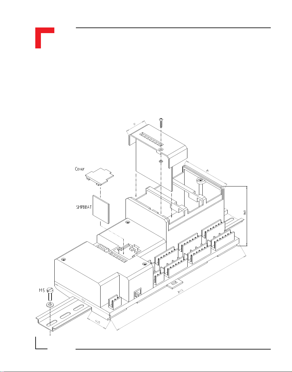
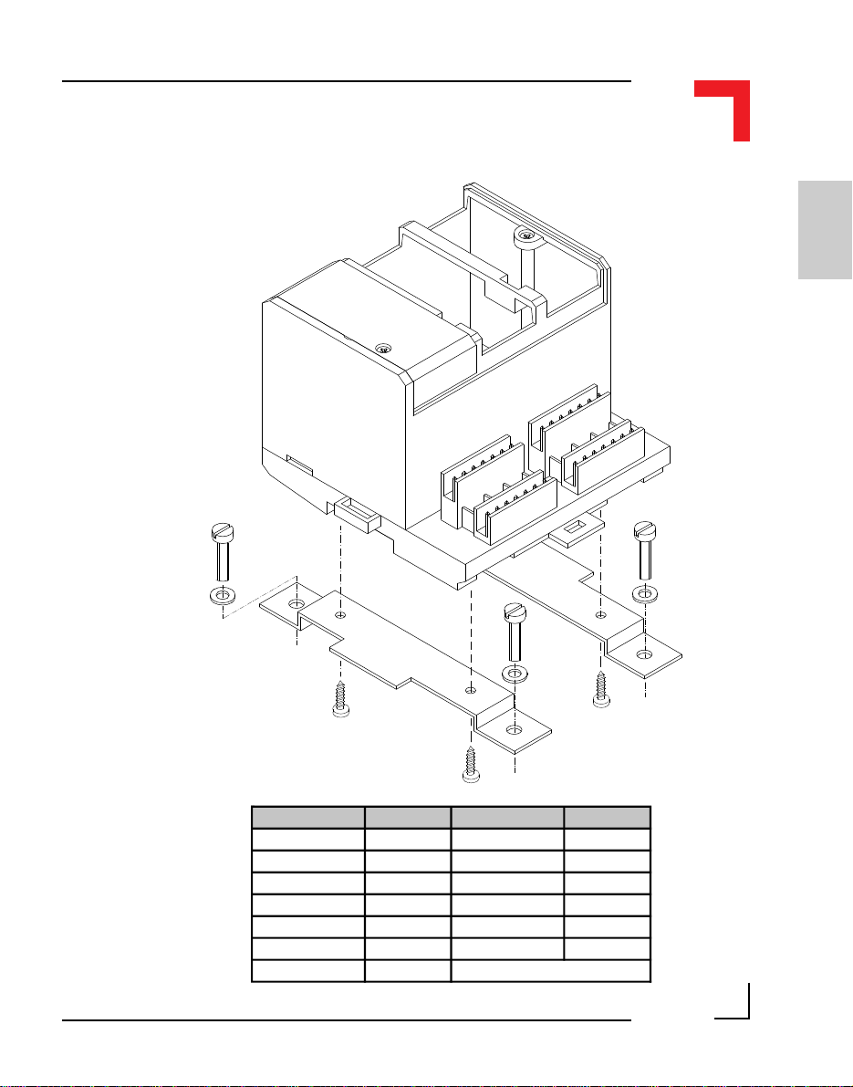
The following line drawings serve to illustrate the method of fixing the
controller to a DIN rail or brackets for wall/cabinet mounting. Note that all
measurements are in millimetres.
Introduction
Page 1 - 4
©1996 PEP Modular Computers GmbH
DIN Rail Mounting
March 12, 1996

Introduction
SMART I/O User’s Manual
1
Optional Bracket Mounting
©1996 PEP Modular Computers GmbHMarch 12, 1996 Page 1 - 5

SMART I/O User’s Manual
Introduction
Page 1 - 6
©1996 PEP Modular Computers GmbH
March 12, 1996
Introduction
SMART I/O User’s Manual
1
Unit Weight Unit Weight
SMART-BASE 650g SM-THERM 40g
SMART-EXT 250g SM-ADC1 70g
SM-DIN1 40g SM-DAC1 70g
SM-DOUT1 70g SM-SSI 70g
SM-REL1 61g SM-CNT1 N/A
SM-DAD1 70g SM-RS232 40g
SM-PT100 40g
©1996 PEP Modular Computers GmbHMarch 12, 1996 Page 1 - 7

SMART I/O User’s Manual
1.1 Product Overview
SMART I/O is based on a cost effective open system for industrial automation and industrial computing. By programming the SMART I/O using the
standard ISaGRAF workbench for IEC 1131-3 PLC programming languages
and the Ultra-C compiler (DOS, OS-9) for ANSI-C real-time programming,
the SMART I/O can be used as a micro PLC and as a real-time computer
system.
Equipped with the standard real-time fieldbus PROFIBUS, it allows the use
of the SMART I/O in a fully transparent real-time network architecture. This
architecture provides open communication between PEP systems and third
party I/O systems, as well as MMI. PROFIBUS not only allows I/O communication, but also file transfer, remote login and remote debugging facilities.
SMART I/O is designed around the MC68302 CPU from Motorola which
has two on-chip microprocessors. One is the industry standard 68HC000
running at 20MHz, and the second is a communication orientated RISC
processor. Fieldbus protocols use the power of this RISC CPU, freeing the
68HC000 for other tasks. Communication between the 68HC000 and the
communication processor is made using on-chip dual-ported RAM. Nonvolatile memory (battery backed SRAM and FLASH memory) allows a secure
and long-term backup of the application program and data.
Introduction
Well suited for machinery manufacturers and all OEMs, the SMART I/O is
an ideal companion for VME9000 and IUC9000 systems. Connected together with these high-end VME or IUC computers and PLCs, SMART I/O
allows the decentralization of I/O functions through the world wide accepted
PROFIBUS fieldbus.
SMART I/O systems provide more power than dumped remote I/O systems
since they support local intelligence: an IEC1131-3 programming environment as well as ANSI-C programming under real-time OS. All this power is
provided with excellent price/performance characteristics.
Page 1 - 8
©1996 PEP Modular Computers GmbH
March 12, 1996
Introduction
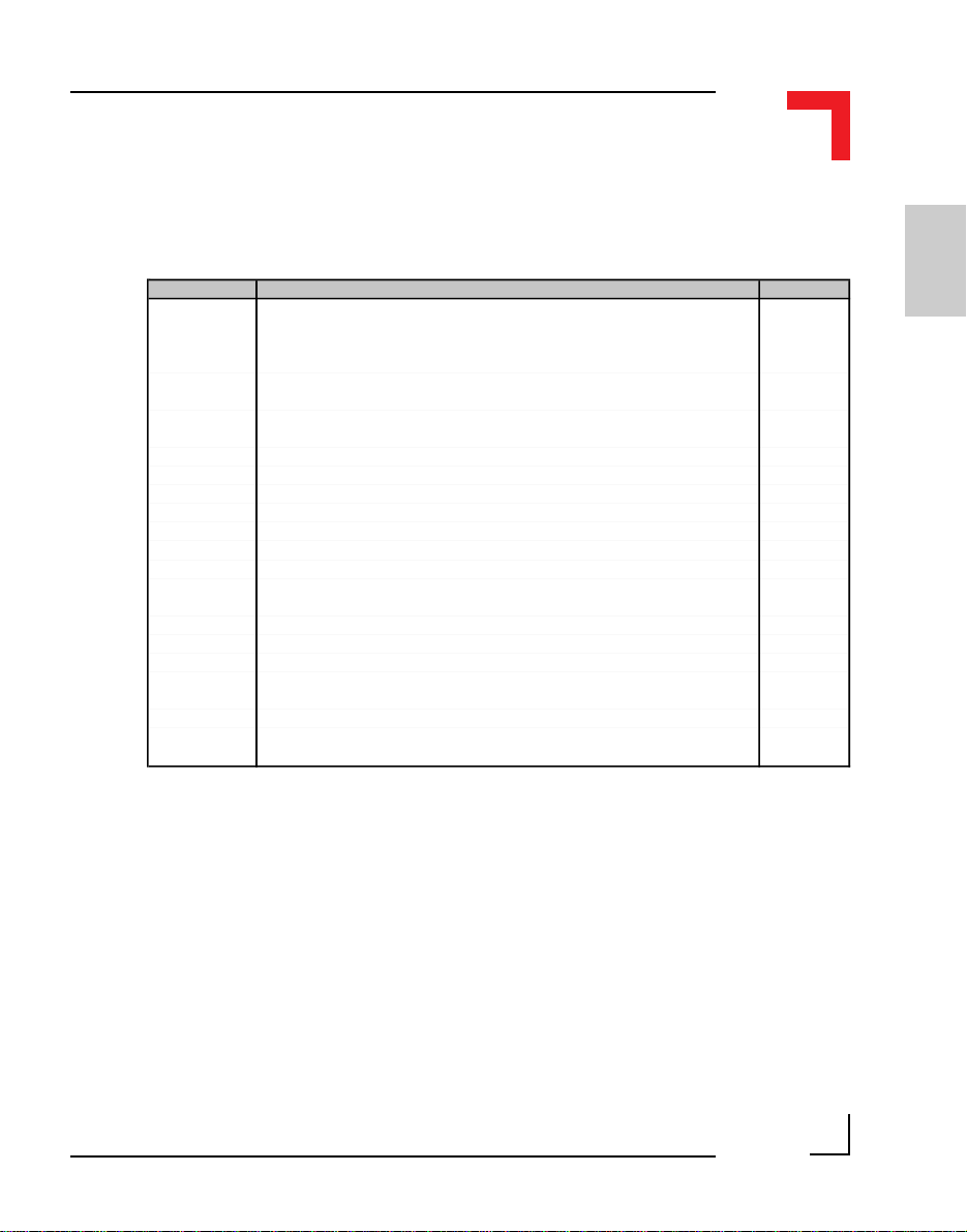
1.2 Ordering Information
SMART I/O User’s Manual
Product Description Order Nr.
SMART-BASE
SMART-BASE
SMART-EXT
SM-DIN1 SMART-Module with 8 optoisolated 24V DC digital inputs 4229
SM-DOUT1 SMART-Module with 8 optoisolated 24V DC/500mA digital outputs 4231
SM-DAD1 SMART-Module with 4 channel A/D (±10V), 2 channel D/A (±10V, 0..10V) 9868
SM-PT100 SMART-Module with 4 optoisolated 2, 3 or 4-wire PT100 inputs 12405
SM-THERM SMART-Module with 4 optoisolated thermocouple inputs 12426
SM-REL1 SMART-Module with 6 optoisolated normally open relay outputs 12238
SM-RS232 SMART-Module with RS232 (Rx & Tx) interface 12461
SM-SSI
SM-ADC1 SMART-Module with 6 12-bit, ±10V optoisolated analog inputs 13380
SM-ADC1 SMART-Module with 6 12-bit, 0..20mA optoisolated analog inputs 13868
SM-DAC1 SMART-Module with 2 12-bit, ±10V optoisolated analog outputs 13379
SM-DAC1
SM-DAC1 SMART-Module with 6 12-bit, ±10V optoisolated analog outputs 14019
SM-DAC1
Micro PLC & real-time computer, 1 MByte EPROM, 512 kByte DRAM,
64kByte SRAM, OS-9 v3.0, ISaGRAF v3.0x, PROFIBUS v3.12, Layer
2 & 7, RTC, full modem RS232 (8-pin RJ45 connector), 190 mAh
battery, housing and terminal block for the 24V DC power supply
As product 13843 but with additional 1 MByte Flash memory (TSOP) on
solder side
Expansion module for the SMART-BASE supporting 2 SMART-Modules
Delivered without terminal blocks, SMART-Modules or blank panels
SMART-Module with 1 SSI channel providing a 24V DC digital input and a
24V DC, 500mA digital output
SMART-Module with 2 12-bit, 0..20mA optoisolated analog outputs with
current sensing for broken sensor detection
SMART-Module with 6 12-bit, 0..20mA optoisolated analog outputs with
current sensing for broken sensor detection
13843
13844
4228
12825
14018
14020
1
All SM-Modules are delivered without screw terminals.
©1996 PEP Modular Computers GmbHMarch 12, 1996 Page 1 - 9

SMART I/O User’s Manual
Introduction
Product Description Order Nr.
ISaGRAFROM-START
OS9TRG-RGSMART
OS9DEVFTWIN-SMART
OS9DEVFTUNIX-SMART
OS9-PFBSMART
OS9-PFBSMART(FT)
Cable
Cable
Screw Term. For the SMART-BASE timer I/O. Pack of 5, 2x3 array 10892
SCR-2*7. For the SMART-Modules. Pack of 5, 2x7 array 10893
Dummy FP For unused SMART-Module slots. Available in packs of 20 10894
Battery
Battery
ROM kit v3.x for SMART I/O enables the generation of custom
firmware EPROMs. Platform can be a PC or OS-9 development
system
Target CPU kit for SMART I/O (OS-9 v3.x/Ix.x disks) 11299
OS-9/68000 FasTrak for Windows development pack for SMART I/O.
Contains extended OS-9 v3.x/Ix.x, PEP utilities and I/O drivers with
necessary makefiles for complete application and EPROM
generation.
OS-9/68000 FasTrak for UNIX development pack for SMART I/O.
Contains extended OS-9 v3.x/Ix.x, PEP utilities and I/O drivers with
necessary makefiles for complete application and EPROM
generation.
OS-9 PROFIBUS starter kit II for 1 node. Includes license, disk and
manual
OS-9 PROFIBUS starter kit II for 1 node operating under FasTrak for
Windows. Includes license, disk and manual
3 meters with 9-pin D-Sub (female) & RJ45 connectors for PC
operation
3 meters with 25-pin D-Sub (male) & RJ45 connectors for modem
operation
3V, 190mAh lithium batery (button) BR2032 for use in the standard
temperature range (0°C to +70°C)
3V, 850mAh lithium batery (cylinder) CR14250 for use in the
extendedtemperature range (-40°C to +85°C)
13829
13887
13926
1662
12666
10890
10891
11281
11282
1.3 Product Information
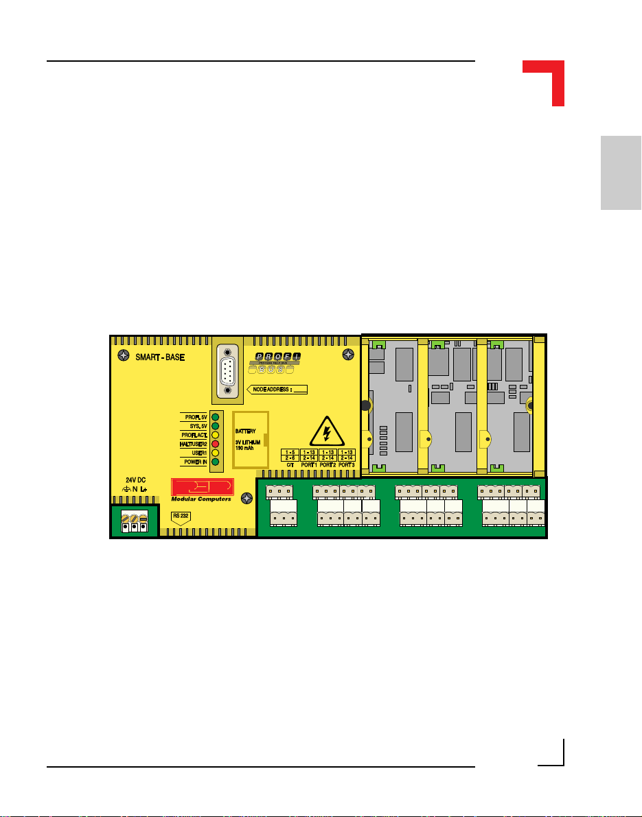
The SMART-BASE is a control module possessing an RS485 PROFIBUS
and serial RS232 interface as standard and provision for up to three SMARTModules. The modules currently available are discussed later. Normally, the
base unit is mounted on a DIN rail (see Weights & Measures section) which
in turn may be fixed in a cabinet. SMART-EXT units may be attached in a
similar manner.
Page 1 - 10
©1996 PEP Modular Computers GmbH
March 12, 1996
Introduction
SMART I/O User’s Manual
The attachment of both units is achieved by sliding them over the DIN rail
with the clip assembly pulled out and then releasing it when correctly positioned.
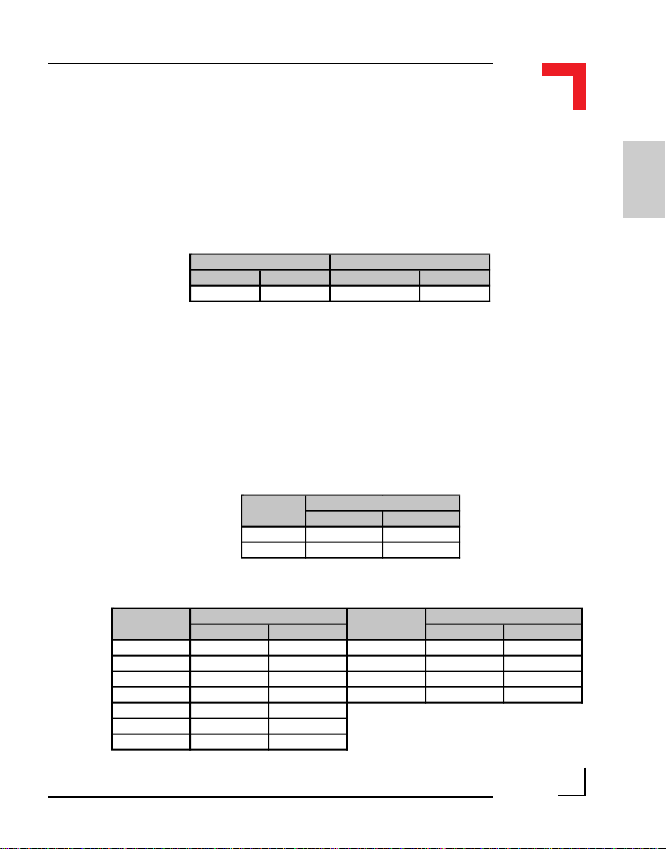
The 24V supply source should possess the following characteristics:
Voltage Current
min ma x Continuous Peak
18V 36V 400mA 1.5A (2ms)
Because of power limitations, it should be noted that although up to 11
SMART-Modules are possible in a complete configuration, attention should
be paid to the following tables that show the individual component power
requirements. The maximum of 6750mW should not be exceeded as damage
to the on-board DC-DC converter may result due to overheating or entering a
reset status due to the thermal cutoff protection switching mechanism.
1
SM-BASEPower Consumption
min max
CPU Core 1500mW 1700mW
Profibus 250mW 750mW
Module Power Consumption Module Power Consumption
min m a x min ma x
SM-DIN1 5mW 100mW SM-ADC1 350mW 450mW
SM-DOUT1 5mW 270mW SM-DAC1 5mW 400mW
SM-DAD1 350mW 450mW SM-DAC1 350mW 660mW
SM-PT100 400mW 500mW SM-SSI unknown unknown
SM-THERM 400mW 500mW
SM-RS232 23mW 75mW
SM-REL1 23mW 160mW
©1996 PEP Modular Computers GmbHMarch 12, 1996 Page 1 - 11
SMART I/O User’s Manual
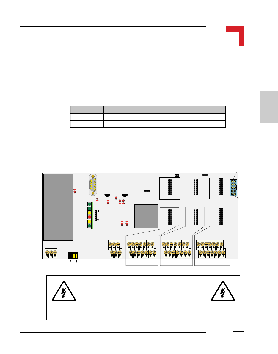
An on-board fuse protects the 24V DC input circuitry from damage through
higher voltages than those expected or AC voltages being inadvertently
applied to the system. This fuse, should it be assumed defect (the Power In
LED on the housing will not be illuminated), may be accessed by removing
the cover of the SMART-BASE and accessing the holder on the left-hand
side as shown in the illustration below.
D4
D3
C1
Introduction
F1 0.60A M
R77
SCR2
123
In the event of a blown fuse, replace it with the same size and type as the one
installed.
Page 1 - 12
©1996 PEP Modular Computers GmbH
C6
C7
March 12, 1996
Introduction
1.4 Installation
SMART I/O User’s Manual
1.4.1 Overview
The SMART-BASE and SMART-EXT units are supplied without screw
terminal blocks for the I/O slots, SMART Module piggybacks or blank
panels. These must be ordered separately to meet the requirements of individual specifications.
®
1
©1996 PEP Modular Computers GmbHMarch 12, 1996 Page 1 - 13

SMART I/O User’s Manual
Up to 4 SMART-EXT units can be cascaded depending on the power consumption of the individual SMART Modules.
Introduction
SMART I/O Modules or blank panels must be ordered separately to the
SMART-BASE or SMART-EXT units. Blank panels come in packs of 20.
Two RS232 cables are available. One terminates with a female 9-pin D-Sub
connector for PC use and the other terminates in a male 25-pin D-Sub
connector for Modem operation.
Page 1 - 14
©1996 PEP Modular Computers GmbH
March 12, 1996

Introduction
SMART I/O User’s Manual
Screw terminal connectors are available in packs of 5.
1
1.4.2 SMART I/O Module Installation
The SMART I/O Modules are fitted into the relevant sockets (ST1 - ST6; 3
slots) on the SMART-BASE or in sockets on the SMART-EXT unit. It is
important that the Modules are inserted the correct way. The Figure
below illustrates this procedure.
Figure 1.4.2.1 : SMART I/O Module Installation
SMART-Module
Socket
WARNING!
Once fitted on the board, the Module sockets and components should be on
the right hand side of the Module.
©1996 PEP Modular Computers GmbHMarch 12, 1996 Page 1 - 15
SMART-Module

SMART I/O User’s Manual
1.4.3 RJ45 Telephone Connector Installation
The RJ45 connector is fitted into the RS232 Telephone connector (BU1) on
the SMART-BASE. This is illustrated in the Figure below.
Figure 1.4.3.1 : RJ45 Telephone Connector Installation
SMART-BASE
Introduction
SCR2
BU1
RJ45 Connector
1.4.4 Screw Terminal Block Installation
The Screw Terminal Blocks are easily fitted to the SMART-BASE or
SMART-EXT by pushing them onto the relevant Screw Terminal, as shown
in the figure below.
Figure 1.4.4.1 : Screw Terminal Block Installation
Page 1 - 16
©1996 PEP Modular Computers GmbH
March 12, 1996

Introduction
SMART I/O User’s Manual
1.4.5 Battery Installation
The battery piggyback SMPBBAT is fitted into the socket BU3 on the
SMART-BASE. It is important that the piggyback is inserted in the correct
way. The figure below illustrates this procedure.
Figure 1.4.5.1: Battery Piggyback Installation
Pin 5
BU3
Pin 1
SMPBLED
SMPBBAT
Battery
Battery Type 3V Lithium BR2032 3V Lithium CR14250
Battery Capacity 190mAh 850mAh
Typical Data Retention Time *140 Days 590 Days
* this is the time without the main power being applied
WARNING!
1
Once fitted on the board, the battery should be on the right hand side of the
SMPBBAT piggyback. If the battery needs to be replaced, it must only be
done with a replacement SMPBBAT piggyback, the order number of which
is shown in the Ordering Information section of this manual.
The temperature on the battery must not exceed +70°C, due to the risk of
battery damage! For SMART I/O modules with extended temperature ranges
of up to 85°C, a special lithium battery must be fitted to the SMPBBAT.
©1996 PEP Modular Computers GmbHMarch 12, 1996 Page 1 - 17

SMART I/O User’s Manual
1.5 ISaGRAF-Installation
1.5.1 Before Installing
ISaGRAF is a Windows™ 3.xx based software development tool requiring a
minimum of 10 MB of hard disk space and 4 MB of available memory.
Before installing ISaGRAF, make a backup copy of each DOS disk in the
package and write-protect them to prevent accidental overwriting of files.
Note : The backup disks must have the same volume labels as the original
ISaGRAF disks. Use the Windows Copy Disk... command on the Disk menu
in the File Manager to create backup disks with the original volume labels
and disk contents.
If it is intended to install ISaGRAF in a directory other than the default
(C:\ISAWIN) then remember to provide the full path of the new directory
when prompted during installation.
Introduction
Altogether, 10 DOS disks and 2 OS-9 disks are supplied for ISaGRAF
installation; four for the Workbench, two composite and four for the
ISaGRAF Target and are labelled:
“Workbench Disk 1/4”
“Workbench Disk 2/4”
“Workbench Disk 3/4”
“Workbench Disk 4/4”
“Lib/Appli/Help Disk 1/2”
“Lib/Appli/Help Disk 2/2”
“Samples for OS-9 1/1”
“Target Disk 1/2” for DOS
“Target Disk 2/2” for DOS
“Profibus FMS for ISaGRAF, Documentation, Disk 1/1”
“Target Disk 1/2” for OS-9
“Target Disk 2/2” for OS-9
Page 1 - 18
©1996 PEP Modular Computers GmbH
March 12, 1996

Introduction
SMART I/O User’s Manual
1.5.2 Installation of the ISaGRAF for Windows Workbench
The following steps should be followed to ensure successful installation of
the ISaGRAF software. Initially the disk labelled Workbench Disk 1/4 will
be required.
• Start Windows
• Insert diskette Workbench Disk 1/4 into the floppy drive (usually A:)
• Select File from the Windows Program Manager and select Run ...
• Type A:\INSTALL in the command field and select OK
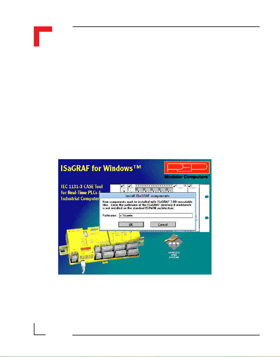
The ISaGRAF installation will start automatically. Figure 1.5.2.1 illustrates a
typical opening screen.
1
Figure 1.5.2.1 Typical Opening Screen
©1996 PEP Modular Computers GmbHMarch 12, 1996 Page 1 - 19
SMART I/O User’s Manual
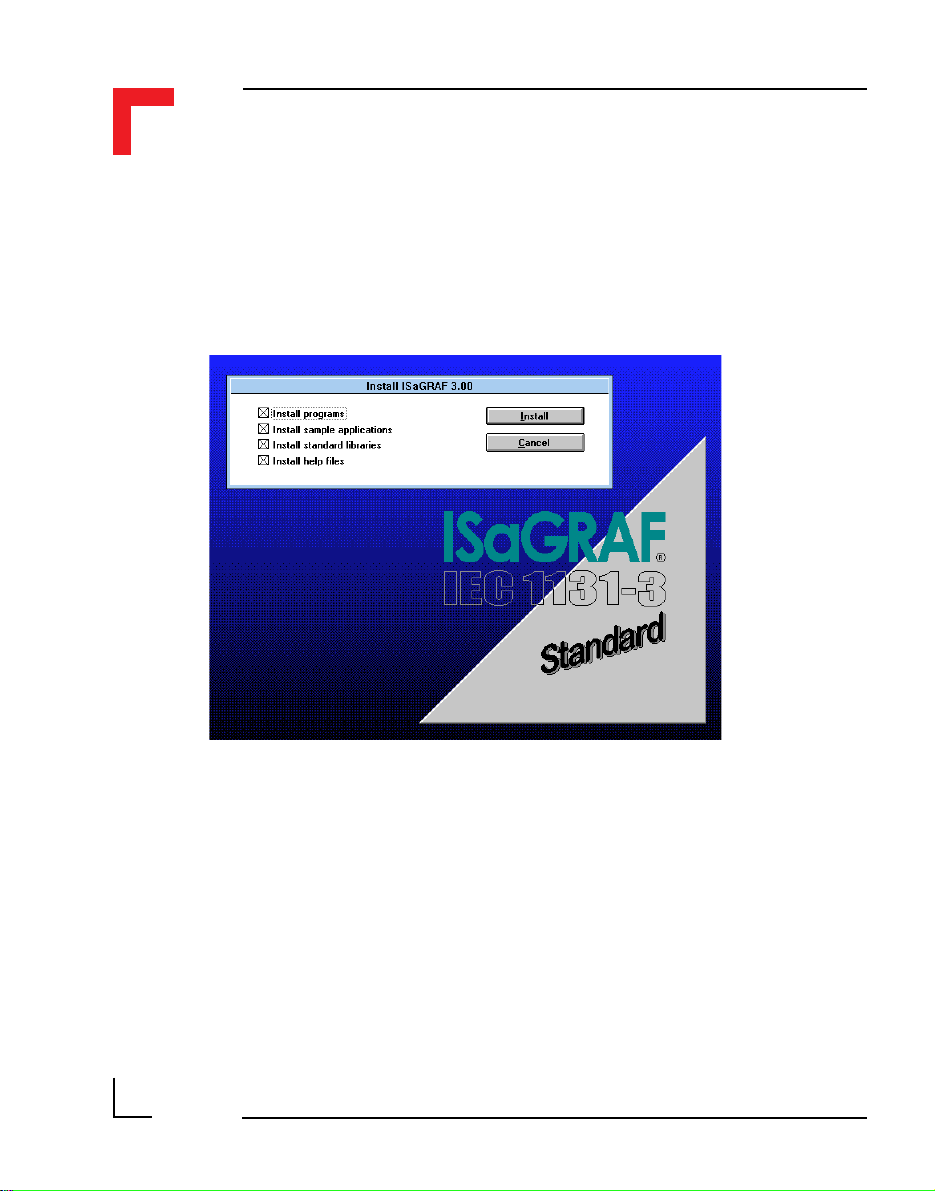
Having checked the installation directory (default is C:\ISAWIN) and
selected Install, the program progresses by asking whether the complete
system should be installed or just certain sections. The selection possibilities
are shown in figure 1.5.2.2.
Introduction
Figure 1.5.2.2 Installation Selection
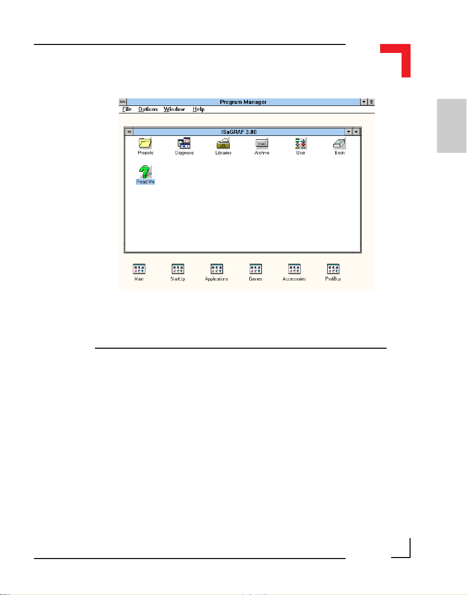
The default is for a complete installation, i.e. all files. Once confirmed, the
installation copies the required files to the installation directory and unpacks
their contents. This procedure will take a few minutes. Upon completion, the
windows desktop will show a new program group containing the files shown
in figure 1.5.2.3.
Page 1 - 20
©1996 PEP Modular Computers GmbH
March 12, 1996
Introduction
SMART I/O User’s Manual
1
Figure 1.5.2.3 ISaGRAF Program Group
1.5.3 Installation of PEP Library Functions
The library functions are adapted to suit the SMART I/O and other PEP
products and should be installed using the two diskettes labelled LIB/
APPLI/HELP.
©1996 PEP Modular Computers GmbHMarch 12, 1996 Page 1 - 21
SMART I/O User’s Manual
These libraries for projects, I/O boards, ’C’ functions and common data are
extracted by following the described procedure:
• Start Windows if not already started
• Insert diskette Lib/Appli/Help Disk 1/2 into the floppy drive
• Select File from the Windows Program Manager and select Run ...
• Type A:\INSTALL in the command field and select OK
Figure 1.5.3.1 illustrates the Installation Start-up screen.
Introduction
Page 1 - 22
Figure 1.5.3.1 The Installation Start-up Screen
©1996 PEP Modular Computers GmbH
March 12, 1996

Introduction
SMART I/O User’s Manual
It should be noted that the standard ISA-Terminal is configured for COM2. If
another port is required then the switch to the new one is made by firstly
starting the ISA-Terminal program and then selecting the Settings from the
Communication pull-down menu. Here the possibility exists to select the
desired communications port. When leaving the ISA-Terminal environment,
remember to save the configuration if changes have been made.
The installation of the ISaGRAF development tool is now complete and
access is provided to a full IEC1131-3 programming platform.
The following sections deal with the application of this tool with the SMART
I/O and other PEP PLCs. Note that ‘C’ programming is not an option for the
SMART I/O Starter Kit and if required must be ordered separately through
one of the PEP offices or agents.
1
©1996 PEP Modular Computers GmbHMarch 12, 1996 Page 1 - 23
SMART I/O User’s Manual
In order to verify that the hardware and software have been correctly setup,
the following procedure should be followed.
• Connect the D-Sub connector end of the terminal cable to the chosen
COM port of the computer. The other end, with the telephone type
connector should be pushed into place in the RS232-port of the
SMART I/O base (see figure 1.4.3.1)
• With the power supply turned OFF, connect the power plug to SCR-2
on the SMART base.
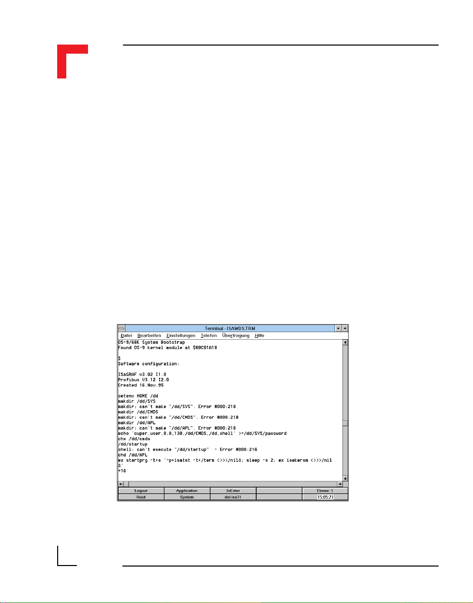
• Start the ISA-Terminal program.
• Switch on the power supply to the SMART I/O; three green LEDs
should illuminate on the control panel (not the SMART Modules!). The
terminal should display the messages shown in figure 1.5.3.2.
Introduction
Page 1 - 24
Figure 1.5.3.2 Power Up Messages
©1996 PEP Modular Computers GmbH
March 12, 1996

Introduction
SMART I/O User’s Manual
The error messages that are shown in figure 1.5.3.2 are normal as the system
is trying to create files or directories in the RAM disk that are already
present.
If no further messages appear, then the installation is complete. Should the
terminal result in anything different than shown then check through the
installation steps again before contacting PEP for help.
The three green LEDs mentioned earlier show the state of
• PROFIBUS 5V
• System 5V and
• Power ON
1
©1996 PEP Modular Computers GmbHMarch 12, 1996 Page 1 - 25
SMART I/O User’s Manual
1.5.4 Demo Application
Several demonstration applications are delivered with the ISaGRAF set of
disks and are installed automatically. The applications suitable for use with
the SMART I/O are prefixed SM- and serve to show how the SMART I/O
can be used through practical examples. Two such programs, the SM-
DEMO1 and 2 are discussed here :
SM_DEMO1 should be used if the SMART I/O has the SM_DOUT1
module in the first of the SMART Module slots and has SM_DIN1 in slot 2
(the last) on the SMART-BASE.
SM_DEMO2 should be used if the modules are reversed.
To install the demonstrations correctly, observe the following procedure and
make sure the correct diskette is in place :
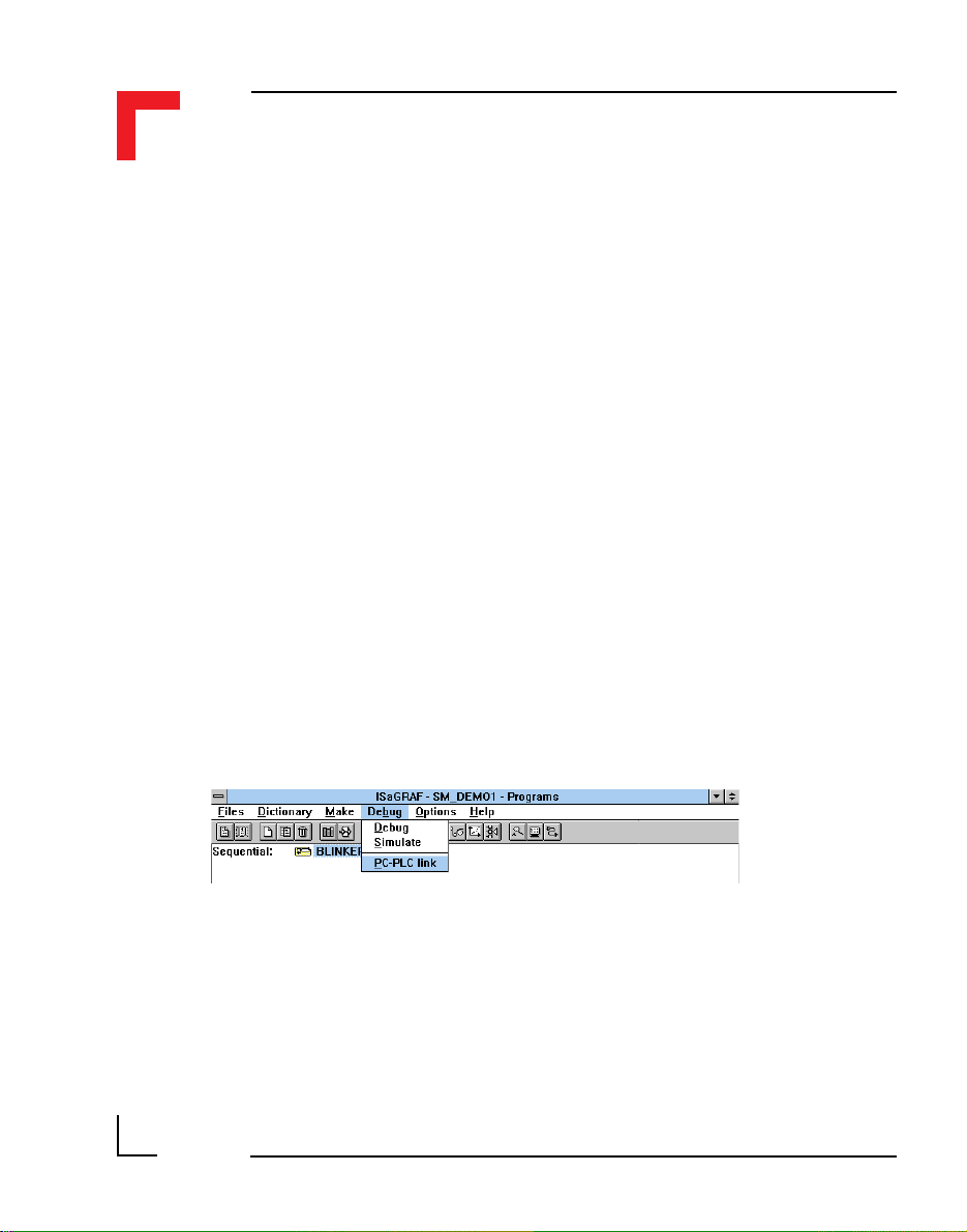
•Run the Projects Program and select SM_DEMO1 or SM_DEMO2 by
double clicking on the icon;
Introduction
•Go to the Debug/PC-PLC Link Menu to ensure that the correct COM
port is selected for communication to the SMART I/O;
•When confirmed, select Debug/Debug;
•From the Debugger Window, select File from the pull-down
menu if an application is already executing (indicated by Run in the
status line);
Page 1 - 26
©1996 PEP Modular Computers GmbH
March 12, 1996

Introduction
SMART I/O User’s Manual
• Finally, from the Files/Download pull-down menu, select
Motorola Target Code.
The chosen SM_DEMO will be downloaded to the SMART I/O (target
system) and the application will begin automatically.
1
This is a simple SFC-program which will activate channel 7 of the SMDOUT1 when the first SFC-step (init) is encountered thereby illuminating
the diode. During the next cycle, step 2 is encountered and activates channel
2 and at the same time deactivates channel 3. The program will wait for 1
second in this state before reversing the action. The effect is that the second
and third LED illuminate alternately with a pause of 1 second between.
©1996 PEP Modular Computers GmbHMarch 12, 1996 Page 1 - 27

SMART I/O User’s Manual
This page has been left blank intentionally.
Introduction
Page 1 - 28
©1996 PEP Modular Computers GmbH
March 12, 1996

Chapter 2 SMART-BASE
2. SMART-BASE.........................................2-3
2.1 Specifications ......................................................................... 2-4
2.2 Board Overview ..................................................................... 2-5
2.3 Functional Description........................................................... 2-6
2.4 Configuration ......................................................................... 2-8
2.4.1 Jumper J1: Boot Selection (Pin Connector) ........................................ 2-8
2.4.2 Jumper J6: LED Function (Pin Connector) ......................................... 2-9
2.5 Pinouts ................................................................................... 2-9
2.5.1 SMART Module Piggyback Connectors........................................... 2-10
2.5.2 Screw Terminal Pinouts .................................................................... 2-12
2.5.3 Timer I/O Screw Terminal (SCR1) ...................................................2-12
2.5.4 Supply Screw Terminals (SCR2) ...................................................... 2-14
2.5.5 RS232 Telephone Connector (BU1) .................................................2-15
2.5.6 RS485 D-Sub Connector for Half-Duplex Operation (Profibus) ...... 2-15
2.5.7 SPI Connector (ST7) ......................................................................... 2-16
2.6 ‘C’ Programming ................................................................. 2-17
2.6.1 SMART-BASE Library ..................................................................... 2-17
2.6.2 SMTselIn ...........................................................................................2-18
2.6.3 SMTsettout ........................................................................................2-20
2.6.4 SMTpre .............................................................................................2-21
2.6.5 SMTstasto.......................................................................................... 2-23
2.6.6 SMTrd ............................................................................................... 2-24
2.6.7 SMTtin .............................................................................................. 2-25
2.6.8 SMTstat ............................................................................................. 2-26
2.6.9 SMTout.............................................................................................. 2-27
2.6.10 SMLed .............................................................................................2-28
2.6.11 SMwdon .......................................................................................... 2-29
2.6.12 SMwdtrig ......................................................................................... 2-30
2.6.13 SMwdoff .........................................................................................2-31
SMART I/O User’s Manual
Table of Contents
2
©1996 PEP Modular Computers GmbHMarch 12, 1996 Page 2 - 1

SMART I/O User’s Manual
Chapter 2 SMART-BASE
2.7 ISaGRAF Programming ...................................................... 2-32
2.7.1 The ISaGRAF Board Parameters ...................................................... 2-32
2.7.2 The ISaGRAF Operate Calls............................................................. 2-33
2.8 Flash Utility ......................................................................... 2-37
Page 2 - 2
©1996 PEP Modular Computers GmbH
March 12, 1996

Chapter 2 SMART-BASE
2. SMART-BASE
The SMART-BASE is the main unit to which up to three SMART-Modules
may be connected to fulfil a given I/O task with I/O enhancement being
provided through the connection of a SMART-EXT unit which itself may
accommodate up to 2 SMART-Modules. A counter/timer is also a standard
feature providing direct access to IRQ4 of the I/O controller. The driving
force behind the SMART-BASE is the MC68302 microprocessor from
Motorola operating at 20MHz.
The SMART-BASE, complete with built-in RS232 and RS485 (PROFIBUS)
interfaces is connected to the outside world by RJ45 and 9-pin D-Sub
connectors respectively. Connected SMART-Modules use industrial standard, plug-in screw terminals.
Program code is stored in EPROM or FLASH memory thereby doing away
with disk accesses and ensuring data security in harsh industrial environments. A SMART-BASE unit with additional 1MByte FLASH memory may
be ordered as an option in which to extend the standard code and supply
user-specific functionality.
SMART I/O User’s Manual
2
©1996 PEP Modular Computers GmbHMarch 12, 1996 Page 2 - 3

SMART I/O User’s Manual
2.1 Specifications
Nominal Input Voltage 24V DC
Input Voltage Range 18V - 36V DC
Input Current
Main Output Voltage 5V DC / 1.2A ± 2.5%
Auxiliary Output Voltage 5V DC / 150mA (PROFIBUS/RS485) ± 5%
Switching Frequency 100kHz
Main Output Ripple ± 10mV typ.
Max. Efficiency 68% typ. (between 74% and 100% load)
Galvanic Isolation 500V DC max. to/from supply source
CPU MC68302 @ 20MHz
EPROM or FLASH*
FLASH*
DRAM 512 kByte, byte/word access (16-bit)
SRAM 64 kByte, byte/word access (16-bit)
EEPROM 93C46, 32-byte system data
Galvanic Isolation 2.5kV DC to/from process I/O
Temperature Range
- Storage
- Operating
- Extended
Operating Humidity 0 to 95% non-condensing
Weight 640g typ. without SMART-Modules, blank
Chapter 2 SMART-BASE
DC/DC
140mA typ. @ 24V (static)
400mA typ. @ 24V (full load)
Controlling Unit
1 MByte or 256 kByte on Jedec 32-pin
sockets (16-bit access)
1 MByte or 256 kByte additionally soldered
on rear side of the board (16-bit access)
Common
-40°C to + 85°C (without battery)
0°C to +70°C
-40°C to +85°C
panels or screw terminals
* Option
Page 2 - 4
©1996 PEP Modular Computers GmbH
March 12, 1996

Chapter 2 SMART-BASE
2.2 Board Overview
Front view
RS485 Isolated
(PROFIBUS)
SMART I/O User’s Manual
J13 J1
ST5 ST3 ST1 ST7
SPI
DC/DC
24V DC
Rear View
BU2
Status
Piggyback
SMPBLED
Battery
Piggyback
SMPBBAT
RS232
BU1SCR2 SCR1 SCR5 SCR4 SCR3
DRAM
UD LD
EPROM/FLASH
BU3
EPROM/FLASH
Timer
I/O
(SRAM)
RTC Quartz
J6
68302FC20
RTC
I/O Controller
ST6 ST4 ST2
SMART Modules
I/O Slot #2I/O Slot #1I/O Slot #0
2
1
J15
3
Full DUPLEX RS485
(Option)
2
Optional
FLASH
RS232 Driver
©1996 PEP Modular Computers GmbHMarch 12, 1996 Page 2 - 5

SMART I/O User’s Manual
2.3 Functional Description
Figure 2.3.0.1: SMART I/O Block Diagram
Chapter 2 SMART-BASE
Clock
Generators
Serial Interfaces
RS485
RS232
DC/DC
I/O Controller
Timer/Counter
Interface
MCU
MC68302
@ 20 MHz
SMART-Module
Interface
The MCU, an MC68302 microprocessor operating at 20 MHz is responsible
for handling all communication between the various interfaces and on-board
memory.
An RS485 highspeed PROFIBUS 2-wire interface is optically isolated from
the system and may be configured for full duplex operation (a 4-wire interface available on request for OEM volume). Likewise, a fully configured
RS232 modem interface is available for program downloading for example
on SMART I/O systems supporting FLASH memory for this task or to the
RAM disk etc.
Memory
FLASH
EPROM
SRAM
SPI
Interface
Page 2 - 6
©1996 PEP Modular Computers GmbH
March 12, 1996

Chapter 2 SMART-BASE
The isolated DC/DC converter is based on a switched mode regulating
system operating at 100 kHz and supplies power to both the system and the
isolated RS485 (PROFIBUS) interface.
The SPI interface, a 3-wire communication protocol providing SCLK, RxD
and TxD is embedded within a larger 10-wire interface for handling communication between the base unit and SMART-Modules attached either directly
or on extension units.
Up to three SMART-Modules are supported on the SMART-BASE unit with
connection to the outside world being provided by industrial standard screw
terminals. The same calibre of terminal is used for the counter/timer, which
is directly coupled to the system I/O controller. A more detailed description
of the counter/timer appears in the pinout section of this chapter.
Figure 2.3.0.2 shows the interrupt handling capability of the I/O controller. It
should be noted that the controller can only be programmed with the use of a
PEP defined software protocol that ensures compatibility in case of hardware
changes.
SMART I/O User’s Manual
2
Figure 2.3.0.2 IRQ Capabilities
Smart Base
Smart
Smart
Module
Module
IRQ
IRQ
Int 1
Int 2
Interrupt
I/O
Timer
Logic
IRQ 4
©1996 PEP Modular Computers GmbHMarch 12, 1996 Page 2 - 7
Smart
Module
IRQ
Int 3
IRQ 1
1st Smart Ext
Smart
Module
IRQ
Int 4
Smart
Module
Programmable

SMART I/O User’s Manual
Chapter 2 SMART-BASE
2.4 Configuration
The SMART BASE has 2 configurable jumpers which are explained in the
following sections. The jumper settings marked in italics in the tables are
default.
Figure 2.4.0.1: SMART BASE Jumper Layout (Front View)
RS485 Isolated
(PROFIBUS)
J13 J1
ST5 ST3 ST1 ST7
SPI
DC/DC
24V DC
BU2
Status
Piggyback
SMPBLED
Battery
Piggyback
SMPBBAT
RS232
BU1SCR2 SCR1 SCR5 SCR4 SCR3
DRAM
UD LD
EPROM/FLASH
BU3
EPROM/FLASH
Timer
I/O
(SRAM)
J6
68302FC20
I/O Controller
ST6 ST4 ST2
SMART Modules
I/O Slot #2I/O Slot #1I/O Slot #0
2.4.1 Jumper J1: Boot Selection (Pin Connector)
The jumper J1 selects whether the SMART I/O boots directly from OS-9 or
from ISaGRAF.
Jumper J1 Description
1-3 Application Boot (ISaGRAF)
1-2 OS-9 Shell Boot
Page 2 - 8
©1996 PEP Modular Computers GmbH
March 12, 1996
Chapter 2 SMART-BASE
2.4.2 Jumper J6: LED Function (Pin Connector)
This jumper selects the function of the red LED; halt or user defined. The
user defined function that is supported in software will only take effect if this
jumper is set accordingly.
SMART I/O User’s Manual
Jumper J6 Description
1-3 Processor HALT function monitor
1-2 User defined function
2.5 Pinouts
Figure 2.5.0.1: SMART-BASE Connector Overview
Pin 5
Pin 9
DC/DC
SCR2
Pin 1 Pin 2 Pin 3
BU2
Pin 6
B17
SMPBLED
BU1
Pin 1
Pin 8
B8
Pin 1
UD LD
B10
Pin 5
BU3
Pin 1
EPROM/FLASH
B7
B11
B16 B1
Pin 1
Pin 5
Pin 2
Pin 6
SCR1
B9
68302FC20
Pin 1
Pin 2
Slot #0 Slot #1 Slot #2
SCR5 SCR4 SCR3
ST5
J6
Slot #0 Slot #1 Slot #2
ST6
Pin 1
Pin 13
Pin 2
Pin 14
2
J13
Pin 15Pin 16
ST3
Pin 1Pin 2
Digital Side
Process SIde
Pin 15Pin 16
ST4
Pin 1Pin 2
Pin 13
Pin 14
J1
Pin 15Pin 16
ST1
Pin 1Pin 2
Pin 15Pin 16
ST2
Pin 1Pin 2
Pin 1
Pin 2
Pin 1
Pin 15Pin 16
Pin 2
ST7
Pin 1Pin 2
Pin 10
Pin 9
Pin 15Pin 16
Pin 1Pin 2
Pin 13
Pin 14
WARNING !
Dangerous voltages may be present at the terminals.
©1996 PEP Modular Computers GmbHMarch 12, 1996 Page 2 - 9
SMART I/O User’s Manual
Chapter 2 SMART-BASE
Note
Slot# numbers are counted from #0 up to #10 while the ISaGRAF logic
counts from #1 to #11!
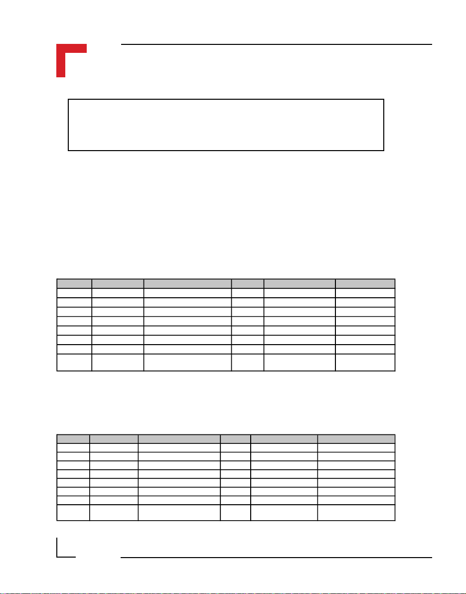
2.5.1 SMART Module Piggyback Connectors
There are three sets of SMART Module piggyback connectors available on
the SMART-BASE, each divided into two sets of 2x8 standard pin rows.
Pinouts digital side (ST1, ST3 and ST5)
SMART-Module location #0 (ST5) pinouts
Pin Nr. Signal Description Pin Nr. Signal Description
1 PA8 68302 Port A8 2 PA9 68302 Port A9
3 PA10 68302 Port A10 4 PA11 68302 Port A11
5 PA12 68302 Port A12 6 PA13 68302 Port A13
7 PA14 68302 Port A14 8 PA15 68302 Port A15
9 System GND GND 10 Serial RxD RxD
11 System VCC 5V VCC 12 Serial TxD TxD
13 CS-SM1 Port Select (Module 0) 14 Serial CLK CLK
15 Reset Reset (Power ON/OFF) 16 SM1 Interrupt PI/T
INT3 to the
I/O Controller
SMART-Module location #1 (ST3) pinouts
Pin Nr. Signal Description Pin Nr. Signal Description
1 PITB0 I/O Controller Port B0 2 PITB1 I/O Controller Port B1
3 PITB2 I/O Controller Port B2 4 PITB3 I/O Controller Port B3
5 PITB4 I/O Controller Port B4 6 PITB5 I/O Controller Port B5
7 PITB6 I/O Controller Port B6 8 PITB7 I/O Controller Port B7
9 System GND GND 10 Serial RxD RxD
11 System VCC 5V VC C 12 Serial TxD TxD
13 CS-SM2 Port Select (Module 1) 14 Serial CLK CLK
15 Reset Reset (Power ON/OFF) 16 SM2 Interrupt PI/T
Page 2 - 10
©1996 PEP Modular Computers GmbH
INT2 to the
I/O Controller
March 12, 1996
Chapter 2 SMART-BASE
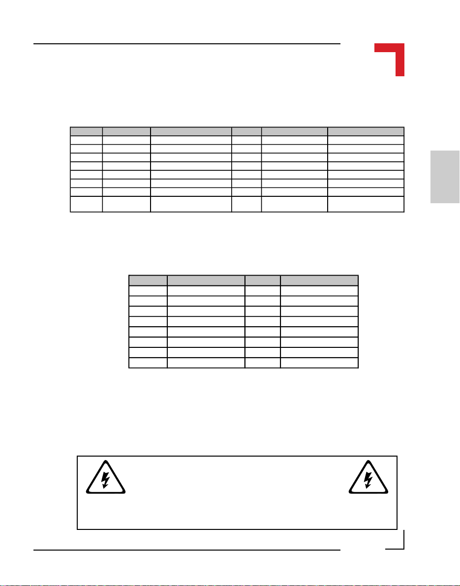
SMART-Module location #2 (ST1) pinouts
Pin Nr. Signal Description Pin Nr. Signal Description
1 PITA0 I/O Controller Port A0 2 PITA1 I/O Controller Port A1
3 PITA2 I/O Controller Port A2 4 PITA3 I/O Controller Port A3
5 PITA4 I/O Controller Port A4 6 PITA5 I/O Controller Port A5
7 PITA6 I/O Controller Port A6 8 PITA7 I/O Controller Port A7
9 System GND GND 10 Serial RxD RxD
11 System VCC 5V VC C 12 Serial TxD TxD
13 CS-SM3 Port Select (Module 2) 14 Serial CLK CLK
15 Reset Reset (Power ON/OFF) 16 SM3 Interrupt PI/T
Pinouts process side (ST6, ST4 and ST2) for Modules #0 to #2
Pin Nr. Signal Pin Nr. Signal
1 Screw Terminal 13 2 Screw Terminal 13
3 Screw Terminal 1 4 Screw Terminal 2
5 Screw Terminal 3 6 Screw Terminal 4
7 Screw Terminal 5 8 Screw Terminal 6
9 Screw Terminal 7 10 Screw Terminal 8
11 Screw Terminal 9 12 Screw Terminal 10
13 Screw Terminal 11 14 Screw Terminal 12
15 Screw Terminal 14 16 Screw Terminal 14
SMART I/O User’s Manual
INT1 to the
I/O Controller
2
The PC board connections to the screw terminals are capable of absorbing a
continuous current of up to 3A each. However, pins 13 and 14 can support
up to 6 Amps.
WARNING !
Dangerous voltages may be present at the terminals.
©1996 PEP Modular Computers GmbHMarch 12, 1996 Page 2 - 11
SMART I/O User’s Manual
Chapter 2 SMART-BASE
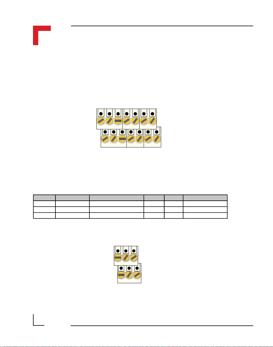
2.5.2 Screw Terminal Pinouts
The following shows the pinout for a screw terminal block suited for use
with SMART-Modules. The pinouts of these blocks depends on the SMART
Modules that are fitted.
Pin 1
Pin 2
Pin 13
Pin 14
2.5.3 Timer I/O Screw Terminal (SCR1)
Pin Nr. Signal Description Pin Nr. Signal Description
1 External VCC 5V VCC 2 TOUT Timer OUT
3 External GND Ground for TIN, TOUT 4 TIN Timer IN
5 External GND Ground for TGATE 6 GATE GATE Connection
Pin 1
Pin 5
Page 2 - 12
Pin 2
Pin 6
©1996 PEP Modular Computers GmbH
March 12, 1996

Chapter 2 SMART-BASE
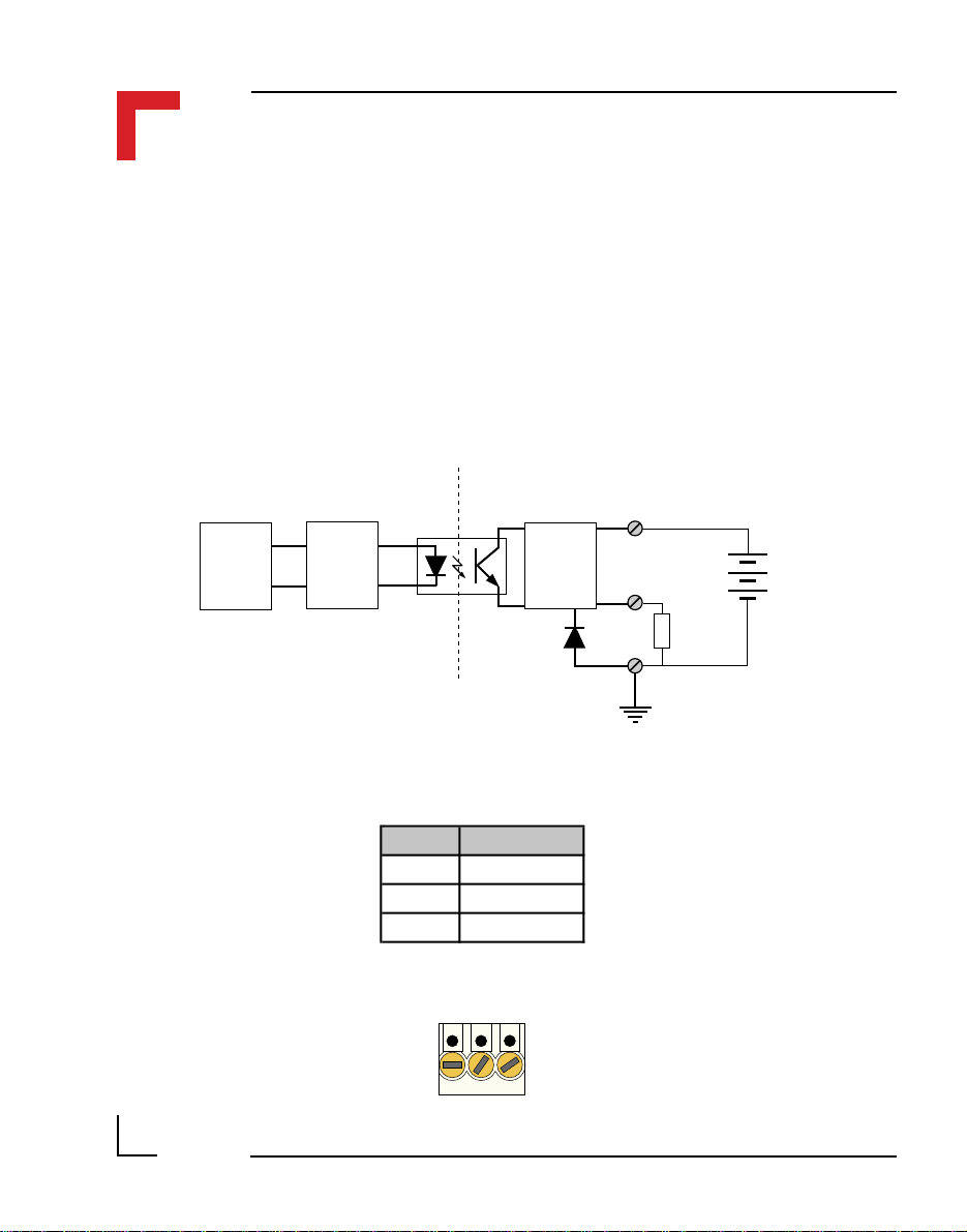
To understand the functionality of the counter/timer, it is necessary to
understand the purpose of TIN, TOUT and TGATE. Figure 2.5.3.1 shows
the block diagram of TIN.
Figure: 2.5.3.1 Timer I/O (TIN) Schematic
SMART I/O User’s Manual
+Vcc (24V)
1
TINGATE
Gnd (common)
+Vcc (24V)
Gnd (common)
4
3
1
6
5
Input
Circuit
Input
Circuit
Low
Pass
Filter
Low
Pass
Filter
Digital
Input
Timer I/O
TIN
GATE
The I/O Controller timer is used for the generation of the TOUT and TIN
functions with the three timer I/O lines being fully isolated from the system.
The internal clock of the timer/counter is 6MHz and can be prescaled to
enable lower frequencies as necessary.
With the GATE permanently active (relay closed), every pulse detected on
the TIN line will be acknowledged up to a frequency of 20kHz. Otherwise,
TIN will only be recognized for the duration that the GATE is active.
2
©1996 PEP Modular Computers GmbHMarch 12, 1996 Page 2 - 13
SMART I/O User’s Manual
Chapter 2 SMART-BASE
Figure 2.5.3.2 shows the TOUT block diagram. Here, the output is only
active when an interrupt on level 4 has been acknowledged by the I/O
controller or a previously set timer has decremented to 0. The driving stage
of the output consists of a Darlington connected transistor pair protected
from inductive loads by a clamp diode. This TOUT line can generate squarewave pulses from 0.2ms to 178ms and can deliver 500mA continuously at
24V DC. The maximum frequency of TOUT is 5kHz.
Figure 2.5.3.2: Timer I/O (TOUT) Schematic
+Vcc (common)
Timer I/O
TOUT
Digital
Output
2.5.4 Supply Screw Terminals (SCR2)
Pin Nr. Signal
1 SHIELD
2 GND
3 +24V
Pin 1
Pin 3
Output
Stage
1
2
Load
3
Gnd
Page 2 - 14
©1996 PEP Modular Computers GmbH
March 12, 1996

Chapter 2 SMART-BASE
2.5.5 RS232 Telephone Connector (BU1)
In order to meet the needs of widespread standards, the RS232 connector is
selected as a telephone connector, an 8-pin RJ12 telephone jack with full
MODEM support.
SMART I/O User’s Manual
Pin Nr. Signal Description
1 DSR Data Set Ready
2 RTS Ready to Send
3 System GND System GND
4 TxD Transmit Line
5 RxD Receive Line
6 DCD Data Carrier Detect
7 CTS Clear to Send
8 DTR Data Terminal Ready
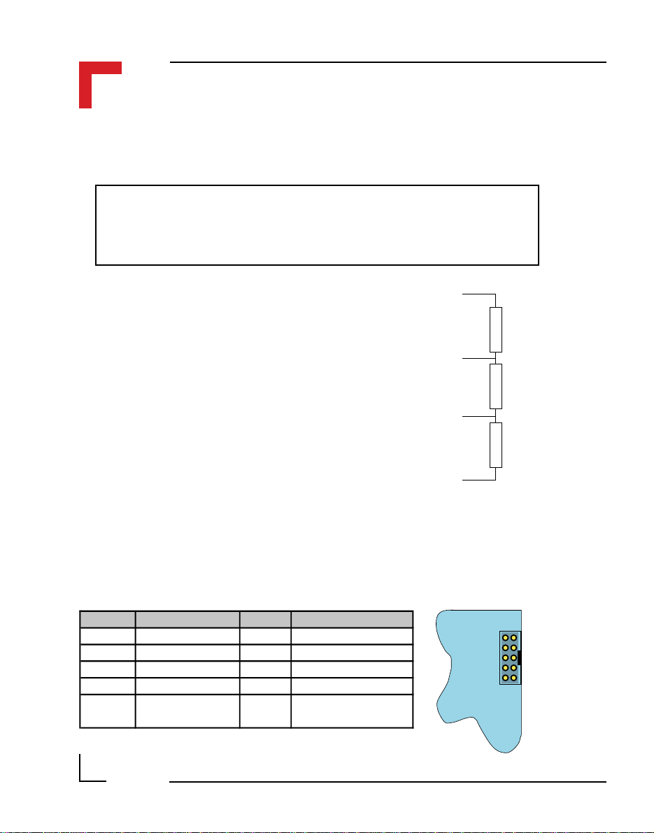
2.5.6 RS485 D-Sub Connector (BU2) for Half-Duplex Operation (Profibus)
Pin Nr. Signal Description Pin Nr. Signal Description
1 SHIELD Shield Isolation 6 Aux. +5V Auxiliary +5V
2 N/C Not Connected 7 N/C Not Connected
3 T/RxD + Transmit / Receive Line 8 T/RxD - Transmit / Receive Line
4 CNTR +* Control Line 9 CNTR -* Control Line
5 Aux. GND Auxiliary Ground
* optional, for full-duplex operation
12 8
2
9
6
©1996 PEP Modular Computers GmbHMarch 12, 1996 Page 2 - 15
5
1
SMART I/O User’s Manual
Chapter 2 SMART-BASE
The full-duplex description may be found in the SMART-I/O Advanced
User’s Guide.
Note
There is no internal line termination as laid down in DIN 19245 Part 1
and must be performed externally.
Aux. +5V, 90mA
The line termination is achieved as shown in
the figure. Assuming a power supply voltage
of +5V emanating from the PROFIBUS
connector (pin 6), the following resistor
T/RxD +
values are recommended.
R
150Ω ± 2%, min 0.25W
t
R
390Ω ± 2%, min 0.25W
U
R
390Ω ± 2%, min 0.25W
d
T/RxD -
Ru = 390Ω
t
= 150Ω
R
d
= 390Ω
R
Aux. GND
2.5.7 SPI Connector (ST7)
The SPI connector is a 2x5 standard pinrow connector, located on the righthand side of the SMART-BASE to enable easy connection of the SMARTEXT module using a flat ribbon cable connection.
Pin Nr. Signal Pin Nr. Signal
1 System VCC 2 Serial RxD
Pin 1 Pin 2
3 System VCC 4 Serial TxD
5 Serial Ext. Select 6 Serial CLK
7 System GND 8 Reset
9 System GND 10
Page 2 - 16
©1996 PEP Modular Computers GmbH
Serial Ext. Interrupt
(Controller I/O IRQ4)
Pin 9 Pin 10
SMART-BASE
ST7
March 12, 1996

Chapter 2 SMART-BASE
2.6 ‘C’ Programming
2.6.1 SMART-BASE Library
The SMART-BASE library of functions smartio.l provide a convenient way
of accessing various features of the SMART-BASE.
• All functions are written in ANSI C;
• Prototypes are to be found in the file BSP/SMART/DEFS/SMAC.h.
Hardware Requirements
• SMART I/O Base Module.
Software Requirements
The compiler from one of the following:
SMART I/O User’s Manual
2
• Ultra C Version 1.1.2 or higher;
• FasTrak 2.0.2 or higher.
The examples provided here are primarily concerned with the timer/counter.
Other aspects of SMART BASE programming may be found in the Advanced User’s guide.
©1996 PEP Modular Computers GmbHMarch 12, 1996 Page 2 - 17

SMART I/O User’s Manual
2.6.2 SMTselIn
Syntax
error_code SMTselIn(u_int8 mode);
Description
This function selects one of four possible counter/timer input (TIN) configurations utilizing the 6MHz internal counter/timer clock.
Input
Chapter 2 SMART-BASE
u_int8 mode
This represents the four input configurations. They
are:
MODE00
the Simple I/O and the CLK and prescaler are used.
The prescaler is decremented on the falling transition
of the clock pin; the 24-bit counter is decremented,
rolls over or is loaded from the counter preload
registers when the prescaler rolls over from $00 to
$1F.
MODE01
input and the CLK and prescaler are used. The
prescaler and counter are decremented as in
MODE00.
MODE10
timer input and the prescaler is used. The prescaler is
decremented following the rising transition of the
TIN pin after being synchronized with the internal
clock. The 24-bit counter is decremented, rolls over
or is loaded from the counter preload registers when
the prescaler rolls over from $00 to $1F.
The Simple I/O/TIN input pin carries
The Simple I/O/TIN serves as a timer
The Simple I/O/TIN pin serves as a
Page 2 - 18
©1996 PEP Modular Computers GmbH
March 12, 1996

Chapter 2 SMART-BASE
SMART I/O User’s Manual
MODE11
timer input and the prescaler is not used. The 24-bit
counter is decremented, rolls over or is loaded from
the counter preload registers following the rising
edge of the TIN pin after being synchronized with
the internal clock.
Output
error_code SUCCESS
E_BMODE
or standard OS-9 error code (refer to the OS-9
Technical Manual Error Codes Section).
Example
RetVal = SMTselIn(MODE00);
The counter/timer contains a 24-bit synchronous down counter that is loaded
from three 8-bit counter preload registers. The 24-bit counter may be
clocked by the output of a 5-bit (divide by 32) prescaler or by an external
timer input (TIN). If the prescaler is used, it may be clocked by the system
clock (6 MHz CLK pin) or by the TIN external input. The counter signals
the occurrence of an event primarily through zero detection. (A zero is when
the counter of the 24-bit timer is equal to zero). This sets the zero detect
status (ZDS) bit in the timer status register. It may be checked by the processor or may be used to generate a timer interrupt. The ZDS bit can be reset by
writing a one to the timer status register in that bit position independent of
timer operation.
The Simple I/O/TIN pin serves as a
Unsupported mode
2
The general operation of the timer is flexible and easily programmable. The
timer is fully configured and controlled by programming the 8-bit timer
control register. It controls 1) the choice between Simple I/O operation and
the timer operation of the three timer pins, 2) whether the counter is loaded
from the counter preload registers or rolls over when zero detect is reached,
3) the clock input, 4) whether the prescaler is used and 5) whether the timer
is enabled.
©1996 PEP Modular Computers GmbHMarch 12, 1996 Page 2 - 19

SMART I/O User’s Manual
2.6.3 SMTsettout
Syntax
error_code SMTsettout(u_int8 mode);
Description
This function sets the timer output (TOUT) control.
Input
u_int8 mode
Output
error_code SUCCESS
Two modes of TOUT control are available. They are:
MODE_PORTC
MODE_SQUARE
When the timer is stopped, tout is high (see diagram).
E_BMODE
or standard OS-9 error code (refer to the OS-9
Technical Manual Error Codes Section).
Chapter 2 SMART-BASE
tout has the Simple I/O function.
tout toggles on counter zero.
Unsupported mode
Example
RetVal = SMTsettout(MODE_SQUARE);
T
OUT
OFF
ON
Timer
Stop
The high state of TOUT illustrated in the above diagram shows that the
output is deactivated i.e. OFF. Only when TOUT is in the low state can a
load be driven.
Page 2 - 20
©1996 PEP Modular Computers GmbH
t
March 12, 1996

Chapter 2 SMART-BASE
2.6.4 SMTpre
Syntax
error_code SMTpre(u_int32 *value);
SMART I/O User’s Manual
Description
This function reads / sets the timer preload register.
Input
u_int32 *value
Output
error_code SUCCESS
Example
RetVal = SMTpre(0);
Pointer to a variable that holds the value to set.
The previous value is returned to the variable.
If value is 0, only the read is performed.
E_BMODE
or standard OS-9 error code (refer to the OS-9
Technical Manual Error Codes Section).
Requested value is out of range
2
©1996 PEP Modular Computers GmbHMarch 12, 1996 Page 2 - 21

SMART I/O User’s Manual
Chapter 2 SMART-BASE
Example for a Square Wave Generator
The Timer Control Register
76543210
TOUT/TIAC
Control
0 1 x 0 0 00 or 1x Changed
Z.D.
Control
•
Clock
Control
Timer
Enable
In this configuration, the timer produces a square wave at the TOUT pin
which is connected to the user’s circuitry. The TIN pin may be used as a
clock input. The processor loads the counter preload registers and the timer
control register and then enables the timer. When the 24-bit counter passes
from $000001 to $000000, the ZDS status bit is set and the TOUT is
toggled. At the next clock to the 24-bit counter it is again loaded with the
contents of the CPRs and thereafter decrements.
Page 2 - 22
©1996 PEP Modular Computers GmbH
March 12, 1996

Chapter 2 SMART-BASE
2.6.5 SMTstasto
Syntax
error_code SMTstasto(u_int8 mode);
SMART I/O User’s Manual
Description
This function starts / stops the timer; the zero-detect control bit is set at the
start; the counter rolls over on reaching zero or is loaded with the value set
in the preload register and continues counting down.
Input
u_int8 mod
Output
error_code SUCCESS
Example
RetVal = SMTstasto(TMR_STRT);
e Two modes are available. They are:
TMR_STRT
TMR_STOP
E_BMODE
or standard OS-9 error code (refer to the OS-9
Technical Manual Error Codes Section).
Start timer
Stop timer
Unsupported mode
2
©1996 PEP Modular Computers GmbHMarch 12, 1996 Page 2 - 23

SMART I/O User’s Manual
2.6.6 SMTrd
Syntax
error_code SMTrd(u_int32 *value);
Description
This function reads the actual timer count value.
Chapter 2 SMART-BASE
NOTE !
A stable read value can only be achieved if the timer is not running. Therefore, a read request to the running timer terminates with
E_DEVBSY.
Input
u_int32 *value
Output
error_code SUCCESS
E_DEVBSY
or standard OS-9 error code (refer to the OS-9
Technical Manual Error Codes Section).
Example
RetVal = SMTrd(buffer);
Page 2 - 24
©1996 PEP Modular Computers GmbH
Pointer to a variable in which to place the read
value.
Timer is currently running
March 12, 1996

Chapter 2 SMART-BASE
2.6.7 SMTtin
Syntax
error_code SMTtin(u_int8 *value);
SMART I/O User’s Manual
Description
This function reads the current level present on TIN/PC2.
Input
u_int8 *value
Output
error_code SUCCESS
Example
RetVal = SMTin(buffer);
Pointer to a variable in which to place the read
value. 0 represents low, 1 represents high
or standard OS-9 error code (refer to the OS-9
Technical Manual Error Codes Section).
2
©1996 PEP Modular Computers GmbHMarch 12, 1996 Page 2 - 25

SMART I/O User’s Manual
2.6.8 SMTstat
Syntax
error_code SMTstat(u_int8 *value);
Description
This function reads the timer status register and clears it if set.
Input
u_int8 *value
Output
error_code SUCCESS
Pointer to a variable in which to place the read
value. 0 represents not set, 1 represents set
or standard OS-9 error code (refer to the OS-9
Technical Manual Error Codes Section).
Chapter 2 SMART-BASE
Example
RetVal = SMTstat(buffer);
Description of the Timer Status Register (TSR)
76543210
•••••••ZDS
The timer status register contains one bit from which the zero detect status
can be determined. The ZDS status bit (bit 0) is an edge-sensitive flip-flop
that is set to one when the 24-bit counter decrements from $000001 to
$000000. The ZDS status bit is cleared to zero following the direct reset
operation or when the timer is halted. This register is always readable
without consequence. A write access performs a direct reset operation if bit
0 in the written data is one!
Page 2 - 26
©1996 PEP Modular Computers GmbH
March 12, 1996

Chapter 2 SMART-BASE
2.6.9 SMTout
Syntax
error_code SMTout(u_int8 *value);
SMART I/O User’s Manual
Description
This function reads the actual status of the TOUT pin.
Input
u_int8 *value
Output
error_code SUCCESS
Example
RetVal = SMTout(buffer);
Pointer to a variable in which to place the read
value. 0 represents a low level while a 1
represents a high level.
or standard OS-9 error code (refer to the OS-9
Technical Manual Error Codes Section).
2
©1996 PEP Modular Computers GmbHMarch 12, 1996 Page 2 - 27

SMART I/O User’s Manual
2.6.10 SMLed
Syntax
error_code SMLed(u_int8 led, u_int8 value);
Description
This function switches on / off user LED’s.
Input
u_int8 led
Two options are available. They are:
USERL1
USERL2
if the LED is not jumpered as 68302 HALT.
Yellow LED on piggyback
Red LED on piggyback (only
Chapter 2 SMART-BASE
u_int8 value
Output
error_code SUCCESS
E_BMODE
or standard OS-9 error code (refer to the OS-9
Technical Manual Error Codes Section).
Example
RetVal = SMLed(USERL1, 0);
Page 2 - 28
©1996 PEP Modular Computers GmbH
Indicates the status of the LED.
0 Switch LED off
Not 0 Switch LED on
LED does not exist
March 12, 1996

Chapter 2 SMART-BASE
2.6.11 SMwdon
Syntax
error_code SMwdon(u_int32 *time);
SMART I/O User’s Manual
Description
This function activates the watchdog timer of the 68302. If timeout is
reached, the system is reset; in normal operating mode, this must be avoided
by periodically triggering the watchdog using the function SMwdtrig.
Input
u_int32 *time
Output
error_code SUCCESS
Example
RetVal = SMwdon(time);
Time in ms. The range is from 1ms to approx.
13 seconds. The function returns the real set
time in *time.
E_BMODE
or standard OS-9 error code (refer to the OS-9
Technical Manual Error Codes Section).
Time is out of range or subsequent error
2
©1996 PEP Modular Computers GmbHMarch 12, 1996 Page 2 - 29

SMART I/O User’s Manual
2.6.12 SMwdtrig
Syntax
error_code SMwdtrig(void);
Description
This function re-triggers the watchdog of the 68302 preventing a timeout
and subsequent system reset.
Output
error_code SUCCESS
or standard OS-9 error code (refer to the OS-9
Technical Manual Error Codes Section).
Example
RetVar = SMwdtrig();
Chapter 2 SMART-BASE
Page 2 - 30
©1996 PEP Modular Computers GmbH
March 12, 1996

Chapter 2 SMART-BASE
2.6.13 SMwdoff
Syntax
error_code SMwdoff(void);
SMART I/O User’s Manual
Description
This function deactivates the watchdog timer.
Output
error_code SUCCESS
or standard OS-9 error code (refer to the OS-9
Technical Manual Error Codes Section).
Example
RetVar = SMwdoff();
2
©1996 PEP Modular Computers GmbHMarch 12, 1996 Page 2 - 31
SMART I/O User’s Manual
Chapter 2 SMART-BASE
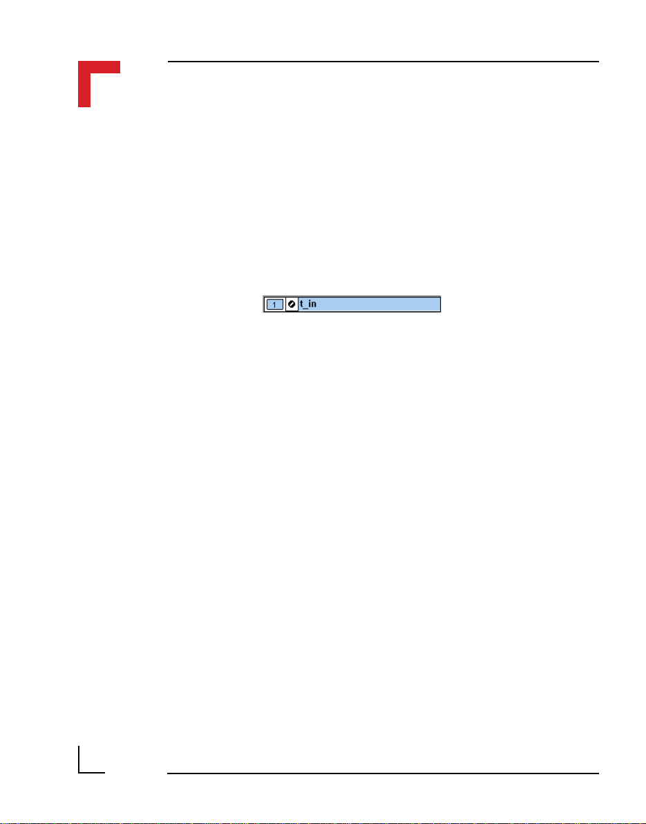
2.7 ISaGRAF Programming
2.7.1 The ISaGRAF Board Parameters
Information on board parameters may be found in the PEP online help and
ISaGRAF online help or user’s manual.
Figure 2.7.1.1 Typical Screen Section for the SMART-BASE
Because the communication to the timer/counter is performed using Operate
Calls, there is no need for manual selection of such things as a logical
address etc.
the operate call to decide which port to access.
t_in
represents a variable for the counter timer and is used for
Page 2 - 32
©1996 PEP Modular Computers GmbH
March 12, 1996

Chapter 2 SMART-BASE
2.7.2 The ISaGRAF Operate Calls
Operate calls are built into a program using ST or FBD languages when
defining the project. A typical use could be at the initialization stage to
check that the SMART-Modules are in fact located where they have been
programmed to be. The syntax of the operate call is as follows:
SMART I/O User’s Manual
Syntax:
<return variable> := OPERATE(<source var>, COMMAND,
<source data>);
Here the return variable is assigned a value associated with the
selected COMMAND parameter. A number of these COMMANDS exist for the
SMART-BASE.
Example:
<error.code>:= OPERATE(<channel>, O_INIT_CODE, 0);
O_INIT_CODE is one of a number of distinct commands recognized by the
PEP Modular Computers’ implementation of board drivers and checks for
example that a SMART-Module is located where the program expects it to
be.
channel provides channel specific information and in the example shown
here, any of the input channels may be used. The last parameter is not
usually used by PEP implementations and is set to 0 (zero).
The error.code returns a value of zero if no error was detected, otherwise it returns a non-zero value depending on the error encountered. A list of
these error codes may be found in the PEP online help.
2
©1996 PEP Modular Computers GmbHMarch 12, 1996 Page 2 - 33

SMART I/O User’s Manual
Chapter 2 SMART-BASE
A complete list of the operate COMMANDS may be obtained by selecting a
project from the ISaGRAF projects group, opening an application and
observing the Common defines in the Dictionary pull-down menu. Note that
not all calls in the list may be used within the SMART I/O environment
however, the calls applicable to this module are :
O_INIT_CODE : The syntax and usage have already been explained.
O_POWERFAIL_SET : The purpose of this operate call is to detect when
(if) the power to the PLC (SMART I/O) has failed.
The function is normally built into the initialization
stage of an application and has the following
syntax :
RetVar := OPERATE(s_time, O_POWERFAIL_SET, 0);
When the application is initialized, the start time is
recorded in battery backed ram (1) at the given
address (
s_time
). If the power to the PLC fails (2)
and recovers at a later stage (3), the software makes
a comparison with the actual clock time (via the
RTC) and the time stored in this memory location.
If a discrepancy exists then the RetVar will record
this fact. Refer to the PEP online help for more
information pertaining to the implementation of this
operate call.
Voltage
Page 2 - 34
123
Time
©1996 PEP Modular Computers GmbH
March 12, 1996

Chapter 2 SMART-BASE
O_START_COUNTER : This call starts the counter; it’s syntax is as follows :
<RetVar> := OPERATE(<iovar>, O_START_COUNTER, <null>);
SMART I/O User’s Manual
where the
O_READ_COUNTER : With this call the contents of the counter register
may be read. When this call is issued, the counter is
stopped, it’s register read and then restarted. If a
high-frequency input exists then pulses may be lost
(not counted). The same effect may also be true due
to timeslicing during timer stop and start operations.
Therefore it is recommended that this call be only
used for low frequency inputs (<1kHz). There is no
detection for counter overflow and the call should
not be used for count down operations or square
wave generation. It’s syntax is as follows :
<RetVar> := OPERATE(<iovar>, O_READ_COUNTER, <null>);
where the
O_STOP_COUNTER : This call stops the counter counting up or down and
square-wave generation and has the following
syntax :
<RetVar> := OPERATE(<iovar>, O_STOP_COUNTER, <null>);
where the
<iovar>
<iovar>
<iovar>
is typically t_in.
is typically t_in.
is typically t_in.
2
The counter/timer is configured automatically as MODE10 (refer to the ‘C’
Programming section) and from within ISaGRAF there is no ability to alter
this configuration.
©1996 PEP Modular Computers GmbHMarch 12, 1996 Page 2 - 35

SMART I/O User’s Manual
O_PRELOAD : With this call the counter preload register can be
set. The syntax is as follows :
<RetVar> := OPERATE(<iovar>, O_PRELOAD, <prevar>);
Chapter 2 SMART-BASE
where the
<prevar>
which lies between 1 and 0xFFFFFF.
O_START_CNTDWN : This function starts the counter counting-down.
When the counter reaches zero, it rolls over to the
maximum value of 0xFFFFFF on the following
clock pulse and starts afresh. The syntax is as
follows :
<RetVar> := OPERATE(<iovar>,O_START_CNTDWN,<prevar>);
where the
Timer I/O (typically t_in) and
one of
6 MHz/32 clock input or
t_in inputs.
<iovar>
is the value for the preload register
<iovar>
OA_PITCLOCK
is typically t_in and
is a variable attached to the
<prevar>
for selection of the
OA_TIN
for selection of
may be
Page 2 - 36
©1996 PEP Modular Computers GmbH
March 12, 1996

Chapter 2 SMART-BASE
2.8 Flash Utility
The flash utility allows ISaGRAF applications, a new ISaGRAF kernel or
other OS-9 modules to be loaded into FLASH memory. The SMART I/O
may be equipped with 1 MByte of memory depending on the version ordered. If an application is stored in FLASH then it will be loaded into the
system at start-up.
The main features of this utility are:
• Erase memory
• Fill memory
• Append memory
• Read memory
The following syntax should be observed:
flash -b[board] <parameter(s)>
SMART I/O User’s Manual
2
Examples
To erase the FLASH:
Isa: flash -b=SMART -p=ff
To write a file to FLASH (base address is $D00000):
flash -b=SMART -d=d00000 -i=path/filename
To append a file to existing FLASH contents:
flash -b=SMART -d=d00000 -u -i=path/filename
©1996 PEP Modular Computers GmbHMarch 12, 1996 Page 2 - 37

SMART I/O User’s Manual
Example to download ISA11 module and store in FLASH
Start the isa terminal in MS Windows:
Press the <ENTER> key three times to display the following screen prompt:
Isa:
Start kermit on the target system
Isa: kermit ri <ENTER>
Select the menu item transfers-send binary file from the windows terminal
and select the file flash on the PC to transfer
Load flash into memory
Isa: load -ld/dd/APL/flash
Chapter 2 SMART-BASE
Start kermit on the target system again
Isa: kermit ri <ENTER>
Select the menu item transfers-send binary file from the windows terminal
and select the file isa11 on the PC to transfer
Append the file to the existing flash contents
flash -b=SMART -d=d00000 -u -i=/dd/APL/isa11
Page 2 - 38
©1996 PEP Modular Computers GmbH
March 12, 1996

Chapter 3 SMART-EXT
3. SMART-EXT ...........................................3-3
3.1 Specifications ......................................................................... 3-3
3.2 Board Overview ..................................................................... 3-4
3.3 Functional Description........................................................... 3-5
3.4 Pinouts ................................................................................... 3-6
3.4.1 SMART Module Piggyback Connectors............................................. 3-7
3.4.2 Parallel I/O Screw Terminals (SCRA and SCRB) .............................. 3-8
3.4.3 SPI Connectors (ST5 and BU1) .......................................................... 3-9
SMART I/O User’s Manual
Table Of Contents
3
©1996 PEP Modular Computers GmbHMarch 12, 1996 Page 3 - 1

SMART I/O User’s Manual
This page has been left blank intentionally
Chapter 3 SMART-EXT
Page 3 - 2
©1996 PEP Modular Computers GmbH
March 12, 1996

Chapter 3 SMART-EXT
3. SMART-EXT
The SMART-EXT is a carrier unit enabling the connection of a further 2
SMART-Modules thereby enhancing the I/O capacity of the SMART I/O
system. Up to 4 of these extensions may be cascaded via a 10-wire flat-band
cable with integrated 3-wire SPI (Serial Peripheral Interface). To achieve a
common interface between modules, a SMART I/O ‘C’ library is provided by
PEP.
3.1 Specifications
SMART I/O User’s Manual
Controller
- Frequency
- Firmware
Interface Speed Set to 1 MHz
Power Consumption Typ. 25 mW
Temperature Range
- Storage
- Standard
- Extended
Operating Humidity 0 to 95% non-condensing
Weight
The SPI follows a Motorola defined communication protocol which is
beyond the scope of this manual to describe. More information may be found
by referring to the relevant data-sheets.
MC68HC705C8A
4 MHz
PEP Firmware for OTP device
-20°C to + 125°C
0°C to +70°C
-40°C to +85°C
260g (without modules, blank
panels or screw terminals
3
©1996 PEP Modular Computers GmbHMarch 12, 1996 Page 3 - 3
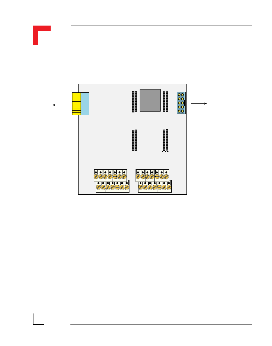
SMART I/O User’s Manual
3.2 Board Overview
From SMART-BASE
or other SMART-EXT
Modules
SPI
BU1
ST3 ST1
MCU
68HC05C4
ST4 ST2
SMART Modules
I/O Slot BI/O Slot A
Chapter 3 SMART-EXT
SPI
ST5
To further SMART-EXT
Modules
Page 3 - 4
SCRA SCRB
©1996 PEP Modular Computers GmbH
March 12, 1996

Chapter 3 SMART-EXT
3.3 Functional Description
Figure 3.3.1: SMART-EXT Block Diagram
SMART I/O User’s Manual
Interface
Connector
with
Integrated
SPI
Slot Detect
Logic and
Slot
A
Buffer
Slot
B
Interface
Connector
with
Integrated
SPI
The SMART-EXT is a carrier board for up to 2 SMART-Modules with data
transfer between SMART-BASE and EXT units being performed by the
interface connector incorporating the Motorola synchronous Serial Peripheral
Interface (SPI).
The maximum bit transfer rate is set to 1 MHz which ensures a typical
response time from an addressed extension slot of approximately 50µs.
The MCU (Micro Controller Unit - 68HC05C4) handles the SPI transfers
and the slot-dependent commands and actions through the SMART-EXT
firmware burned into the MCU mask or in an OTP (One-Time Programmable) PROM area.
In order to communicate with a particular SMART-EXT slot, a specific PEP
defined protocol has to be observed. All necessary functions are provided in
the OS-9 ‘C’ library SMAC.L which should be included when writing a
specific C’ application program.
3
©1996 PEP Modular Computers GmbHMarch 12, 1996 Page 3 - 5
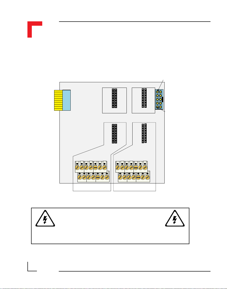
SMART I/O User’s Manual
3.4 Pinouts
Figure 3.4.0.1: SMART-EXT Pinout Overview
Chapter 3 SMART-EXT
SPI
Pin 1
Pin 9
Pin 2
BU1
Pin 10
Pin 15Pin 16
ST1
Pin 1Pin 2
Slot A
Process SIde
Pin 15Pin 16
ST2
Pin 1Pin 2
Slot A Slot B
Pin 1
Pin 2
Slot #3,5,7,9 Slot #4,6,8,10
Pin 13
Pin 14
Pin 1
Pin 2
SCRA SCRB
WARNING !
ST3
Digital Side
ST4
Slot B
Pin 13
Pin 15Pin 16
Pin 1Pin 2
Pin 15Pin 16
Pin 1Pin 2
Pin 14
SPI
Pin 1
Pin 2
ST5
Pin 10
Pin 9
Page 3 - 6
Dangerous voltages may be present at the terminals.
©1996 PEP Modular Computers GmbH
March 12, 1996
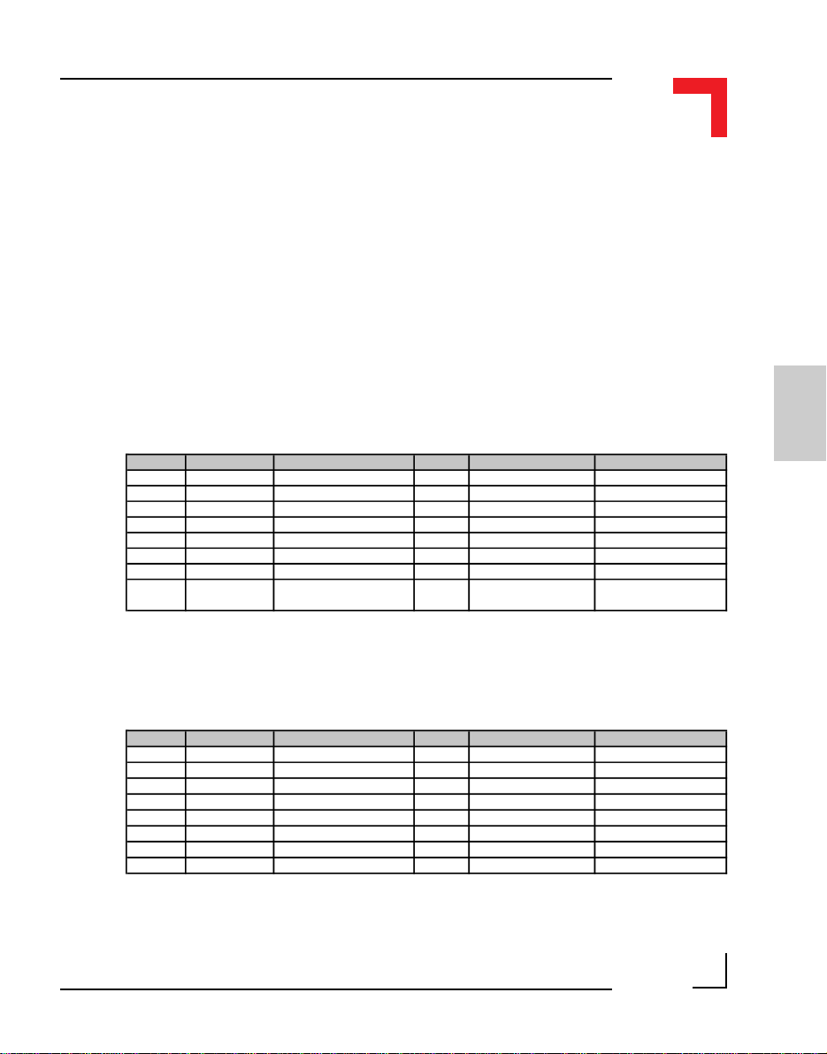
Chapter 3 SMART-EXT
3.4.1 SMART Module Piggyback Connectors
There are two sets (one for each module) of SMART-Module piggyback
connectors present on the SMART-EXT, each divided into two sets of 2x8
standard pin rows. The communication to these connectors is achieved in
part via the 10-wire flat-band interface cable and directly by the MCU.
Pinouts digital side (ST1 and ST3)
Refer to figure 3.4.0.1 for the correct location of these pin-row connectors.
SMART I/O User’s Manual
Slot A from 68HC05C4 MCU port A (ST1)
Pin Nr. Signal Description Pin Nr. Signal Description
1 PA1 Port A Pin 1 2 PA2 Port A Pin 2
3 PA3 Port A Pin 3 4 PA4 Port A Pin 4
5 PA5 Port A Pin 5 6 PA6 Port A Pin 6
7 PA7 Port A Pin 7 8 PA8 Port A Pin 8
9 System GND GND 10 Serial RxD RxD to SM-BASE
11 System VCC System +5V VCC 12 Serial TxD TxD from SM-BASE
13 CS-SLOTA Chip Select A 14 Serial CLK CLK from SM-BASE
15 Reset Power ON/OFF Reset 16 Slot A Interrupt line
INT4 to the
I/O Controller
Slot B from 68HC05C4 MCU port B (ST3)
Pin Nr. Signal Description Pin Nr. Signal Description
1 PB1 Port B Pin 1 2 PB2 Port B Pin 2
3 PB3 Port B Pin 3 4 PB4 Port B Pin 4
5 PB5 Port B Pin 5 6 PB6 Port B Pin 6
7 PB7 Port B Pin 7 8 PB8 Port B Pin 8
9 System GND GND 10 Serial RxD RxD from SM-BASE
11 System VCC System +5V VCC 12 Serial TxD TxD from SM-BASE
13 CS-SLOTB Chip Select B 14 Serial CLK CLK from SM-BASE
15 Reset Power ON/OFF Reset 16 Slot B Interrupt line Interrupt PI/T (H4)
3
©1996 PEP Modular Computers GmbHMarch 12, 1996 Page 3 - 7
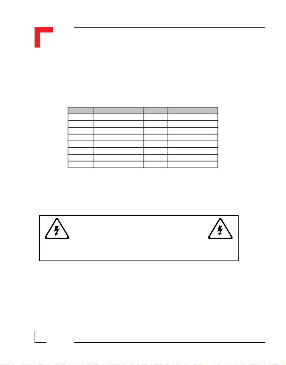
SMART I/O User’s Manual
Pinouts process side (ST2 and ST4)
Refer to figure 3.4.0.1 for the correct location of these pin-row connectors.
Slots A and B (ST2 and ST4)
Pin Nr. Signal Pin Nr. Signal
1 Screw Terminal 13 2 Screw Terminal 13
3 Screw Terminal 1 4 Screw Terminal 2
5 Screw Terminal 3 6 Screw Terminal 4
7 Screw Terminal 5 8 Screw Terminal 6
9 Screw Terminal 7 10 Screw Terminal 8
11 Screw Terminal 9 12 Screw Terminal 10
13 Screw Terminal 11 14 Screw Terminal 12
15 Screw Terminal 14 16 Screw Terminal 14
The PC board connections to the screw terminals are capable of absorbing a
continuous current of up to 3A each. However, pins 13 and 14 can support up
to 6 Amps.
Chapter 3 SMART-EXT
WARNING !
Dangerous voltages may be present at the terminals.
3.4.2 Parallel I/O Screw Terminals (SCRA and SCRB)
The screw terminal blocks are individually composed of 7 free connections
which, when stacked provide 14 free connections per I/O slot. The pinout
functionality depends on the type of SMART-Modules fitted and the relevant
module should be referred to in the appropriate section of this manual.
Page 3 - 8
©1996 PEP Modular Computers GmbH
March 12, 1996
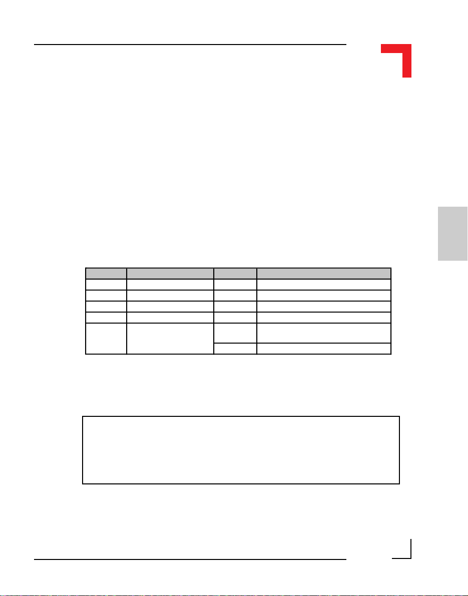
Chapter 3 SMART-EXT
3.4.3 SPI Connectors (ST5 and BU1)
On both sides of the board are standard 2x5 pinrow connectors (BU1, ST5),
that provide the interface connection between SMART-EXT units and the
SMART-BASE.
A 10-wire flat cable is soldered directly on the left-hand side of the board
(BU1), that interfaces the SMART-BASE module or other (earlier cascaded)
SMART-EXT modules.
SMART I/O User’s Manual
Pinouts for this 10-pin connector
Pin Nr. Signal Pin Nr. Signal
1 System VCC (+5V) 2 Serial RxD from SMART-BASE
3 System VCC (+5V) 4 Serial TxD from SMART-BASE
5 Serial Ext. Select 6 Serial CLK from SMART-BASE
7 System GND 8 Reset (Power ON/OFF)
9 System GND 10 (BU1)
10 (ST5) N/C
Pin 10 of BU1 is only useful on the first SMART-EXT connected to the
SMART-BASE. For this reason, SMART-Modules utilizing this feature
can only be connected to the first slot of the first extension unit.
Serial Ext. Interrupt
(INT4 1st Module only)
Note
3
©1996 PEP Modular Computers GmbHMarch 12, 1996 Page 3 - 9

SMART I/O User’s Manual
This page has been left blank intentionally.
Chapter 3 SMART-EXT
Page 3 - 10
©1996 PEP Modular Computers GmbH
March 12, 1996

Digital Modules
Digital Modules
SMART I/O User’s Manual
08 Jan. 98
Page 4 - 1Manual ID 09901, Rev. Index 0500

SMART I/O User’s Manual
Table of Contents
Digital Modules
Chapter
4
4.1 SM-DIN1............ ................. .. ................. ... 4-5
4.1.1Introduction .................................................. 4-5
4.1.2Specifications .............................................. 4-5
4.1.3Front Panel Layout ...................................... 4-6
4.1.4Board Overview ........................................... 4-7
4.1.5Functional Description ................................. 4-8
4.1.6 Configuration ............................................... 4-9
4.1.7Pinouts ...................................................... 4-10
4.1.8‘C’ Programming .............................. ..... ..... 4-12
4.1.9ISaGRAF Programming ............................. 4-16
4.2 SM-DOUT1......................... ................. ... 4 -1 9
4.2.1Introduction ................................................ 4-19
4.2.2Specifications ............................................ 4-19
4.2.3Front Panel Layout .................................... 4-20
4.2.4Board Overview ......................................... 4-20
4.2.5Functional Description ............................... 4-21
4.2.6 Configuration ............................................. 4-22
Page 4 - 2
08 Jan. 98Manual ID 09901, Rev. Index 0500

Digital Modules
SMART I/O User’s Manual
4.2.7 Pinouts ...................................................... 4-22
4.2.9ISaGRAF Programming ............................ 4-29
4.3 SM-REL1................................................ 4-33
4.3.1Introduction ............................................... 4-33
4.3.2 Specifications ............................................ 4-33
4.3.3Front Panel Layout ................................ .... 4-34
4.3.4Board Overview ........................................ 4-34
4.3.5Functional Description .............................. 4-35
4.3.6Configuration ............................................. 4-36
4.3.7 Pinouts ...................................................... 4-36
4.3.8‘C’ Programming ....................................... 4-38
4.4 SM-ACI1................................................. 4-53
4.4.1Introduction................................................ 4-53
4.4.2 Specifications ............................................ 4-54
4.4.3Front Panel Layout ................................ .... 4-55
4.4.4Board Overview ........................................ 4-56
4.4.5Functional Description .............................. 4-58
4.4.6Configuration ............................................. 4-59
4.4.7Screw Terminal Pinouts ............................ 4-61
4.4.8‘C’ Programming ....................................... 4-64
4.4.9ISaGraf Programming................................ 4-68
08 Jan. 98
Page 4 - 3Manual ID 09901, Rev. Index 0500

This page was intentionally left blank.

Chapter 4 Digital Modules
4. Digital Modules
4.1 SM-DIN1
4.1.1 Introduction
The SM-DIN1 provides 8 optoisolated 24V DC digital inputs arranged in 6
independent groups with respect to the ground connections. The maximum
input switching frequency is set to 200Hz with the system registering a
logical ‘1’ when the input exceeds 10V. Logical ‘0’ is returned when the
input falls below 8V. A low-pass filter restricts signals exceeding the filter
limit and registers a logical ‘0’ with the system. The user interface is realized
by 8 green LEDs (one per input channel) which illuminate when the input
exceeds 10V DC and a configurable filter on the last channel for INTx
interrupts (where ‘x’ lies between 1 and 4 depending on which slot the
module is located).
4.1.2 Specifications
SMART I/O User’s Manual
4
Isolation 2.5 kV optoisolated from the system
Input
Front Panel Green LEDs (ON when Input > 10V)
Options User configurable R-C filter on the
Power Consumption 5mW (min.), 100mW (max.)
Temperature Range Standard (0°C to +70°C), Extended (-40°C to +85°C)
Module Weight 40g
ID Byte $01, read by the SPI Interface
8 Digital Channels (24V) DC ± 10%
6 Independent Groups
Common GND
< 5mA Input Current
Filter set to 200 Hz (5ms)
Overvoltage Protection (rate)
Overvoltage Protection (continuous)
Switch ON Delay
Switch OFF Delay
High Level
Low Level
last channel for INTx generation
©1996 PEP Modular Computers GmbHMarch 12, 1996 Page 4 - 5
: 300V/90µs
: 35V
: 2ms (approx.)
: 2ms (approx.)
: > 10V
: < 8V

SMART I/O User’s Manual
4.1.3 Front Panel Layout
Green LEDs
Chapter 4 Digital Modules
User Descriptor
Fields
Page 4 - 6
©1996 PEP Modular Computers GmbH
March 12, 1996

Chapter 4 Digital Modules
4.1.4 Board Overview
Component Side
Input
Circuit
Optoisolation
Low
Pass
Filter
SMART I/O User’s Manual
LED 0LED 7
ID
Register
Digital Input
and LED Drivers
Solder Side
Pin 1
Pin 2
LED 0
Pin 16
Pin 15
BU1 BU2
Pin 16
J2
BU2
Pin 2
Pin 1
Pin 2
LED 7
2
1
3
2
J1
1
3
Pin 16 Pin 2
Pin 15
Pin 16
BU1
©1996 PEP Modular Computers GmbHMarch 12, 1996 Page 4 - 7
4
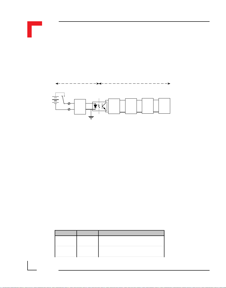
SMART I/O User’s Manual
4.1.5 Functional Description
Figure 4.1.5.1: SM-DIN1 Schematic Diagram
Chapter 4 Digital Modules
+Vcc (24V)
Gnd (common)
User/Input
Interface
Input
Circuit
Low
Pass
Filter
System
Interface
Digital
Input
LED
Driver
System
Interface
The input circuit comprises a Zener diode requiring 3mA to drive it beyond
the ‘knee’ that borders between ‘OFF’ and ‘ON’. More simply, input
voltages between 8V and 10V DC produce an unknown digital result.
After the optoisolation part of the circuit, an R-C first-order, low-pass filter
prevents noise and signals greater than 200Hz from entering the system
digital input. This filter is factory set on all channels but may be altered to a
value according to customer specifications.
The LED driver activates the relevant LED when the input exceeds 10V DC.
As previously mentioned, the last channel is capable of issuing IRQx interrupts when enabled by software. This interrupt will only be acknowledged
under OS-9 if the module is on the SMART-BASE or occupies the first slot
of the first attached SMART-EXT unit. This channel is factory set at 200Hz
but higher frequencies may be catered for. The table below shows the solderjumper settings for this filter configuration.
Page 4 - 8
Jumper Settings Description
J1
1-2 Standard input filter 200Hz
1-3 Customer specific input filter
J2
1-2 Standard input filter 200Hz
1-3 Customer specific input filter
©1996 PEP Modular Computers GmbH
March 12, 1996
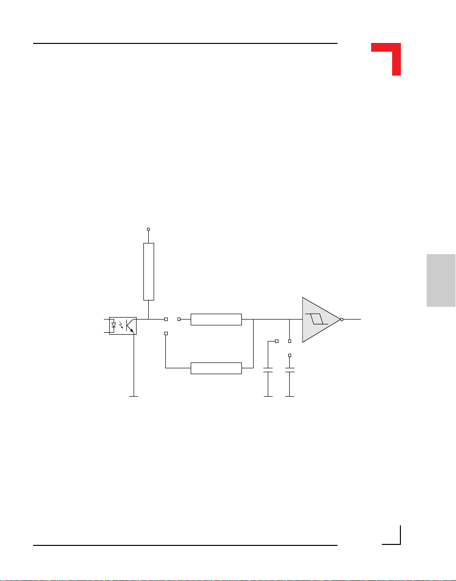
Chapter 4 Digital Modules
4.1.6 Configuration
Although two solder jumpers exist on the board (J1 and J2), they should
remain at their factory settings unless a user-specific filter is required that
cuts off at higher frequencies for example. If a user-specific filter is required
then contact PEP Modular Computers for further advice and refer to the
illustration shown in figure 4.1.6.1 of the filtering components.
Figure 4.1.6.1: SM-DIN1 Configurable Filter
Vcc
36k
SMART I/O User’s Manual
IC10
4
12
J1
3
36k
*
R1
3
1
J2
2
*
C13 100nF
INTx
HCT14
Surface Mounted Devices (SMD) are used in the production of the SMDIN1 modules. The components to be changed (marked with an asterisk in
figure 4.1.6.1), need not necessarily be SMD. Refer to the Board Overview
(solder side) for the approximate position of these jumpers. It should be
noted that when calculating component values for a specific filter, the
capacitor/resistor relationship is almost linear. Therefore, it is suggested that
only the capacitor should be changed. Hence, for a doubling of filter frequency input the value of the capacitor should be reduced by half.
©1996 PEP Modular Computers GmbHMarch 12, 1996 Page 4 - 9
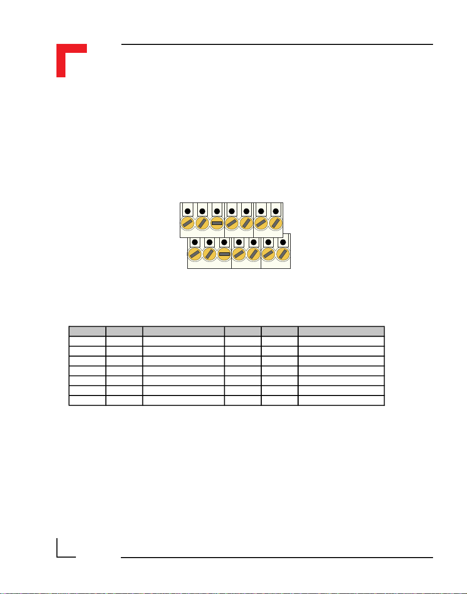
SMART I/O User’s Manual
Chapter 4 Digital Modules
4.1.7 Pinouts
Screw Terminal Pinouts
The following shows the pinout/signal relationship for the SM-DIN1 when
connected to a particular screw terminal block.
Pin 1
Pin 2
Pin Nr. Signal Description Pin Nr. Signal Description
1 G0EXT GND for channel 0 2 G4EXT GND for channel 4
3 IN0 Input Channel 0 4 IN4 Input Channel 4
5 IN1 Input Channel 1 6 IN5 Input Channel 5
7 G1EXT GND for channel 1 8 G5EXT GND for channel 5
9 IN2 Input Channel 2 10 IN6 Input Channel 6
11 IN3 Input Channel 3 12 IN7 Input Channel 7
13 G23EXT GND for channels 2&3 14 G67EXT GND for channels 6&7
Pin 13
Pin 14
Page 4 - 10
©1996 PEP Modular Computers GmbH
March 12, 1996
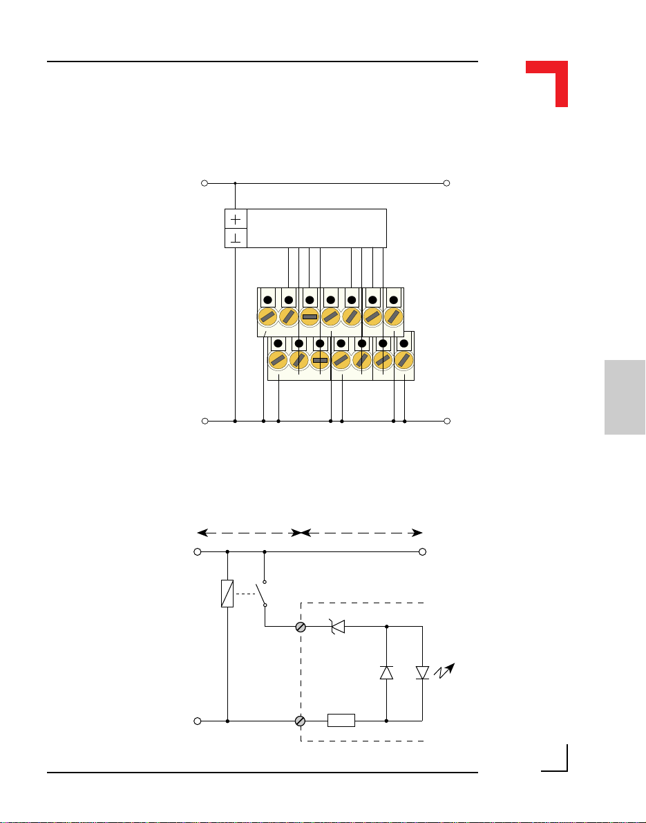
Chapter 4 Digital Modules
Connection
Digital Sensors
IN0
Pin 1
SMART I/O User’s Manual
+Vcc (24V)
IN3
IN6
IN2
IN5
IN1
IN4
IN7
Pin 13
Input Circuit
+Vcc (24V)
Gnd (0V)
K1
Pin 2
User/Input
Interface
G0EXT
G4EXT
IN0
G0EXT
G1EXT
G5EXT
System Interface
8V2
LL4448
5K1
G23EXT
G67EXT
Pin 14
4
Gnd (0V)
Typ: Common GND
©1996 PEP Modular Computers GmbHMarch 12, 1996 Page 4 - 11

SMART I/O User’s Manual
4.1.8 ‘C’ Programming
4.1.8.1 SM-DIN1 Library
The SM-DIN1 library of functions smartio.l provide a convenient way of
accessing the SM-DIN1 module.
• All functions are written in ANSI C;
• Prototypes are to be found in the file din1lib.h.
Hardware Requirements
• SMART I/O Base Module or Base Module and Extension unit;
• SM-DIN1 Module.
Software Requirements
Chapter 4 Digital Modules
The compiler from one of the following:
• Ultra C Version 1.1.2 or higher;
• FasTrak 2.0.2 or higher.
The leftmost SM-Module has number 0 assigned to it a far as programming
is concerned although physically this is slot 1!
Before a library function can be used, the function SMDIN1Init must first be
called. This allocates the requested resources. Furthermore, this function
needs to be called for each SM-DIN1 Module called within the task. Upon
completion of the application, the function SMDIN1DeInit needs to be called
for each SM-DIN1 Module that has been initialized.
In order to illustrate the use of the SM-DIN1 library, an application example
called demodin1.c can be found in the SMART I/O application directory
(normally found in /<device>/APPLIC/SMART/CMDS).
Page 4 - 12
©1996 PEP Modular Computers GmbH
March 12, 1996
 Loading...