

Page 1
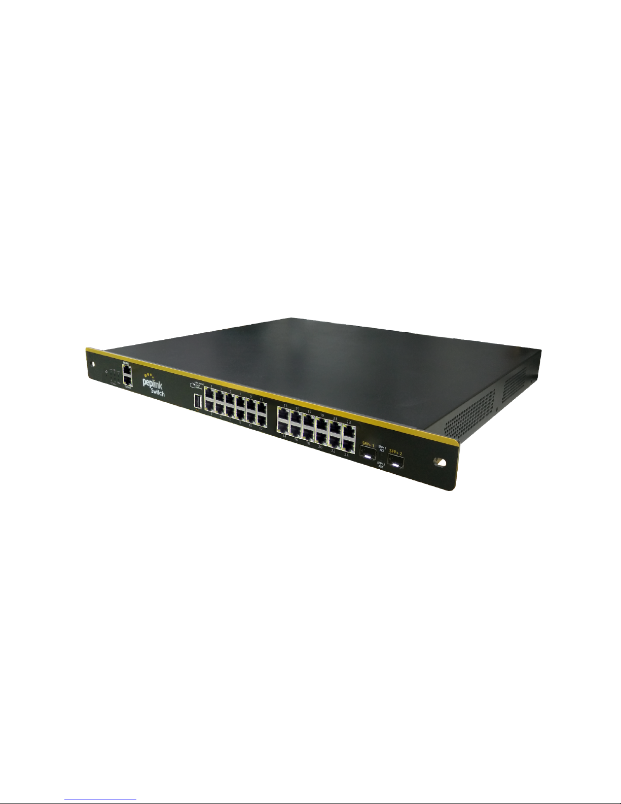
Peplink SD Switch User Manual
Published on October 25th, 2018
Page 2

Table of Contents
Switch Layout 3
Specifications 4
Hardware Overview 5
Quick Start Functions 6
Reset switch 6
Connect Ethernet 6
Connect SFP+ 6
Connect to Management Port 6
Connect to Console Port 7
InControl Configuration 7
Add switch to InControl 7
Enable InControl Cloud Management 9
Configuring VLANs 10
Define a new VLAN 12
Default VLAN settings 13
InControl Device Details 14
Port List 16
Port details and configuration 18
Port List 19
LACP - Link Aggregation 21
InControl Reports 22
InControl Clients 22
InControl Settings 23
Settings > Remote Web Admin 23
Settings > Firmware Management 23
Stand Alone Configuration 24
Standalone menu options > Dashboard 25
Standalone menu options > Configure > Network Settings 27
Standalone menu options > Configure > Interfaces > Switch Ports 28
LACP (802.3ad) configuration 30
Standalone menu options > System > Admin Security 31
Standalone menu options > System > Firmware 33
Page 3

Standalone menu options > System > Time 34
Standalone menu options > System > Schedule 34
Establish a Scheduling Profile 34
Standalone menu options > System > Email Notification 36
Standalone menu options > System > Event Log 37
Standalone menu options > System > SNMP 37
Standalone menu options > System > InControl 39
Standalone menu options > System > Configuration 40
Standalone menu options > System > Reboot 41
Standalone menu options > System > Tools 41
Ping 42
Traceroute 42
Wake-on-LAN 43
Standalone menu options > Status > Device 43
Standalone menu options > Status > Client List 44
Standalone menu options > Status > Event Log 45
Page 4
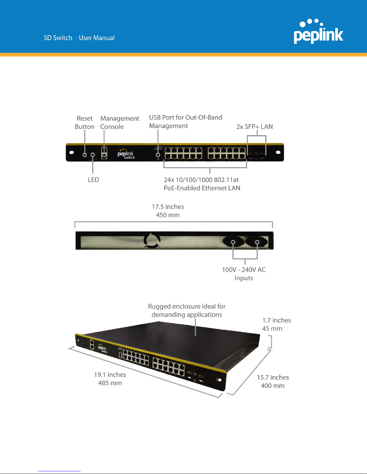
Switch Layout
Page 5
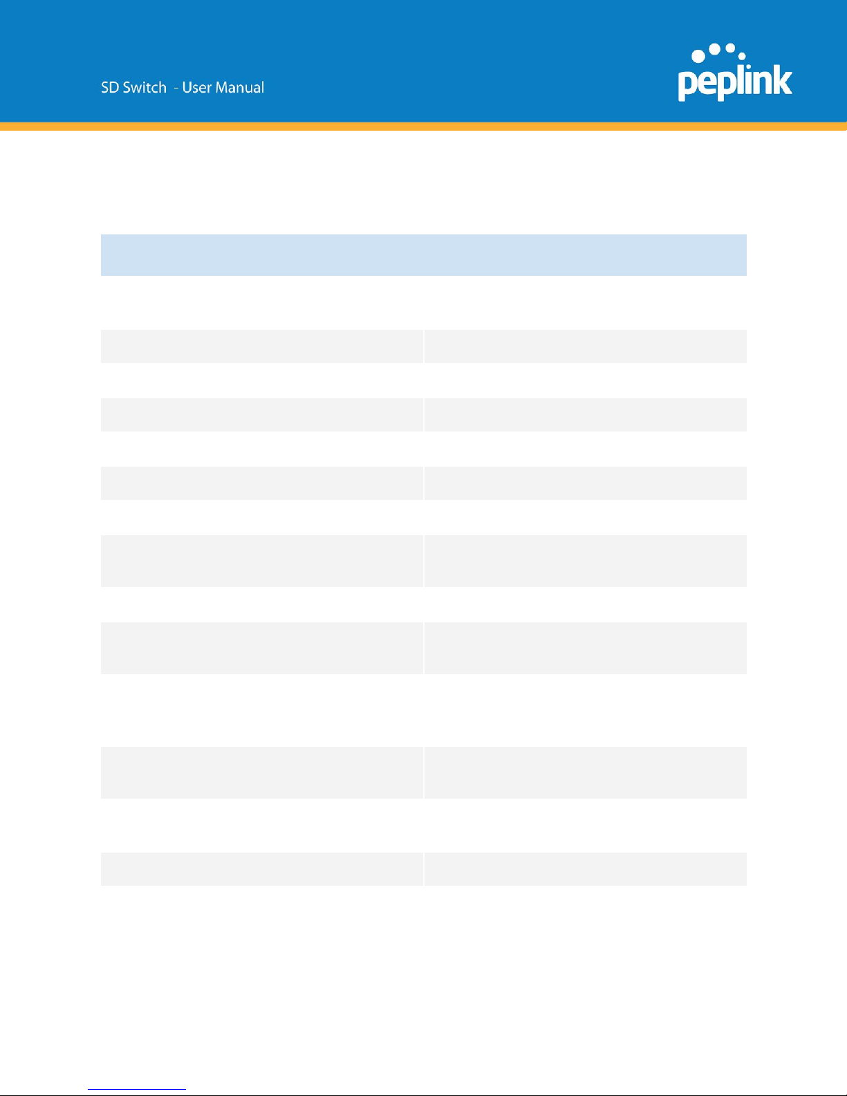
Specifications
SD Switch
LAN Interface
24x 10/100/1000 802.3at (PoE+) enabled
GbE ports, 2 x SFP+ ports
Switching Capacity
88 Gbps
Max. Packet Forwarding rate
66 Mbps
MAC Address Table Size
24K
VLAN Groups
Yes
Fiber Module
10 Gbps
Power Input
2 or 3x 100V - 240V AC Input (depending on
model) , with power redundancy
Power source
2 or 3x PSU
Power Consumption
50W System, 550W or 850W P0E+
PowerBudget
Dimensions
19.1 x 15.7 x 1.7 inches
485 x 400 x 45 mm
(L x W x H)
Weight
17.6 pounds
8.0 kg
Operating Temperature
32° - 104° F
0° - 40° C
Humidity
15% - 95% (non-condensing)
Warranty
1-Year limited Warranty
Page 6
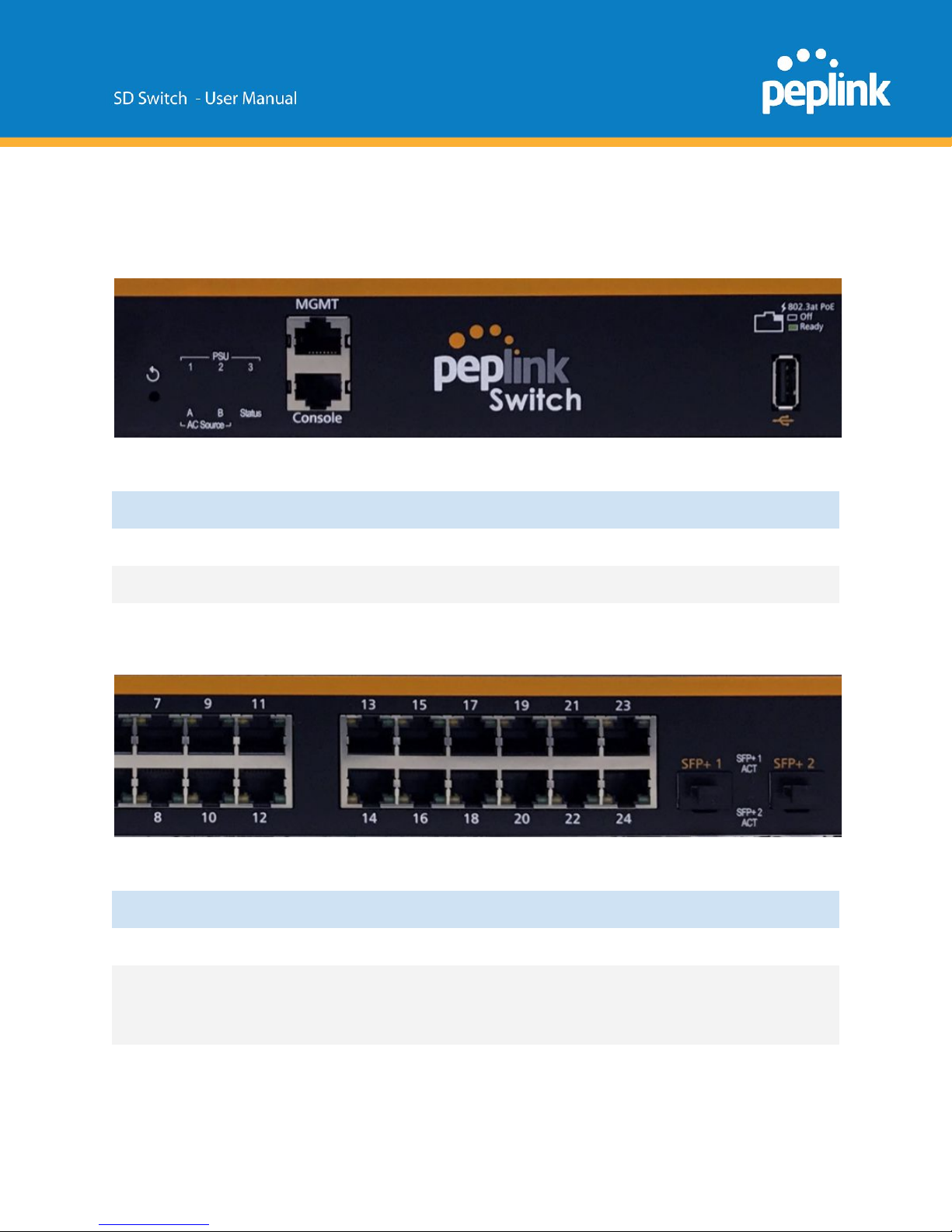
Hardware Overview
Front Panel Port LED
Port
LED
State
Status
PSU
No PoE
MGMT
IEEE 802.3a?
Port
LED
State
Status
Console
RJ45 1-24
poe /speed/link/act
off/green/orange
Link established
(flashing indicates
network activity)
SFP+ 1-2
Page 7

Quick Start Functions
Reset Switch
With a paperclip, press and hold the reset button for at least 10+ seconds, until all the lights light
up.
(If you press and hold the reset button for only 5-10 seconds, instead of a factory reset, the
admin user password will be reset to ‘admin’ and access will be reset to HTTP)
Connect Ethernet
Connect an RJ45 cable from an Internet-enabled router to any RJ45 port on the Peplink SD
Switch.
Connect an RJ45 cable from any client device to port 1-24 of the Peplink SD Switch.
Connect SFP+
Remove the protective plastic cover from the SFP+ port.
Plug a compatible fiber module into the SFP port.
Compatible SFP+ modules are: QUESTION!
Connect to Management Port
The management port is designed for Out-of-Band management.
The SD-Switch can be managed via this port only by default.
The management Port IP address is 192.168.1.254/24
Connect a RJ45 to the management port and a client device.
Configure the client device with an IP address in the 192.168.1.0/24 range.
Open a web browser and enter the default IP address of the management port in the address
field of the web browser ( http:\\192.168.1.254) to access the web interface of the Peplink
Switch.
Page 8
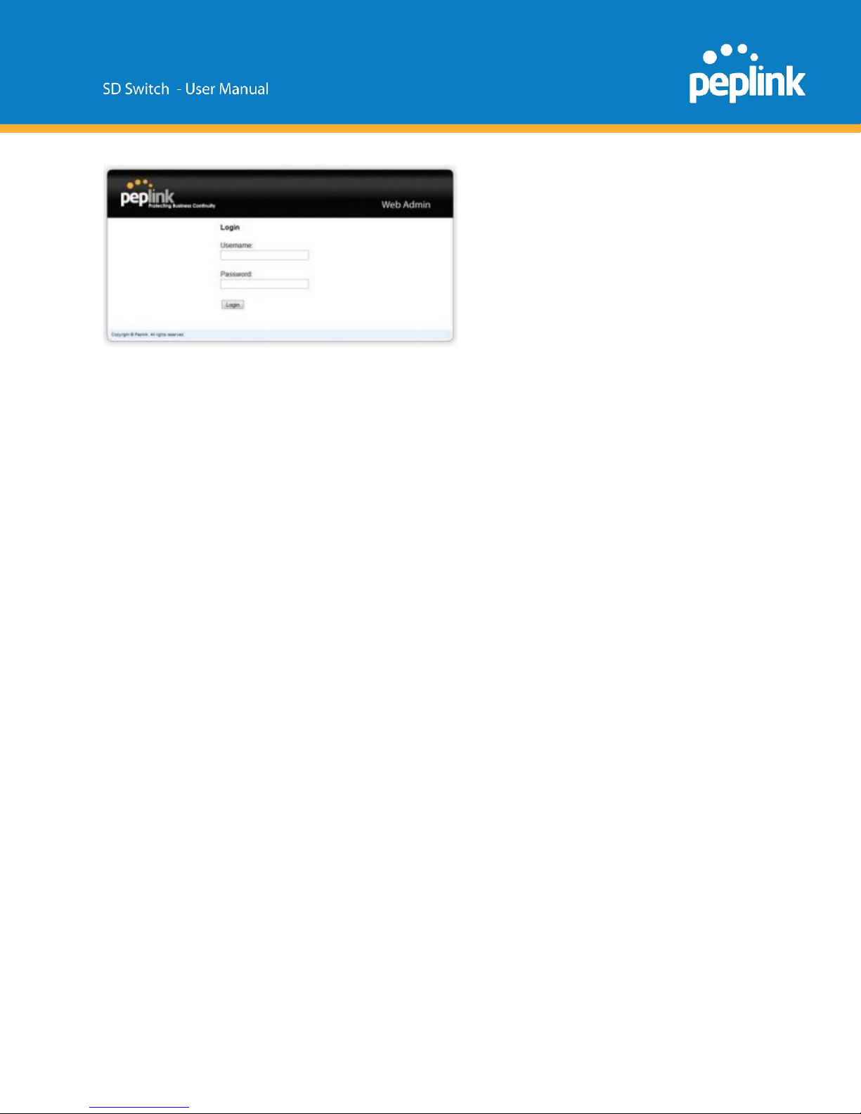
Login with the default credentials:
Username: admin
Password: admin
(This is the default admin user login of the Peplink Balance. The admin and read-only user
password can be changed at System>Admin Security.)
Connect to Console Port
Access the SD-Switch via this port with CLI to get the status and info of the switch.
This is currently under development.
InControl 2 Configuration
There are two ways to configure the Peplink Switch.
Through InControl 2, Peplink’s cloud-based device management and monitoring application, or
through the web admin interface.
This section describes an overview of the InControl 2 settings and information specific to the
Peplink Switch.
For a complete overview of InControl 2 options, please refer to our InControl 2 documentation.
Add Switch to InControl 2
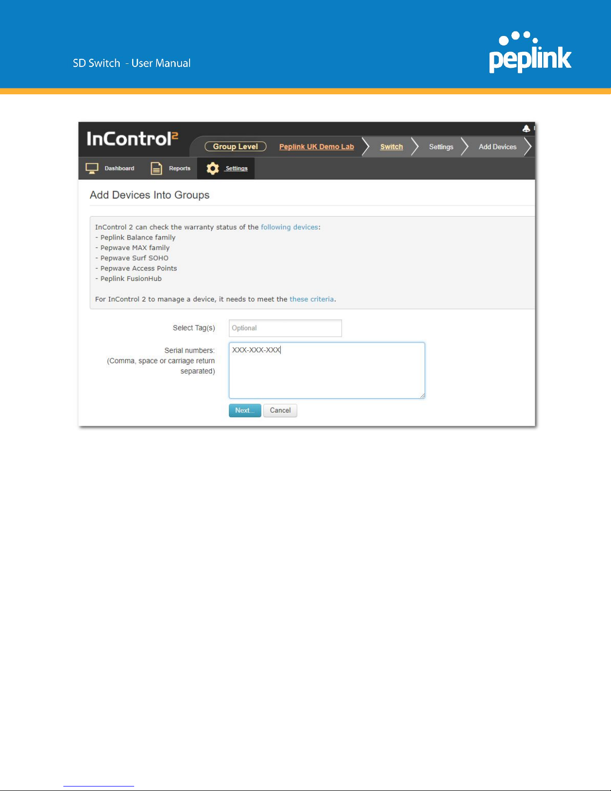
1: Logon to InControl 2 and create a separate group for your Peplink switch.
Add the switch serial number and follow the onscreen instructions.
Page 9
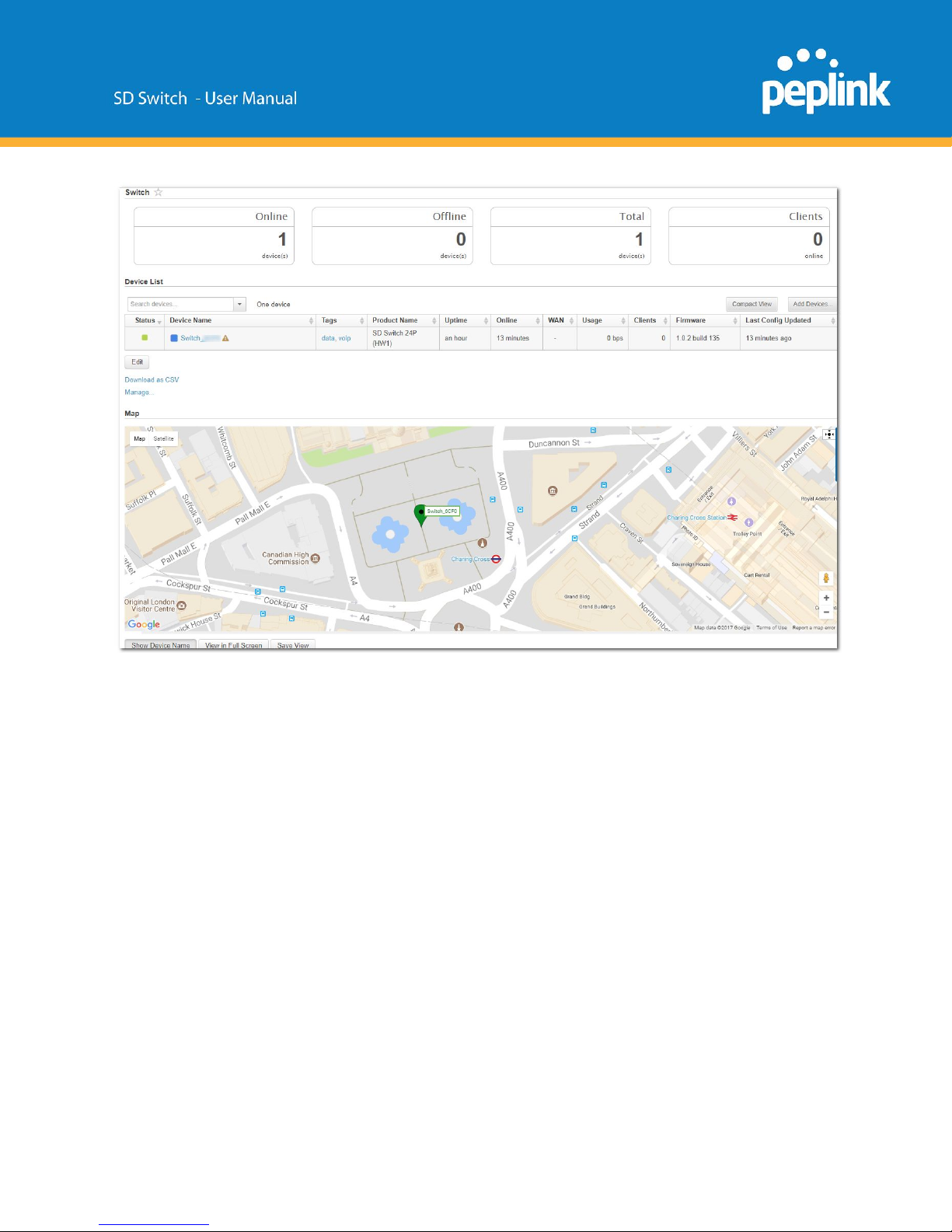
2: Connect an active ethernet connection to one of the numbered switch ports 1 to 24.
3: The Switch will show online in InControl 2 (the marker on the map will change from red to
green).
Page 10
Enable InControl 2 Cloud Management
InControl 2 management needs to be enabled to allow the Peplink Switch to be configured
through InControl 2.
This setting is enabled by default.
The settings can be changed in the local web interface of the Switch.
In Incontrol 2, browse to the Device Details page.
Select: Settings > Remote Web Admin to connect to the Switch local web interface.
Page 11
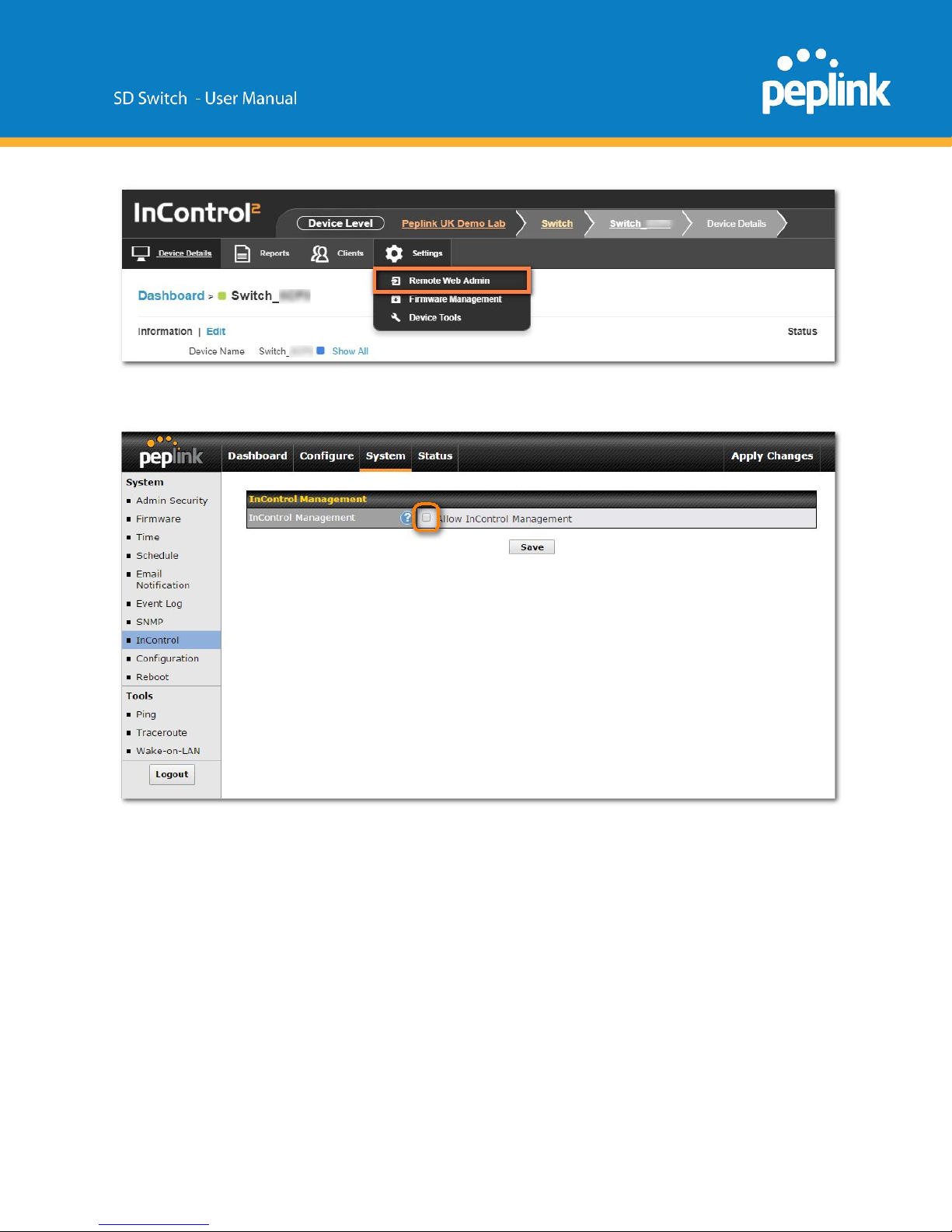
Navigate to System > InControl, and then click the “Allow InControl Management” button
Click the “Apply Changes” text on the top-right corner to save your changes.
Configuring VLANs
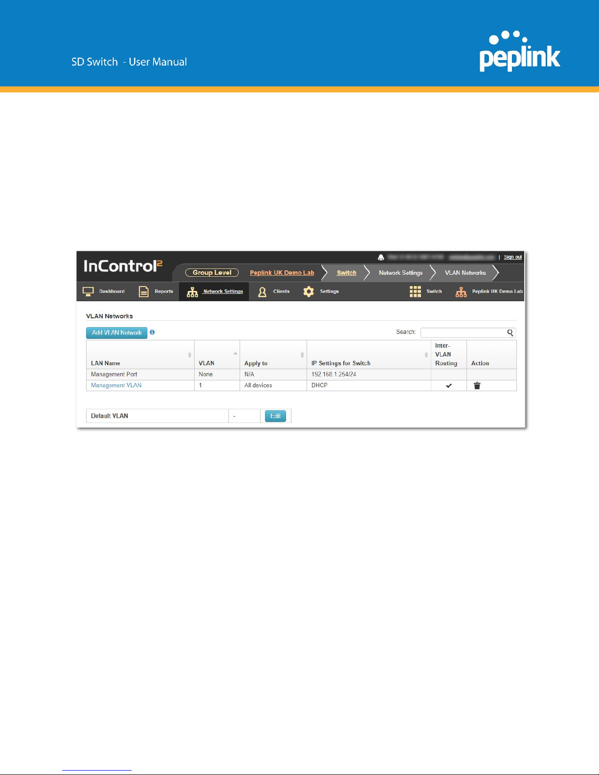
From the available InControl Group settings, the Network Settings > VLAN Networks has
several Switch-specific settings and behaviors.
VLANs defined on a device but not on InControl are "device managed", which means that
InControl will not manage them.
VLANs defined on both a device and InControl are "InControl managed", which means that:
InControl will control their Name and Captive Portal settings.
Page 12
Their IP and DHCP settings will be kept intact.
When a VLAN is removed from InControl, it will be removed from the device as well.
If a VLAN gets defined on InControl, but not yet on the device, it will be defined on the device as
well.
Its IP address will follow the Default IP Address setting. DHCP server will be enabled with
default settings.
When a Switch is added to a group in InControl, a Management Port and Management VLAN
are imported from the local Switch to InControl.
Important: The Peplink switch is a Layer 2 switch. Any routing options that are shown in the
VLAN settings (like Inter-VLAN routing) do NOT apply to the switch. These settings are only
applied to Peplink Balance and Pepwave Max routers in the same InControl group supporting
that option.
By default, this VLAN is applied on any device that is added to this group.
Each VLAN can be applied to a selection of devices in the group by using tags.
Tags can be configured in the device details.
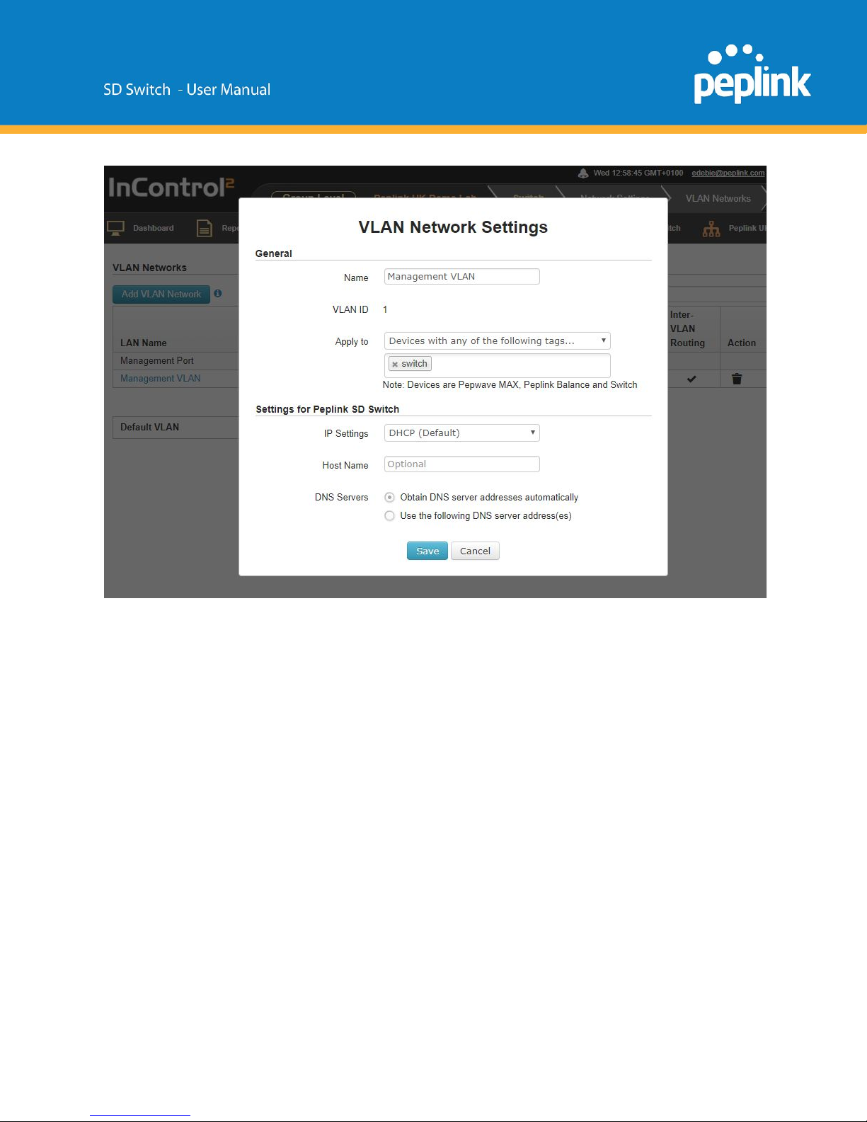
Detailed management VLAN network settings:
Page 13
Define a new VLAN
To add a new VLAN click on the “Add VLAN Network” button in the Network settings > VLAN
Networks section of InControl.
Page 14
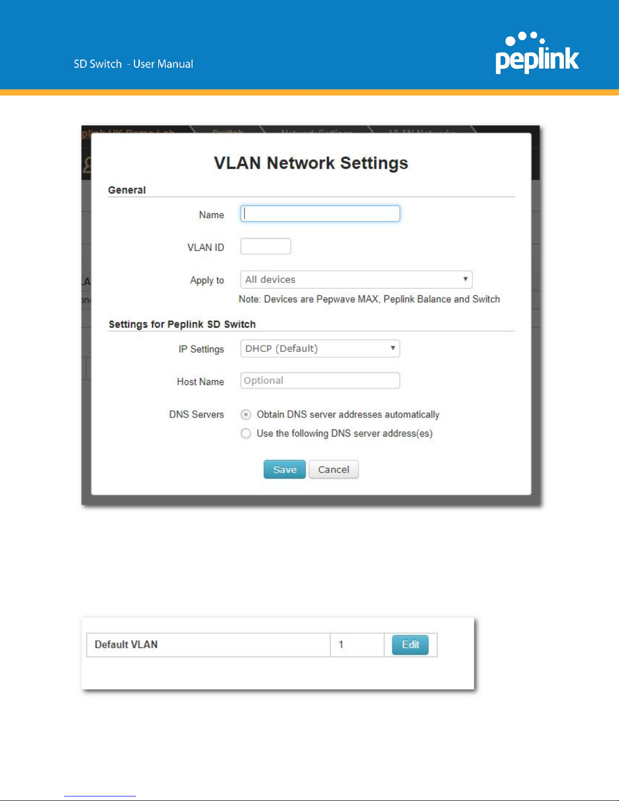
Enter the desired parameters and click “Save” to apply the settings.
Default VLAN Settings
Page 15

This setting is only applicable to all Peplink SD Switches' trunk ports which are configured with the
“Accept Frame Type” option set to "All".
When any untagged frames or frames tagged as this VLAN enter into those trunk ports, they will be
assigned to this VLAN. Any frames on this VLAN leaving from those trunk ports will be untagged.
By default, the default VLAN ID is set to 1.
When any untagged frames or frames tagged as 1 enter into any Peplink SD Switch's trunk ports which
are configured with Accept Frame Type option set to "All", the frames will be assigned to VLAN 1.
Any frames on VLAN 1 leaving from those ports will be untagged.
After review, this setting needs to be saved once to confirm.
Tip 1: If you want untagged frames to be forwarded between trunk ports only and do not want them to
leave from any access port, you could create an extra VLAN and set it as the default VLAN.
Tip 2: If you do not want to accept any untagged frames, change all trunk ports' Accept Frame Type
option to "VLAN tagged only".
InControl Device Details
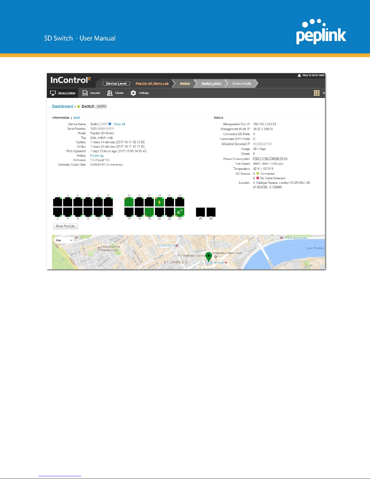
The Device Details page shows the following detailed information about the the SD-Switch:
Device Name
Firmware
Clients
Serial Number
Warranty Expiry Date
Power Consumption
Model
Management port IP
Fan Speed
Tags
Management VLAN IP
Temperature
Uptime
Connected GE ports
AC source
Online
Connected SFP+ ports
Location
First Appeared
InControl Detected IP
Port List
History (event log)
Usage
Page 16
Page 17
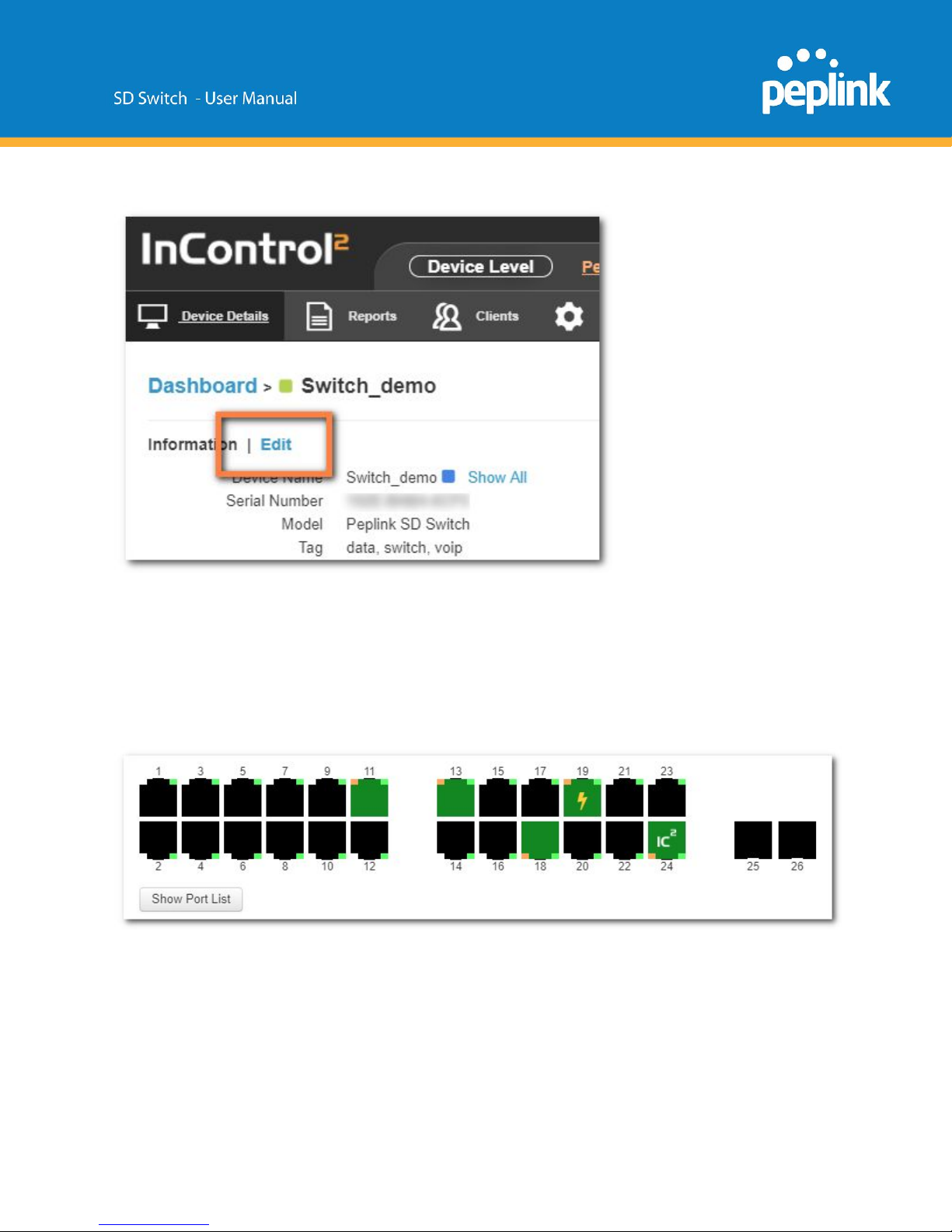
Device name, tags, location, and notes can be changed through the “Edit” link:
Select the Save button on the bottom of this page to save the settings and return to the device
details page.
Or Cancel to discard changes and return to the Device Settings page.
Port List
The Port List shows the available switch ports and their status.
When hovering over an individual port additional information is shown for that particular port.
Port 1 through 24 are RJ45 ports (ethernet)
Port 25 and 26 are SFP+ ports (fibre)
Page 18
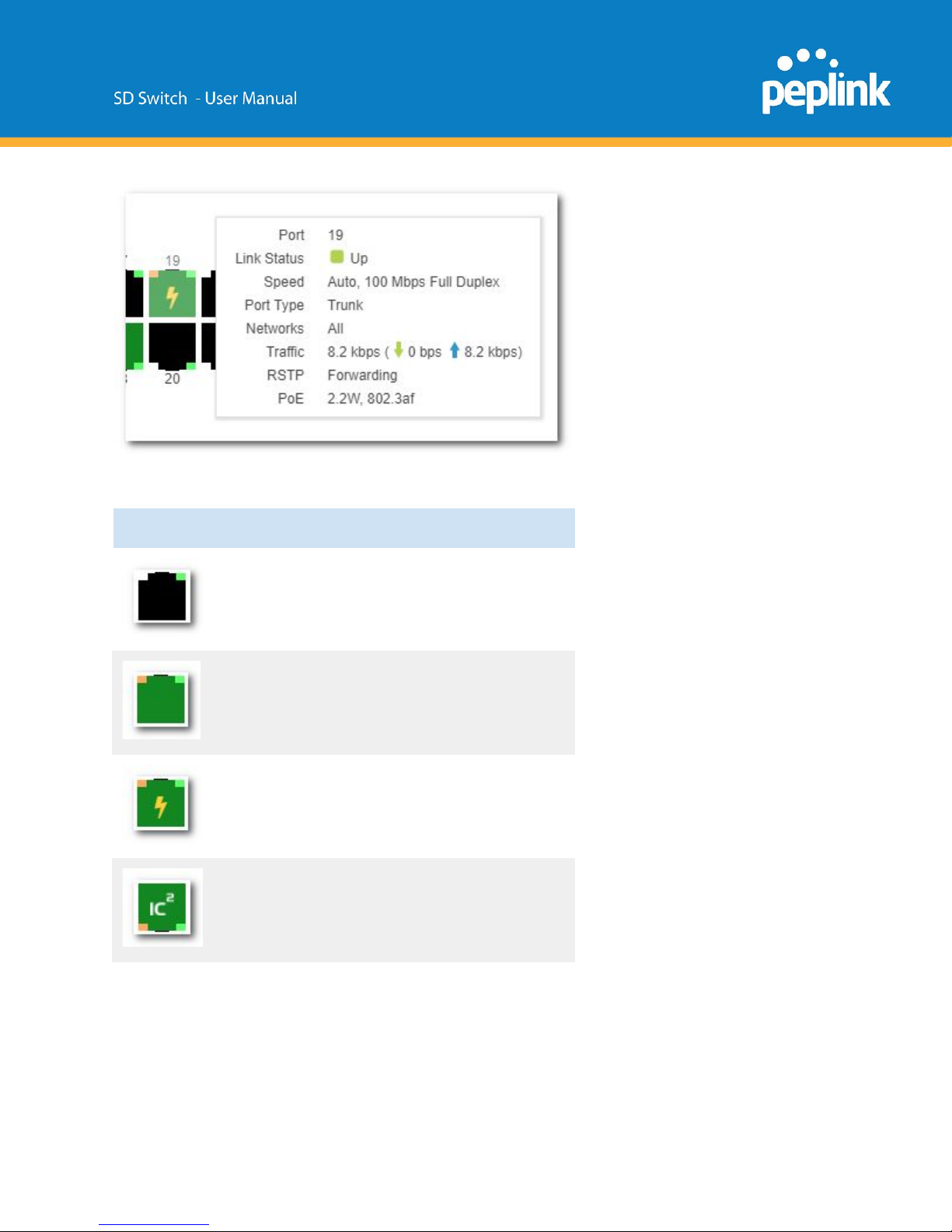
Port Icons Glossary
port down
port up - PoE not drawing power
port up -PoE drawing power
port up - link to InControl2
Page 19
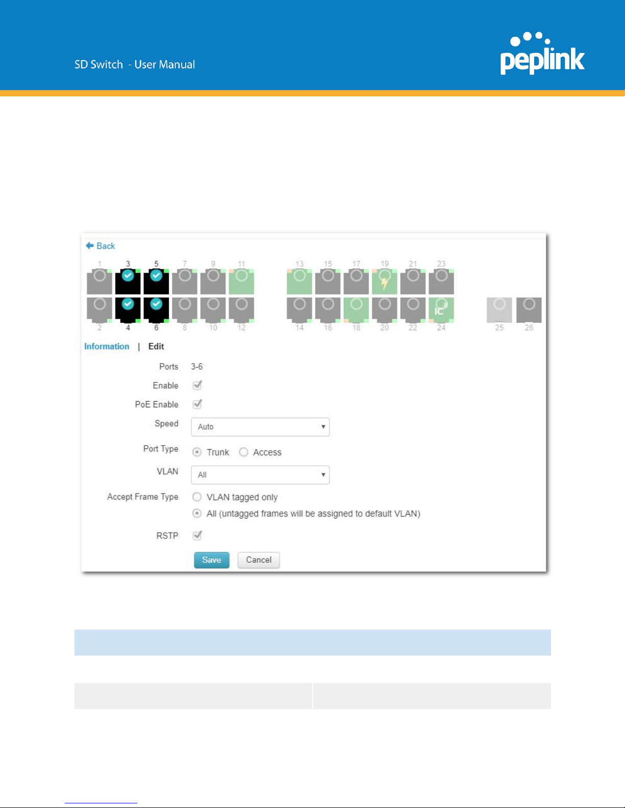
Port Details and Configuration
Additional port details appear when clicking on an individual port from the device details page.
Single or multiple ports can be selected and edited.
Configurable options (port 1 - 24)
Enable / disable
Enable or disable the switch port
PoE enable / disable
Enable or disable PoE on the port
Page 20
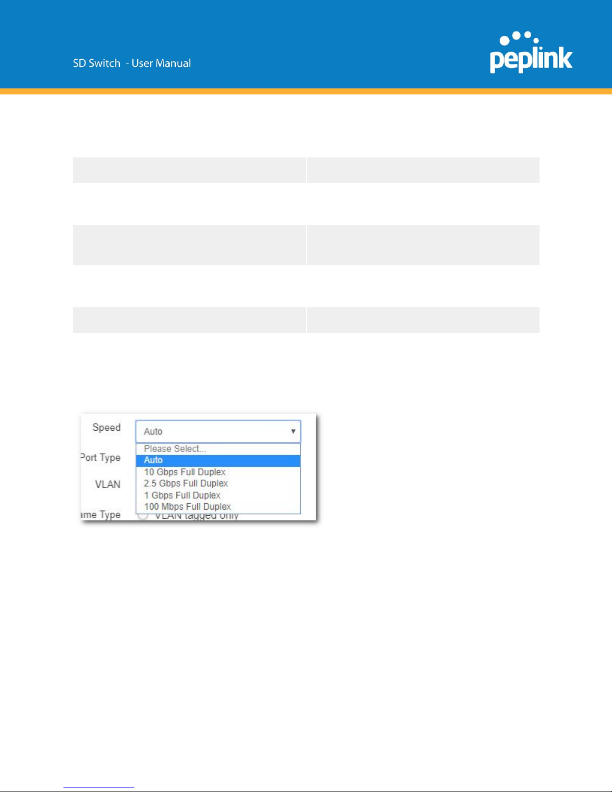
Speed
Select ports speeds 10 or 100 Mbps half or
full Duplex or 1 Gbps full Duplex.
Port Type
Trunk or Access port
VLAN
All or CUSTOM (select 1 or more existing
VLANs)
Accept Frame Type
Frame Types the port accepts (VLAN tagged
only, or All)
RSTP
Enable or disable RSTP (Rapid Spanning
Tree Protocol)
Notes
Add additional notes
LACP
Link Aggregation
Configurable options on port 25 and 26 (fibre) are similar as above; but configurable port
speeds are between 100 Mbps Full Duplex up to 10 Gbps Full Duplex.
Port List
The port list can be shown or hidden by clicking on the show/hide button under the ports.
Page 21
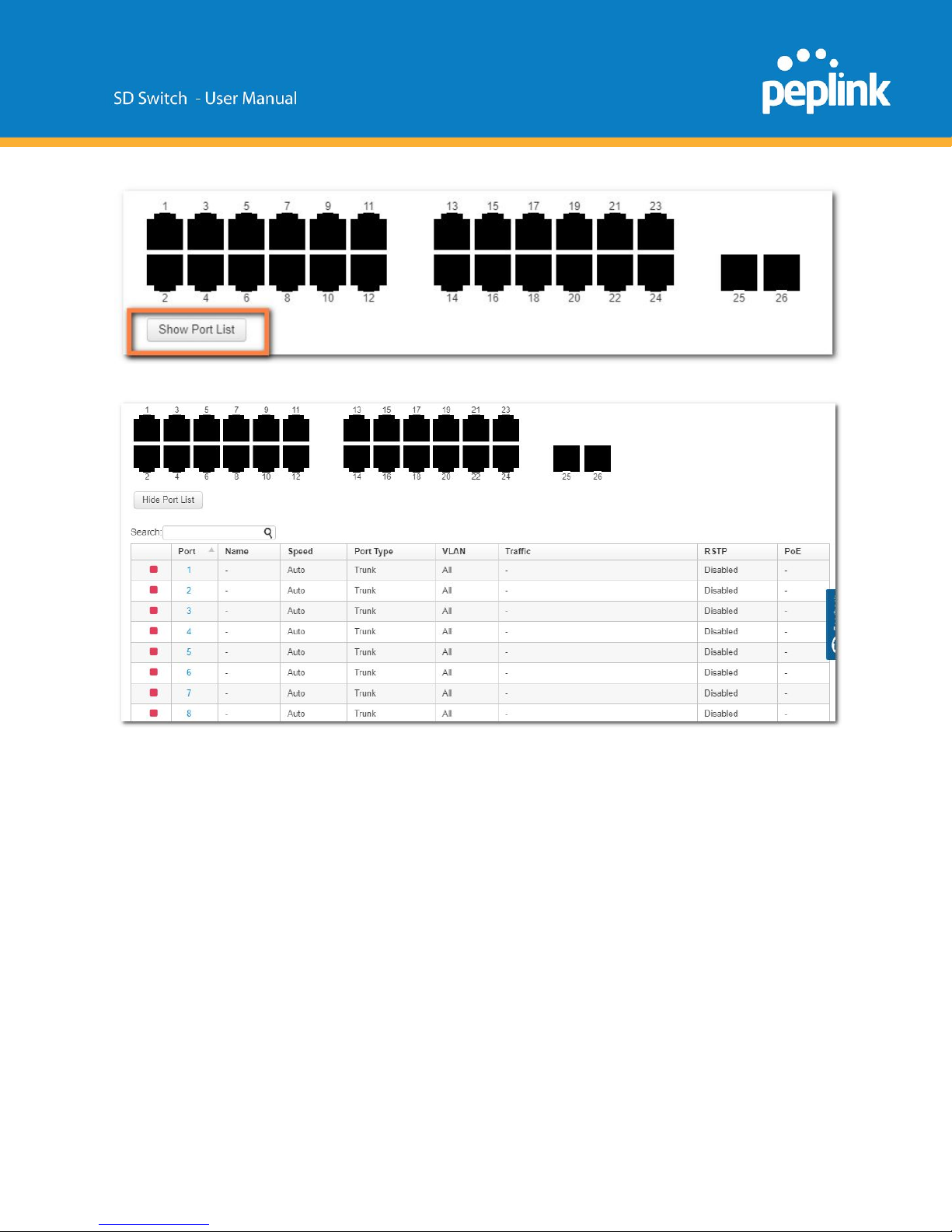
This will show (or hide) a table showing port details.
Page 22
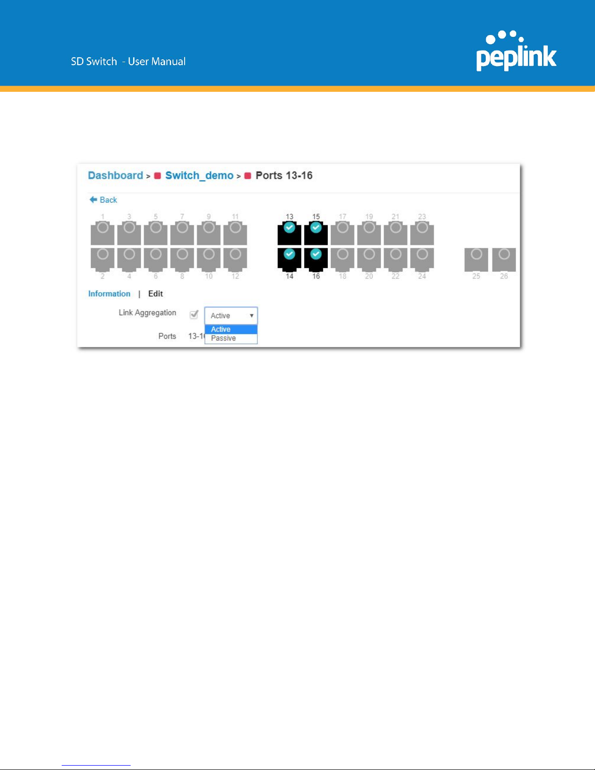
LACP - Link Aggregation
IEEE 802.3ad link aggregation enables you to group Ethernet interfaces to form a single link
layer interface, also known as a link aggregation group (LAG).
The maximum interfaces per LAG is 24.
The advantages of link aggregation in contrast with connections using an individual port include:
● higher throughput speed compared to an individual port
● higher accessibility
To configure a Link Aggregation Group (LAG), click Edit after selecting multiple ports.
Enable Link Aggregation by selecting the checkbox next to Link Aggregation.
The LAG can be set to Active or Passive.
LACP needs to be set to active on 1 side at least for LACP to work.
Details of Connected Clients and Hourly, Daily, or Monthly Power Usage for each Port is shown
in a graph on the same page.
Page 23
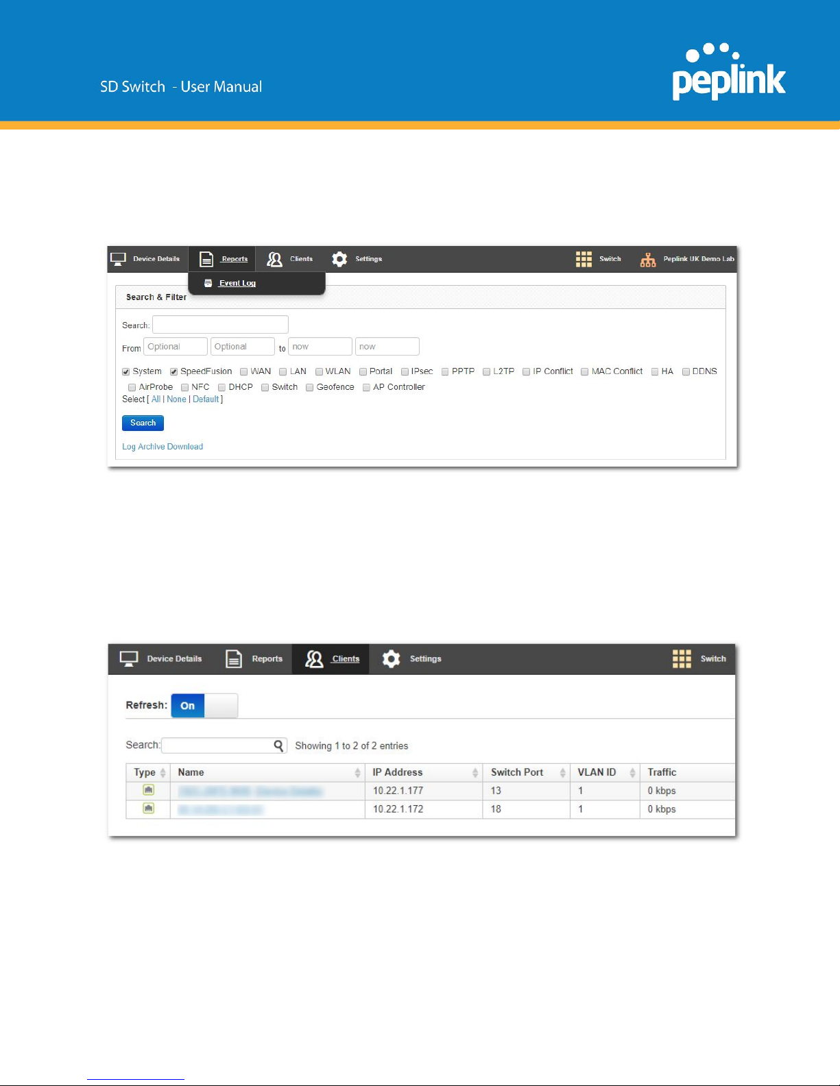
InControl Reports
Search through the SD Switch event logs, filter results by topic, time, client and details.
Download the event log in .csv format.
InControl Clients
View client details from client devices connected to the SD Switch.
Page 24
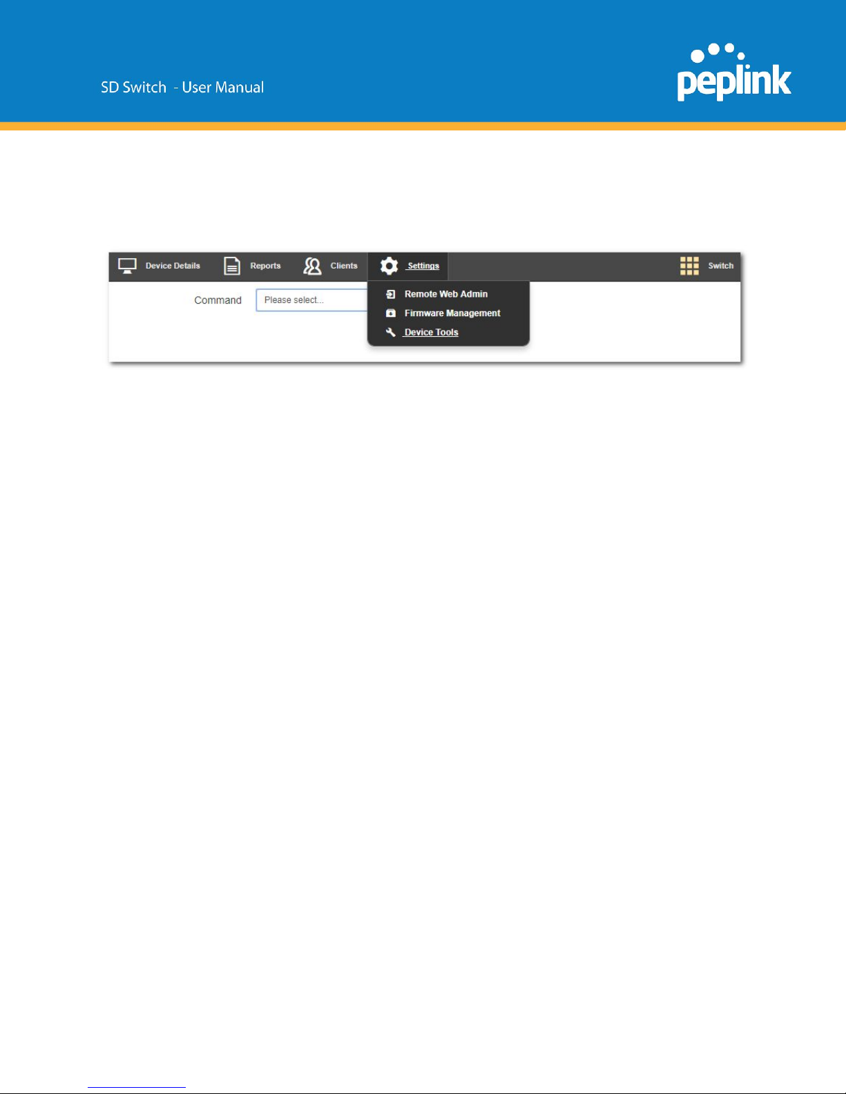
InControl Settings
The InControl Settings section gives access to the Remote Web Interface of the Switch. You
can also control firmware management for all devices in this InControl group and Device Tools.
Settings > Remote Web Admin
Remote Web Admin opens the web admin interface of the SD Switch in a separate tab.
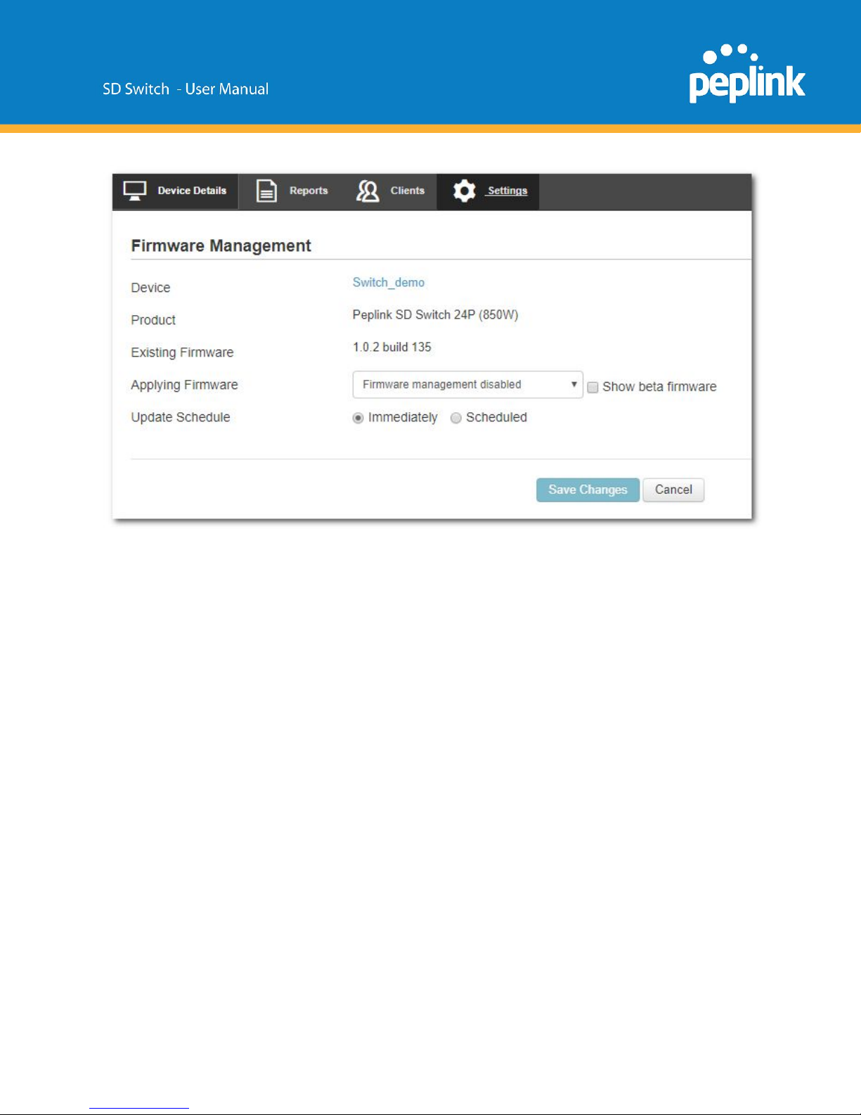
Settings > Firmware Management
Page 25
Standalone Configuration
When configuring the Switch in Stand Alone mode, Incontrol Management needs to be disabled.
After connecting to the management port and logging on to the Web Interface of the Switch,
browse to System > InControl and uncheck the “Allow InControl Management” option.
Page 26
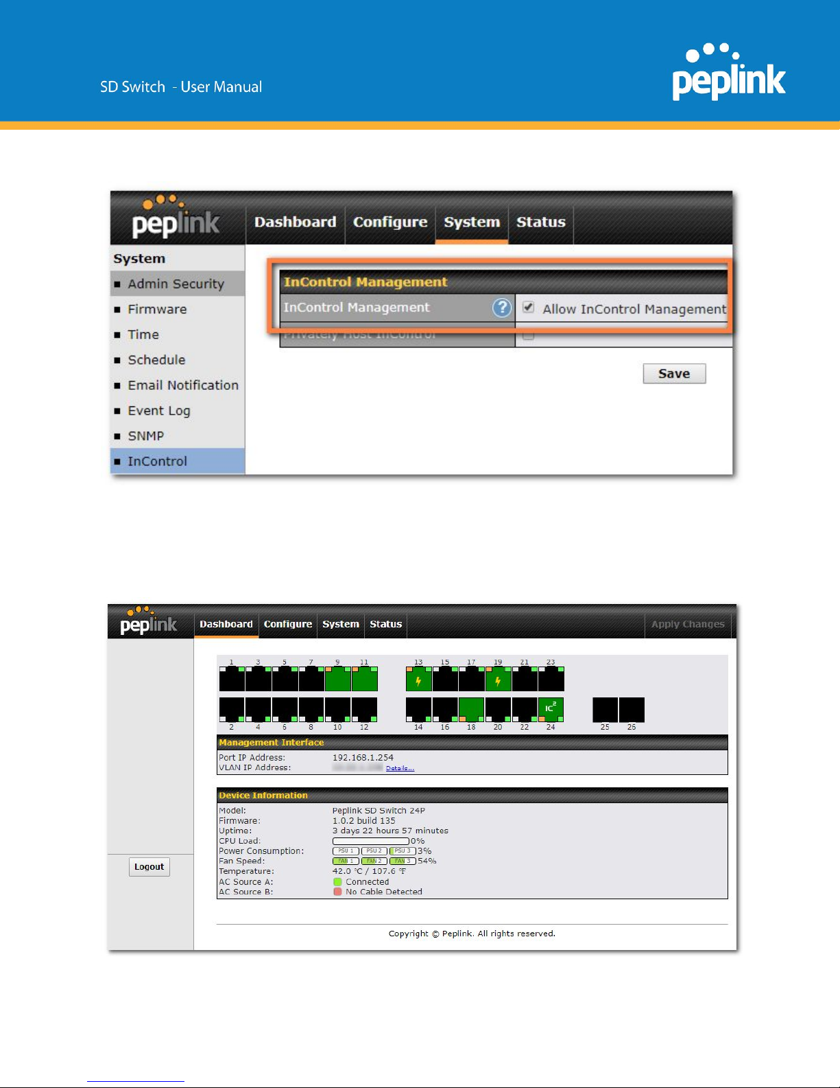
When this box is unchecked, your device will not be allowed to communicate with InControl.
Standalone menu options > Dashboard
Page 27
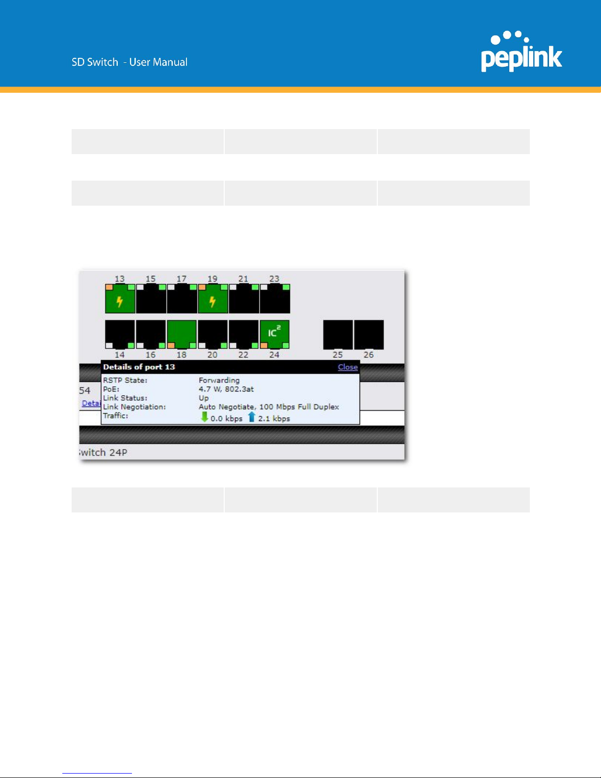
The Device Details page shows the following detailed information about the the SD-Switch.
Port Overview
Firmware
Fan Speed
Management port IP
Uptime
Temperature
Management VLAN IP
CPU Load
AC source status
Model
Power Consumption
Portlist
When hovering over a port, a popup window with port details displays the following information:
RSTP State
Link Status
Traffic
PoE
Link Negotiation details
Page 28
Standalone menu options > Configure > Network Settings
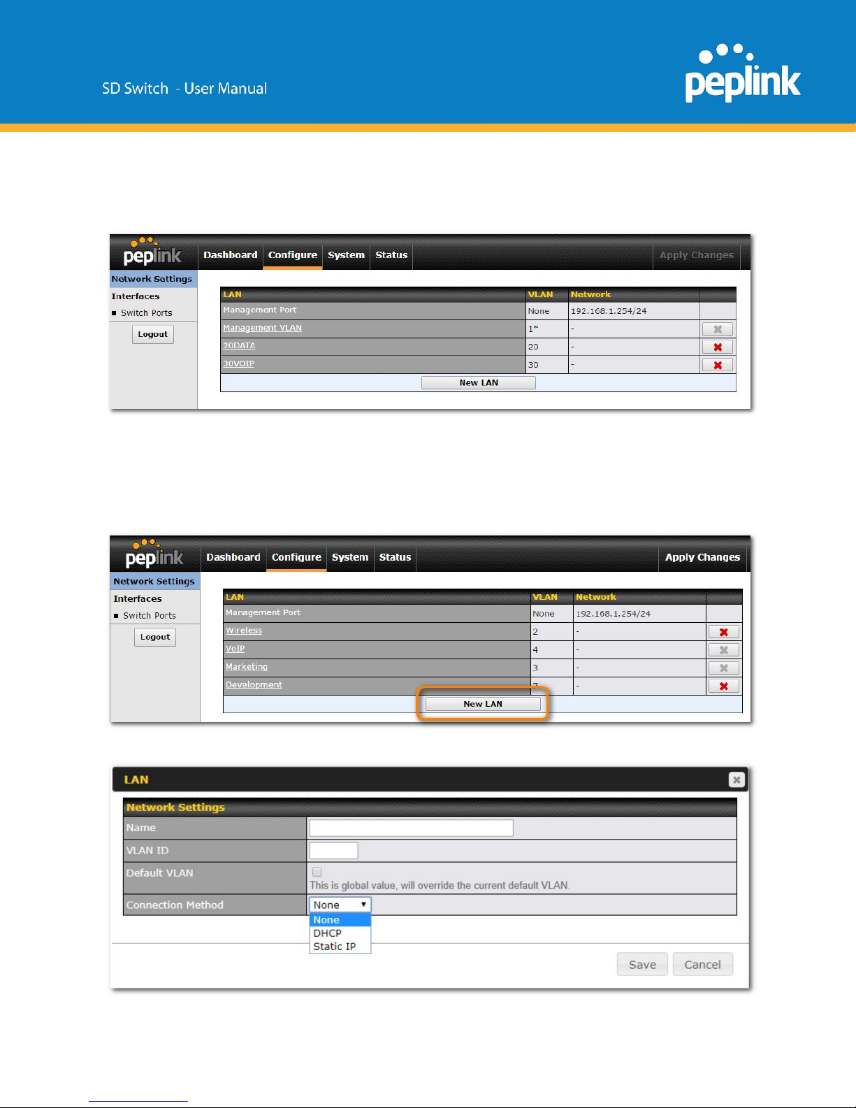
VLANs are configured in the Configure > Network Settings section of the Switch web
interface.
To define a new VLAN select the “New LAN” option.
On the following screen, enter your desired parameters.
Page 29
Click “Save” and then click the “Apply Changes” button on the top-right.
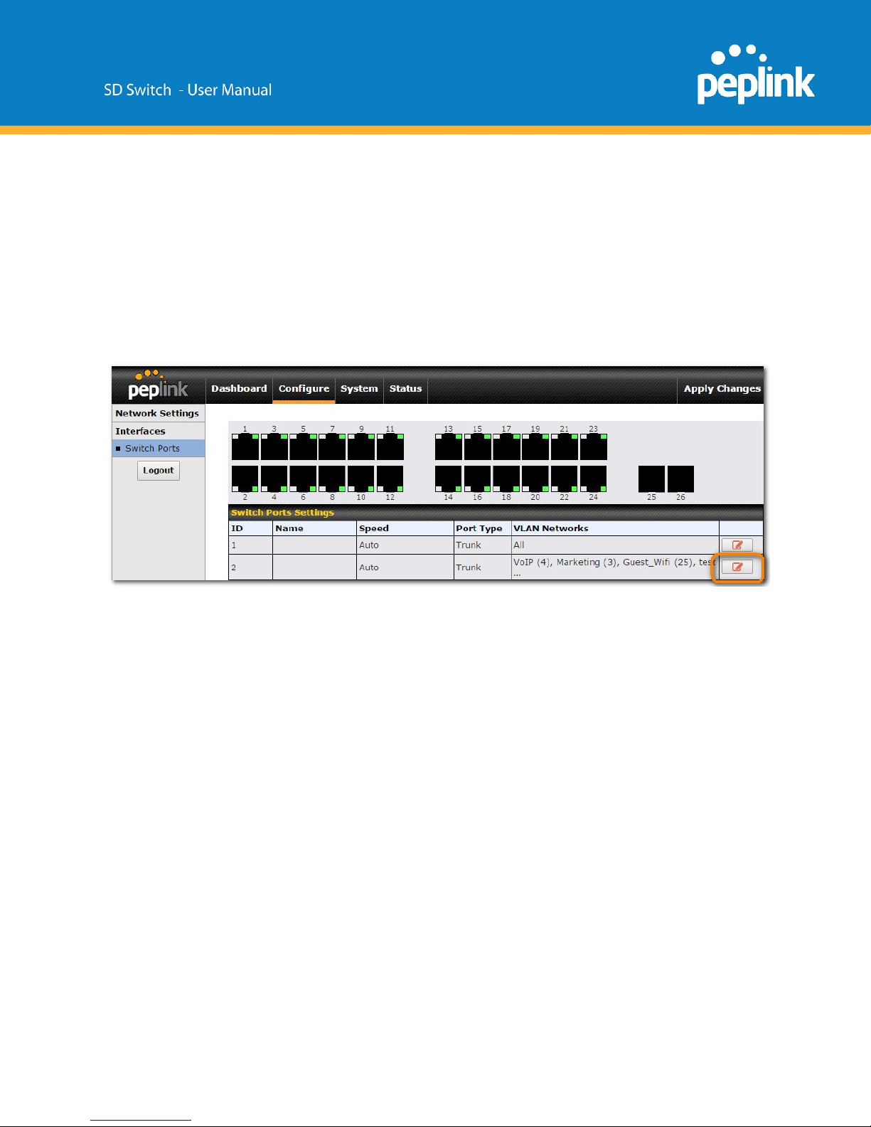
Standalone menu options > Configure > Interfaces > Switch Ports
For each port, you can set PoE scheduling, port type (Trunk and Access), as well as the VLAN
which they belong to.
Navigate to Configure > Switch Ports and then click the pen icon for the port you wish to
configure.
Page 30
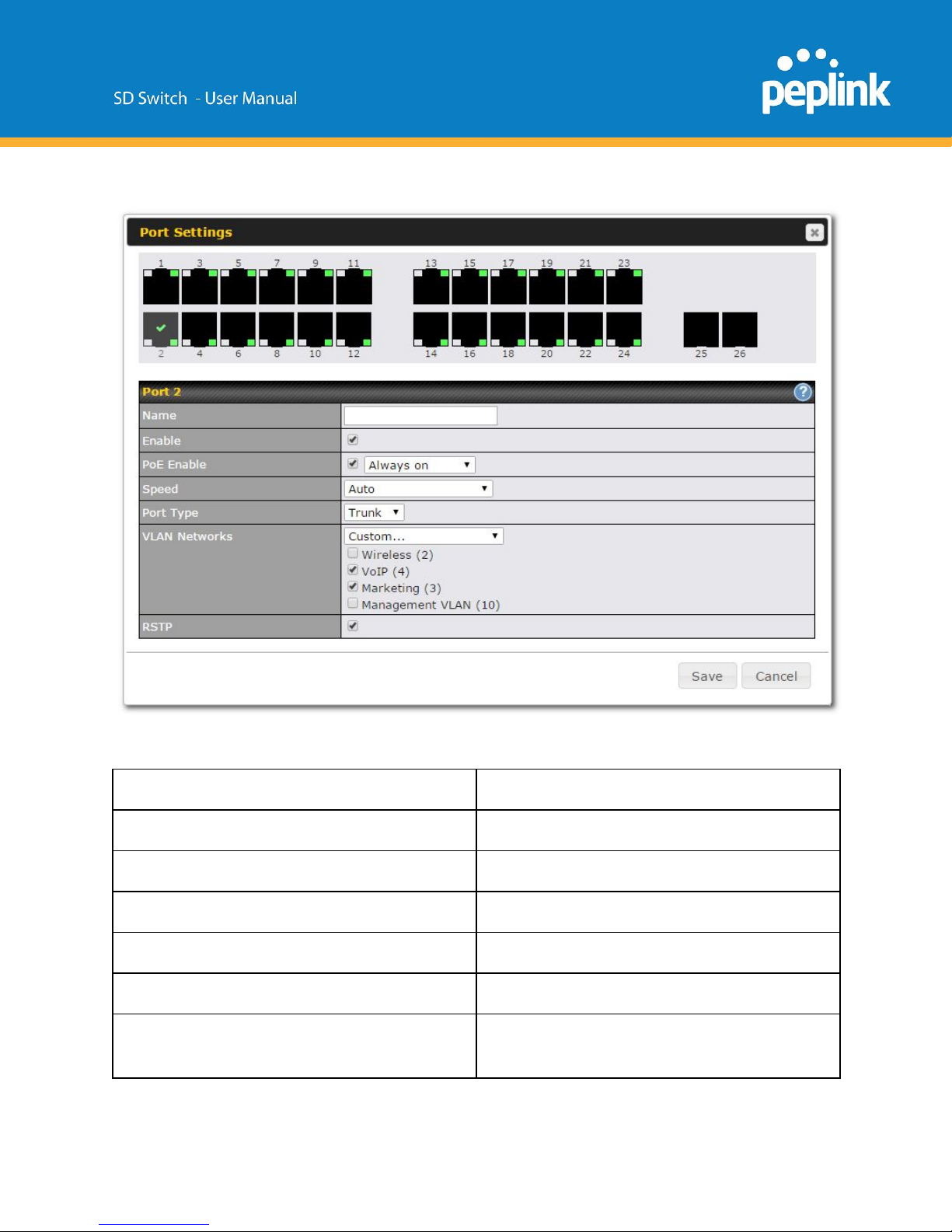
On the following screen, enter your desired parameters.
Configurable settings are:
Port Name
Enable /Disable Port
PoE
enable , disable or add a schedule
Port Speed
Port Type
Trunk or Access
VLAN Networks
select VLAN tags
RSTP
enable or disable Rapid Spanning Tree
Protocol
Page 31
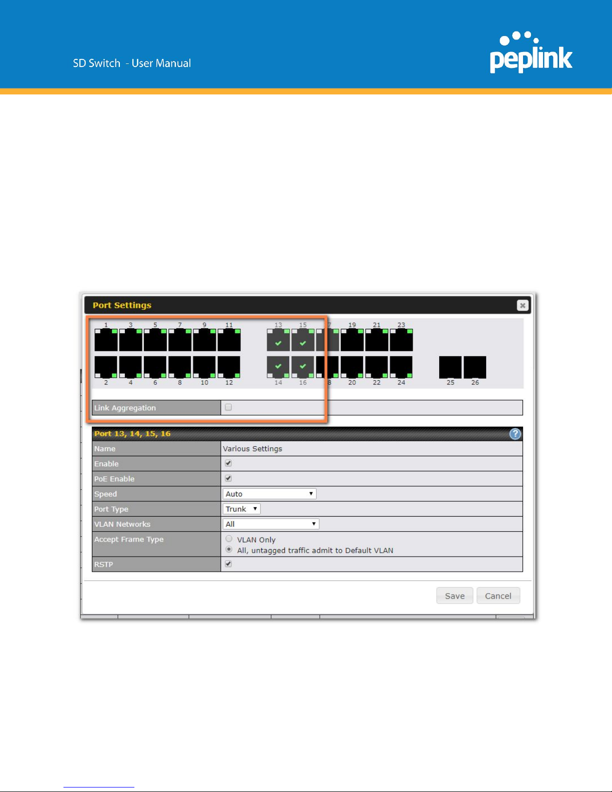
After making changes click “Save” and then click the “Apply Changes” button on the top-right
corner of the interface.
LACP (802.3ad) Configuration
LACP is part of the IEEE specification 802.3ad and allows you to bundle several physical ports
to form a single logical channel.
Bundling multiple physical ports into a single logical link allows you to increase throughput
beyond the limitations of a single connection and provides redundancy in case one link goes
down.
Select multiple ports by clicking on them and selecting the Link Aggregation checkbox to
enable link aggregation for the selected ports.
Page 32
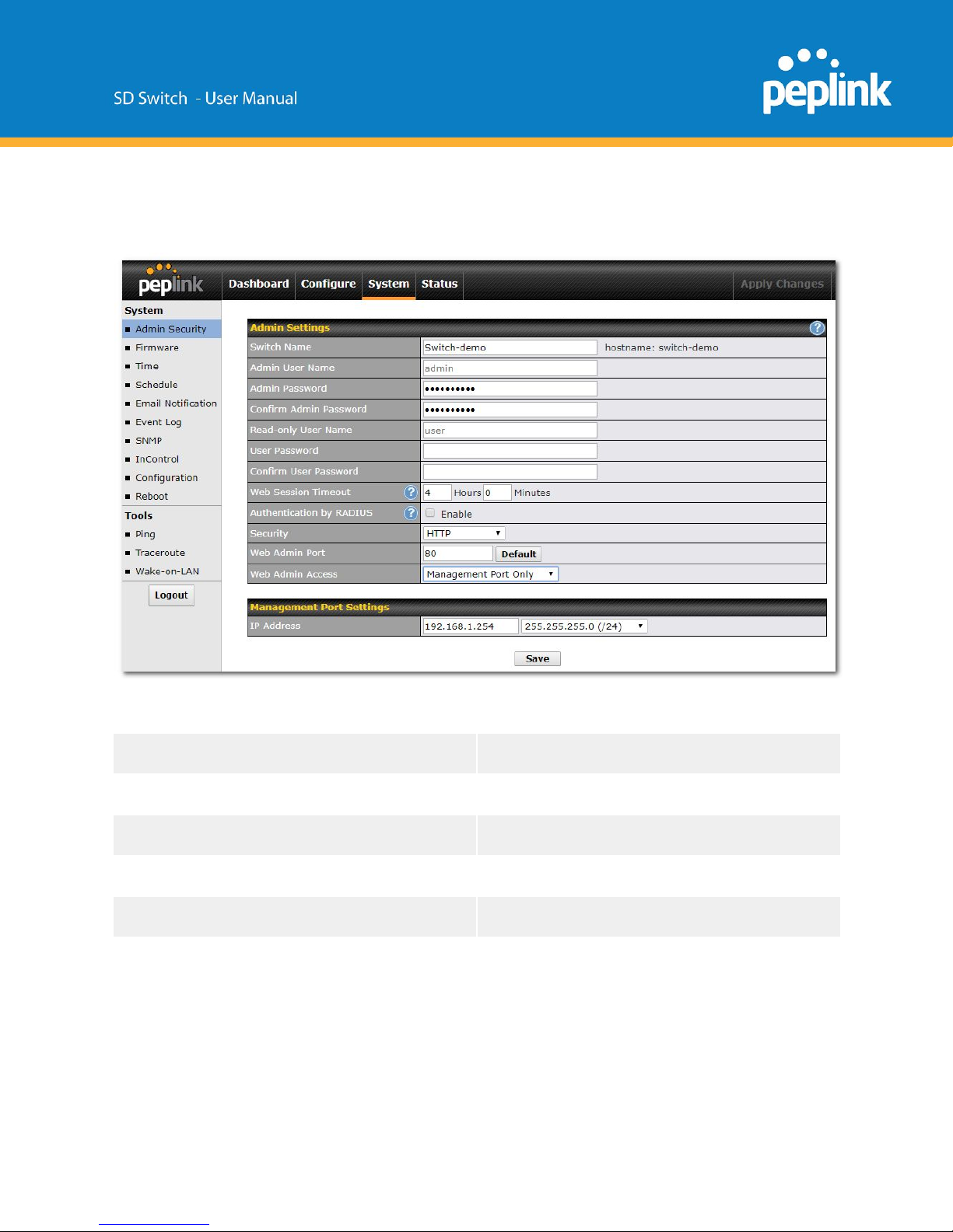
Standalone menu options > System > Admin Security
The Admin Security page allows you to configure the following settings:
Switch Name
Switch hostname
Admin user name
Admin Password
Read-only username
User password
Web Session Timeout
A web login session will be logged out
automatically when it has been idle longer
than the Web Session Timeout.
Before the session expires, you may click the
Logout button in the Web Admin to exit the
session.
Page 33
0 hours 0 minutes signifies an unlimited
session time. This setting should be used
only in special situations as it will lower the
system security level if users do not logout
before closing the browser.
The default setting is 4 hours 0 minutes
Security
HTTP / HTTPS sessions or both are allowed
to connect to the web admin interface.
Web Admin Port
Port to connect to the web admin interface
(default port is 80 for HTTP and 443 for
HTTPS).
Web Admin Access
Access only allowed through Management
Port, or through the Management port and a
specific VLAN.
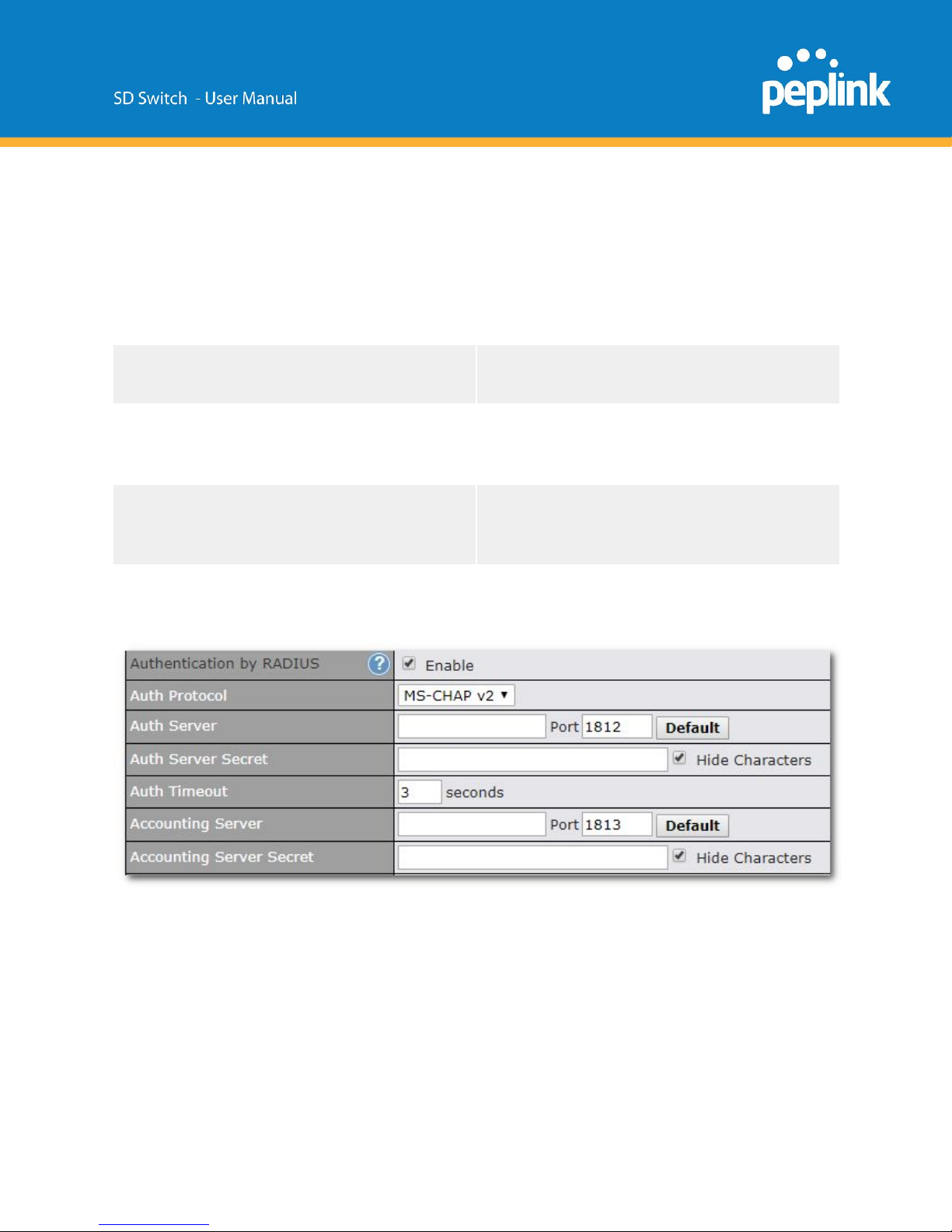
Authentication by Radius
When this option is enabled, the web admin will authenticate using an external RADIUS server.
Authenticated users are treated as "admin" users with full read-write permission. Local "admin"
and "user" accounts will be disabled.
However, when the device fails to communicate with the RADIUS server, local accounts are
enabled to allow emergency access.
The Authentication Protocols supported are MS-CHAPv2 and PAP.
Management Port Settings
Page 34
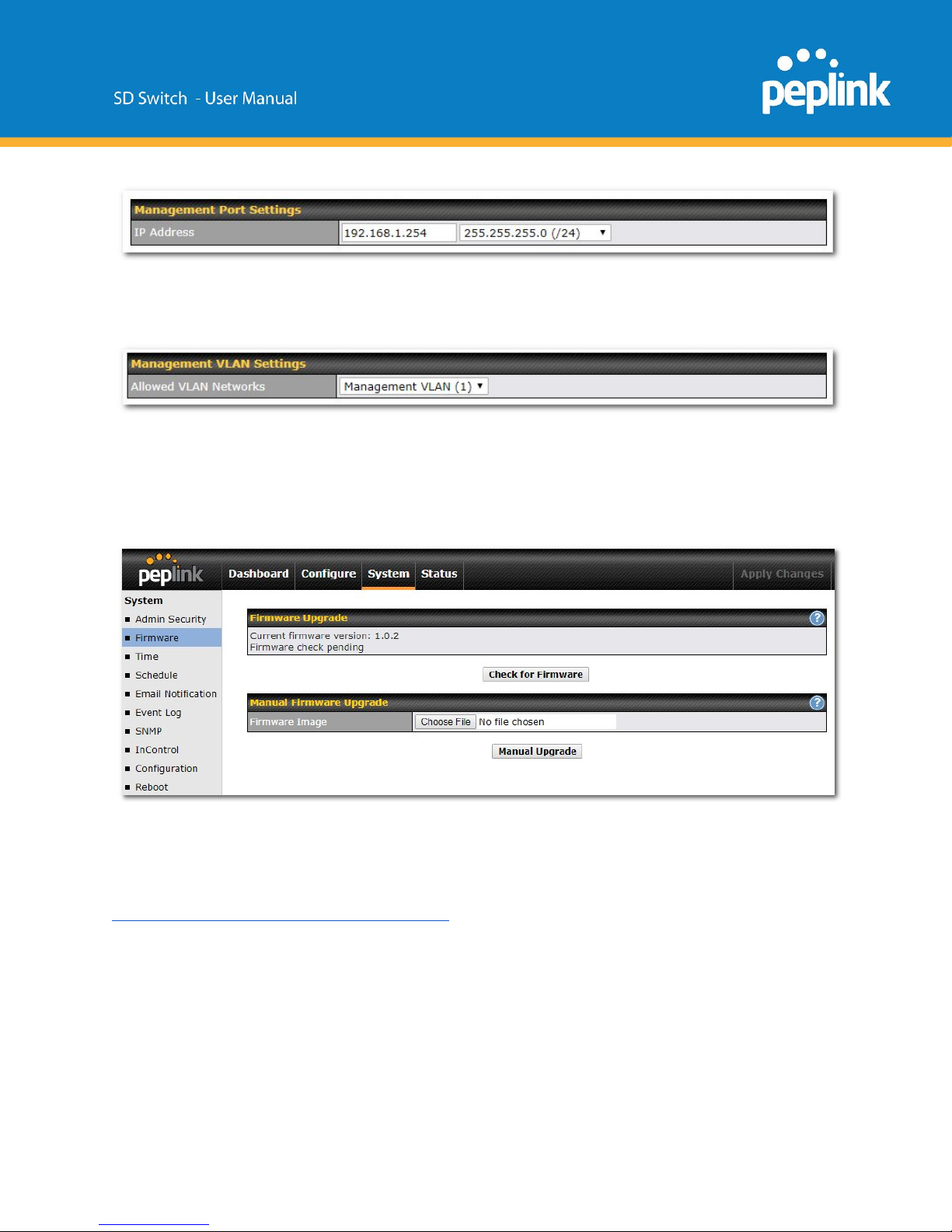
Configure the management port IP address and subnet mask.
Management VLAN Settings
Select the allowed VLAN network to manage the SD-Switch.
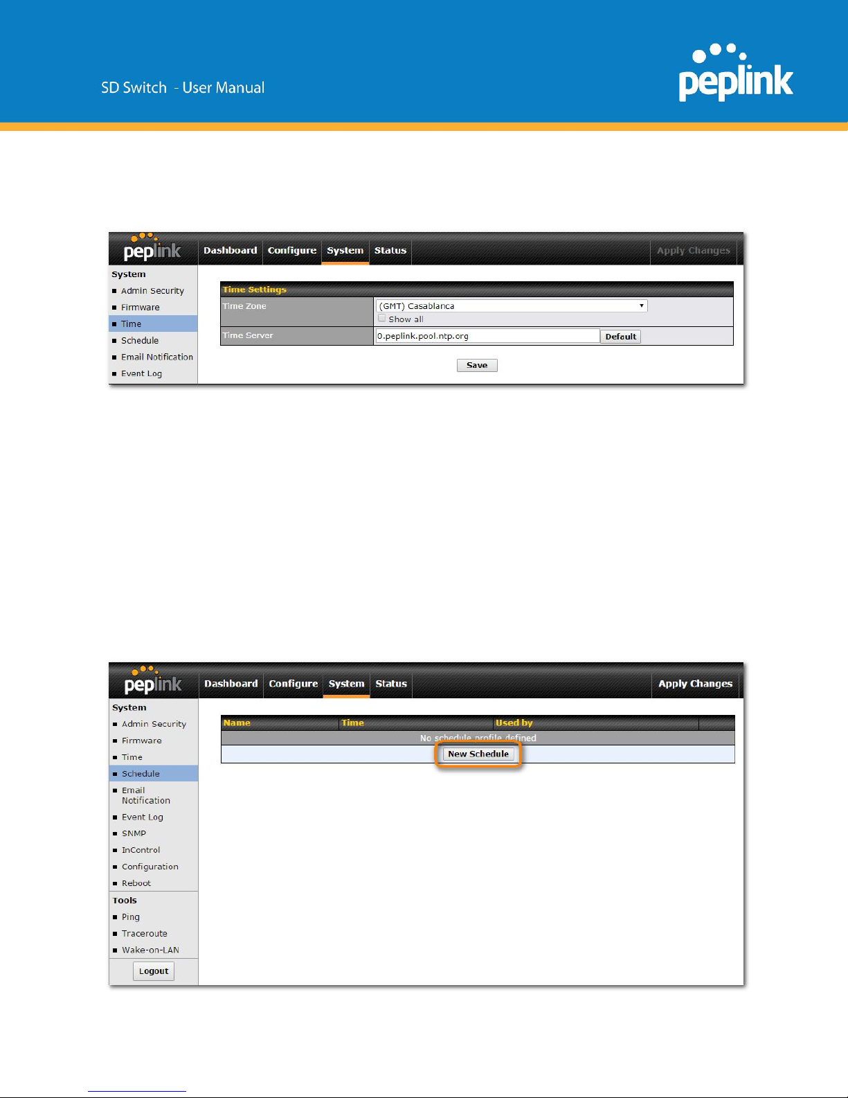
Standalone menu options > System > Firmware
You can either click the Check for Firmware button to contact the firmware server to check for
new firmware or manually upgrade the SD-Switch with a downloaded firmware file.
Firmware can be downloaded from the Peplink website:
https://www.peplink.com/support/downloads/
Page 35
Standalone menu options > System > Time
This section allows you to select a Time Zone and configure a Time Server.
Standalone menu options > System > Schedule
Schedules can be created and applied to port PoE settings.
Establish a Scheduling Profile
To Define a schedule, navigate to System > Schedule and the click the “New Schedule”
button.
Page 36
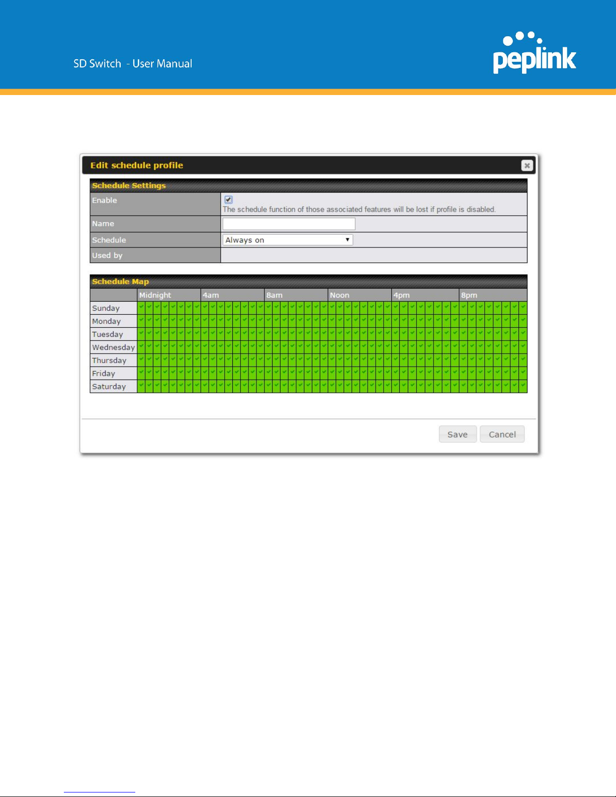
The following screen will appear. Enter the desired name and click the grid to define your
schedule and then click “Save”.
Click the “Apply Changes” text on the top-right corner to save your changes.
Page 37
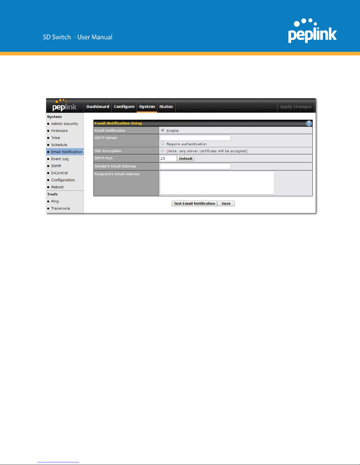
Standalone menu options > System > Email Notification
The feature Email Notification allows email to be sent to the listed recipient email addresses
when the following events take place:
● Email notification test
● A new firmware version is available
● Health status changes for any WAN connection
● VPN status changes
● Bandwidth usage has reached 75% of the allowance
● Bandwidth usage has reached 95% of the allowance
Click the button Test Email Notification and click Send Test Notification to send a testing
email.
Page 38
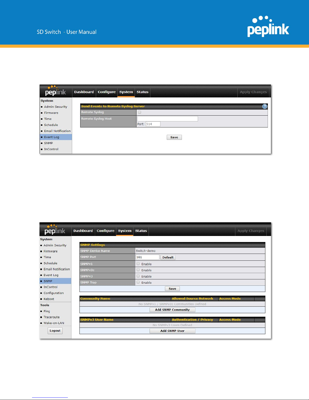
Standalone menu options > System > Event Log
Remote Syslog allows syslog messages to be sent to a specified remote syslog server.
You can configure a remote syslog host either in the form of an IP address or a server domain
name.
The default Syslog port used and configured is UDP 514; this is an option that can be
configured to use a different port.
Standalone menu options > System > SNMP
SNMP or Simple Network Management Protocol is an open standard that can be used to
collect information about the Peplink Balance unit.
Page 39
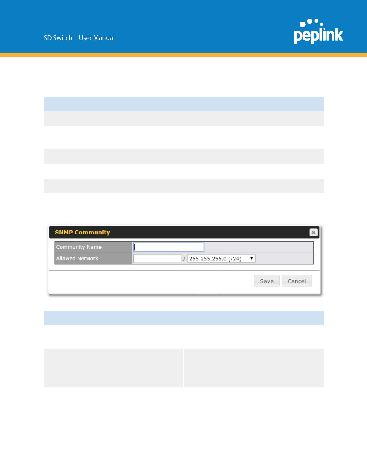
SNMP Settings
SNMP Device Name
This field shows the router name defined at System>Admin Security
SNMP Port
This option specifies the port which SNMP will use. The default port is
161.
SNMPv1
This option allows you to enable SNMP version 1.
SNMPv2
This option allows you to enable SNMP version 2.
SNMPv3
This option allows you to enable SNMP version 3.
To add a community for either SNMPv1 or SNMPv2, click the Add SNMP Community
button in the Community Name table, upon which the following screen is displayed:
SNMP Community Settings
Community Name
This setting specifies the SNMP community
name.
Allowed Source Subnet Address
This setting specifies a subnet from which
access to the SNMP server is allowed. Enter
subnet address here (e.g., 192.168.1.0) and
select the appropriate subnet mask
To define a username for SNMPv3, click Add SNMP User in the SNMPv3 User Name
table, upon which the following screen is displayed:
Page 40
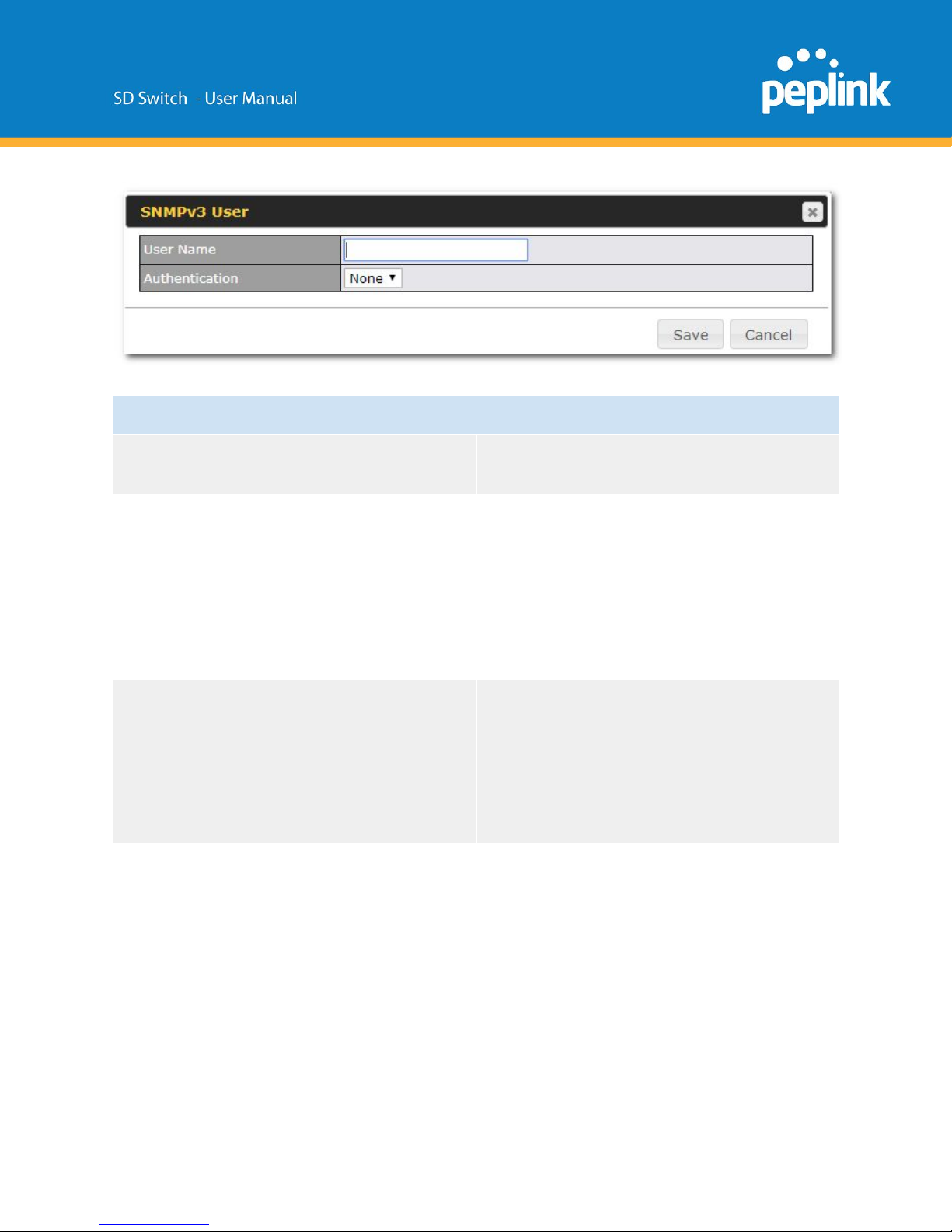
SNMPv3 User Settings
User Name
This setting specifies a user name to be used
in SNMPv3.
Authentication Protocol
This setting specifies via a drop-down menu
one of the following valid authentication
Protocols:
● NONE
● MD5
● SHA
When MD5 or SHA is selected, an entry field
will appear for the password.
Privacy protocol
This setting specifies via a drop-down menu
one of the following valid privacy
Protocols:
● NONE
● DES
When DES is selected, an entry field will
appear for the password.
Standalone menu options > System > InControl
InControl is a cloud-based service which allows you to manage all of your Peplink and
Pepwave devices with one unified system. With it, you can generate reports, gather
statistics, and configure your devices automatically. All of this is now possible with
InControl.
Page 41
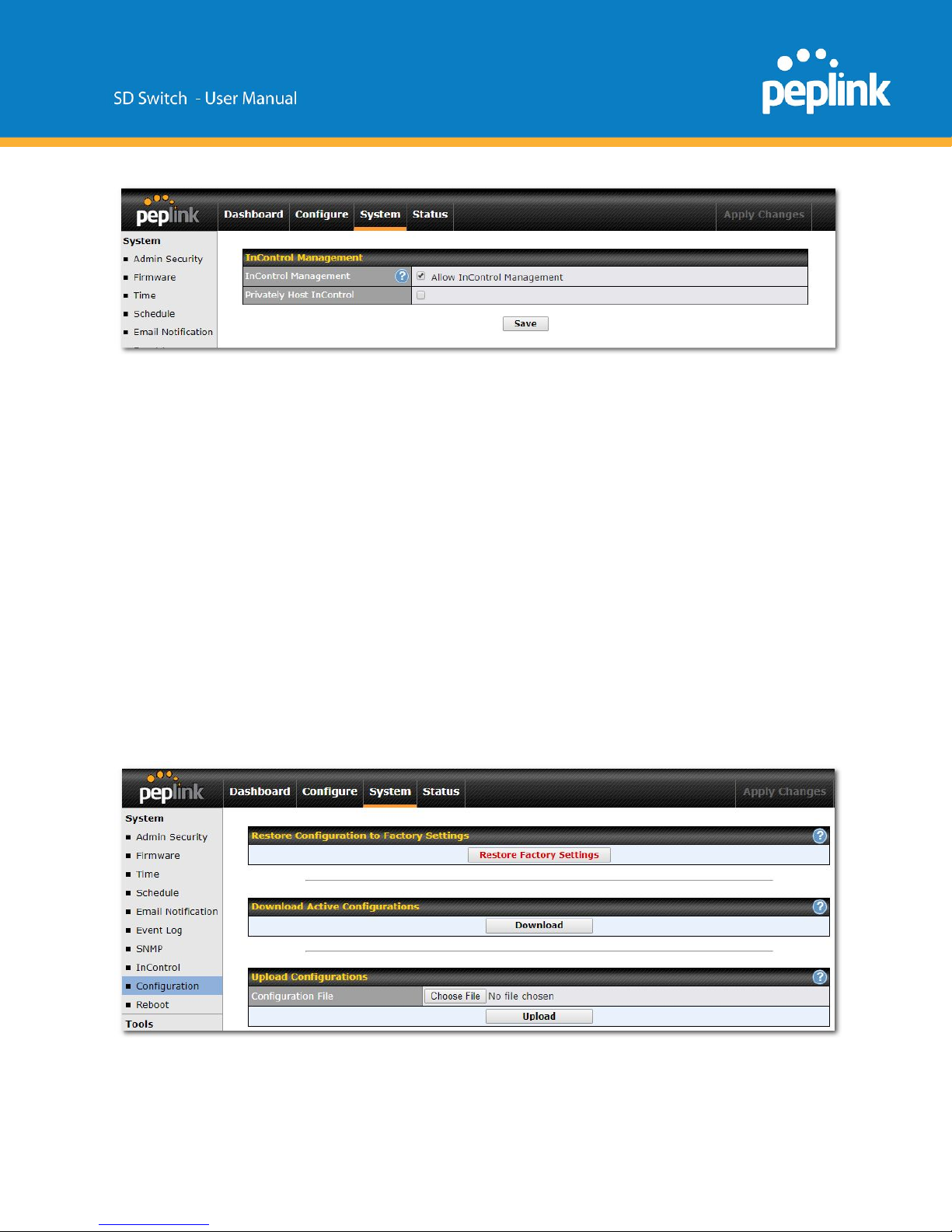
When this checkbox is checked, the device's status information will be sent to the
Peplink InControl system.
This device's usage data and configuration will be sent to the system if you enable the features
in the system.
Alternately, you could also privately host InControl. Simply check the box beside the “Privately
Host InControl” open, and enter the IP Address of your InControl Host.
You can sign up for an InControl account at https://incontrol2.peplink.com.
You can register your devices under the account, monitor their status, see their usage reports,
and receive offline notifications.
Standalone menu options > System > Configuration
Backing up Peplink Balance settings immediately after successful completion of initial
setup is strongly recommended. The functionality to download and upload Peplink
Balance settings is found at System>Configuration.
Page 42
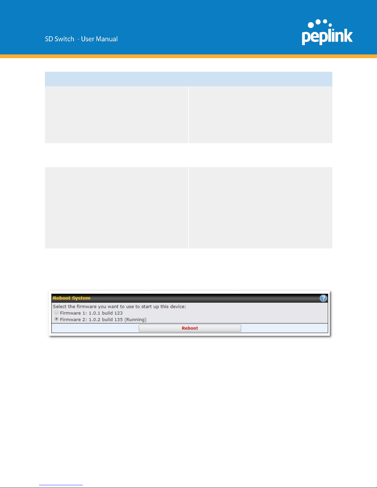
Configuration
Restore Configuration to Factory Settings
The Restore Factory Settings button is to
reset the configuration to factory default
settings.
After clicking the button, you will need to click
the Apply Changes button on the
top right corner to make the settings effective.
Download Active Configurations
Click Download to backup the current active
settings.
Upload Configurations
To restore or change settings based on a
configuration file, click Choose File to locate
the configuration file on the local computer,
and then click Upload.
The new settings can then be applied by
clicking the Apply Changes button on the
page header, or you can cancel
the procedure by pressing discard on the
main page of the web admin interface.
Standalone menu options > System > Reboot
This page provides a reboot button for restarting the system. For maximum reliability,
the Peplink Balance Series can equip with two copies of firmware, and each copy can
be a different version. You can select the firmware version you would like to reboot the
device with. The firmware marked with (Running) is the current system boot up
firmware.
Please note that a firmware upgrade will always replace the inactive firmware Partition.
Page 43
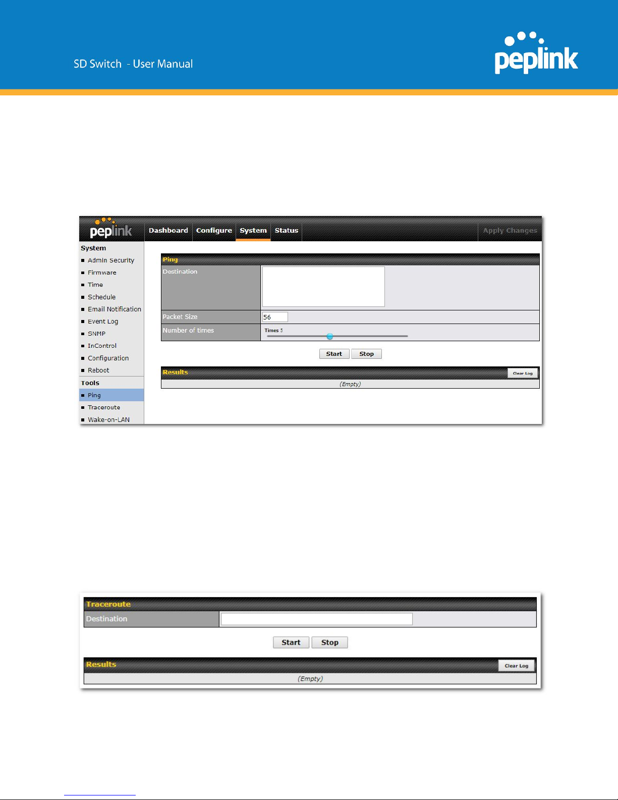
Standalone menu options > System > Tools
Ping
The ping test tool sends pings through a specified Ethernet interface or a SpeedFusion VPN
connection.
You can specify the number of pings in the field Number of times to a maximum number of 10
times.
Packet Size can be set to a maximum of 1472 bytes.
A system administrator can use the ping utility to manually check the connectivity of a particular
LAN/WAN connection.
Traceroute
Page 44
The traceroute test tool traces the routing path to the destination through a particular
Ethernet interface or a SpeedFusion connection.
A system administrator can use the traceroute utility to analyze the connection path of a
LAN/WAN connection.
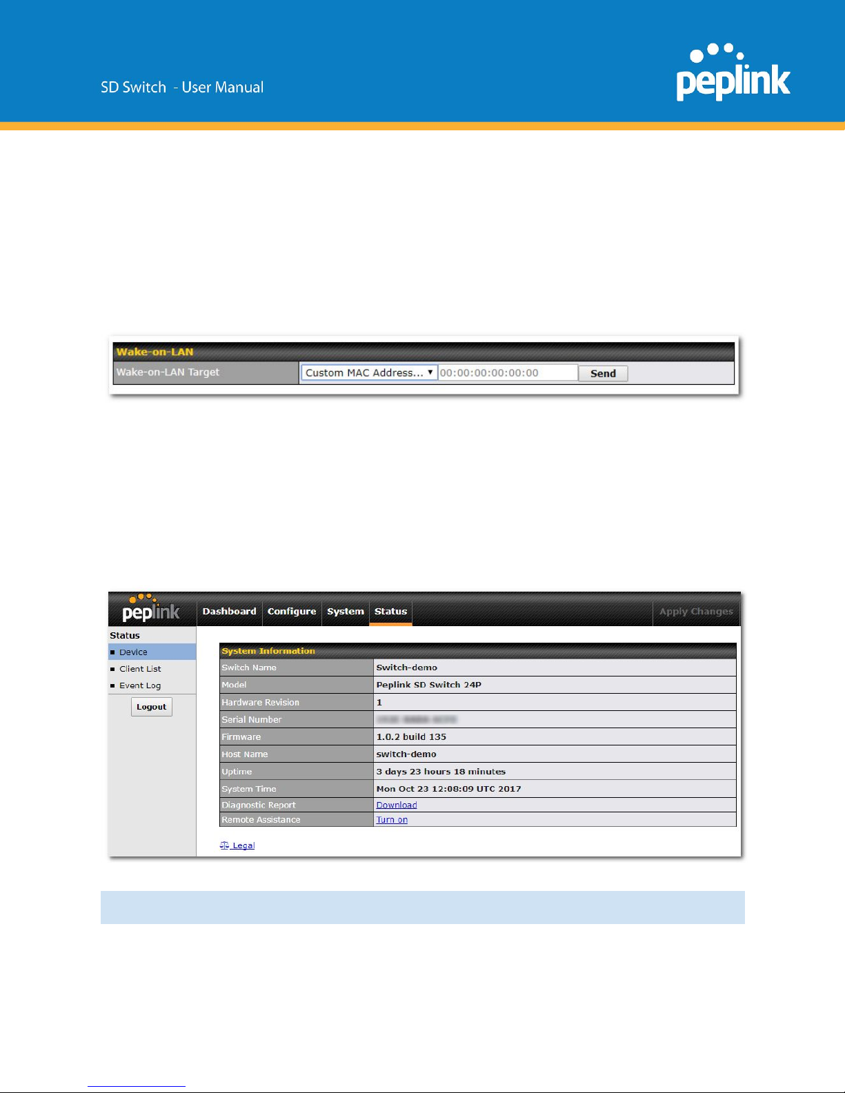
Wake-on-LAN
Wake-on-LAN is a technology that allows a network professional to remotely power on a
computer or to wake it up from sleep mode (if this is supported by the client device).
Select a client from the drop-down list and click Send to remotely power on the client
device.
Standalone menu options > Status > Device
This page displays the device’s system information.
System information
Switch name
This is the name specified in the Switch
Name field located at System>Admin
Page 45

Security.
Model
This shows the model name of the device.
Hardware Revision
This shows the hardware version of this
device.
Serial Number
This shows the serial number of this device.
Firmware
This shows the firmware version this device is
currently running.
Uptime
This shows the length of time since the
device has been rebooted.
System Time
This shows the current system time.
Diagnostic report
The Download link is for exporting a
diagnostic report file required for system
investigation.
Remote Assistance
Click Turn on to enable remote assistance.
Legal
The Legal link opens a webpage with legal
information.
Page 46
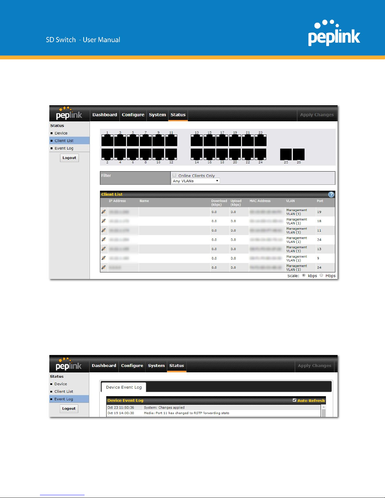
Standalone menu options > Status > Client List
This page lists all clients accessing the SD-Switch from the LAN.
It lists client IP addresses from one or more VLANs, names, current download and upload rate,
MAC address, VLAN, and Port used.
Assign a name to a client by clicking on the Name field of the client and inputting a name.
Standalone menu options > Status > Event Log
The log section displays a list of events that has taken place on the SD-Switch.
Check Auto Refresh to refresh log entries automatically.
Page 47

Click the Clear Log button to clear the log.
Additional troubleshooting resources
Peplink Knowledgebase: https://forum.peplink.com/c/knowledgebase
Peplink Community Forums: https://forum.peplink.com/
Contact Us:
Sales http://www.peplink.com/contact/sales/
Support http://www.peplink.com/contact/
Certified Peplink Partner http://www.peplink.com/partners/channel-partner-program/
 Loading...