

Page 1
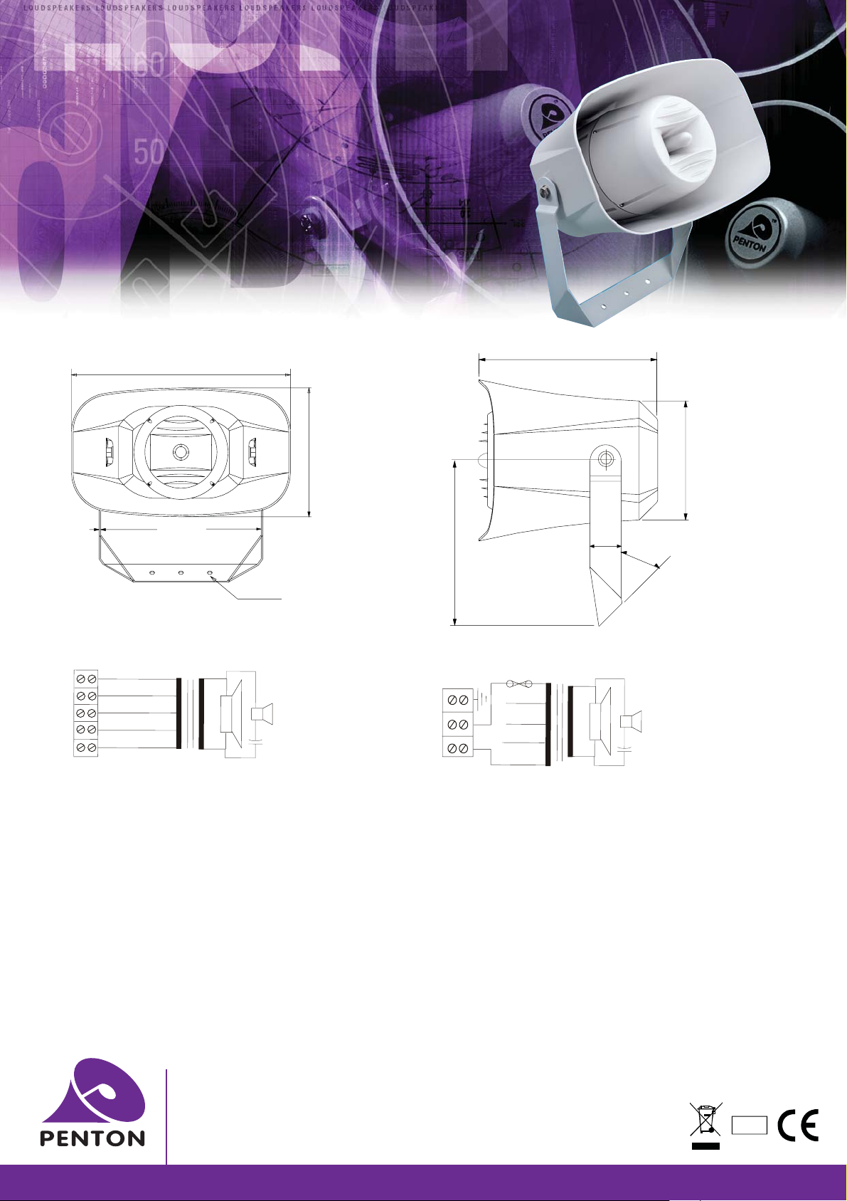
MUSIC HORN
LOUDSPEAKERS
MSH30/T
f
MSH30/TC
f
INSTALLATION INSTRUCTIONS
442
287.5
unit: mm
260
3
334
Front View Side View
Units: mm
3 x 10mm dia holes
MSH30/T Circuit diagram 100V Common
Black
3.75W
Yellow
Blue
Red
7.5W
15W
30W
Ceramic
terminal
Orange
STEP 1
f
Remove the back lid of the unit and connect input cable to the
ceramic terminal block through the cable gland provided.
STEP 2
f
On removing the back lid of the horn loudspeaker you will observe a
3 way ceramic or a 5 way plastic terminal block that is connected to
the 100 volt line transformer. Fit the 100 volt line input cable to the
selected volume (watts) that you require. For more information, look
inside the lid where you will find a list of matching cable colours to
watts, from 30 watts down to 3.75watts.
To change the tapping select the appropriate colour (black is always
common) and connect accordingly.
STEP 3
f
On selecting the tapping required and wiring the same, secure the
cable gland tight into the back lid of the chamber.
192
Back lid
270
MSH30/TC Circuit diagram 100V Common
Thermal Fuse
3.75W
block
STEP 4
f
Around the inner section of the chamber, where the back lid was
removed, a rubber gasket is located, please make sure that it is in
place when refitting to avoid water penetration
STEP 5
f
Drill the mounting location holes for the unit in line with the U bracket
(2 holes 60 mm apart) in the surface where the loudspeaker is to be
located. It is not necessary to use the central mounting hole in the
bracket unless the loudspeaker is located on a pole mount clamp
STEP 6
f
Mount the speaker in the required location specified by an acoustic
engineer
STEP 7
f
Before putting a 100 volt line through the unit it is advisable to check
the impedance of the circuit.
7.5W
15W
30W
50
45
O
Penton UK Ltd
Unit 2 Teville Industrials | Dominion Way | Worthing | West Sussex | BN14 8NW
T: +44 (0)1903 215315 | F: +44(0)1903 215415 | E: [email protected]
www.pentonuk.co.uk
NOVEMBER 2011
RoHS
 Loading...