

Page 1
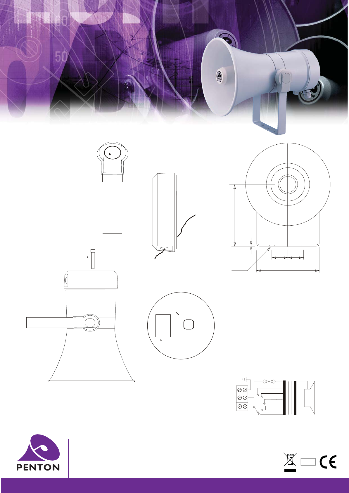
METAL COLUMN
LOUDSPEAKERS
MHS20/TC
f
INSTALLATION INSTRUCTIONS
STEP 1
f
Remove bolt cover cap.
STEP 2
f
Loosen bolt.
STEP 3
f
Adjust to required angle in a
ratchet formation.
STEP 4
f
Tighten bolt & replace cover.
STEP 6
f
Gland cable through
back lid.
unit: mm
5
2.
6
1
PENTON
STEP 5
f
Remove fixing bolt.
Side View
STEP 7
f
Terminate to ceramic block.
Power selector
O
O
O
O
O
OO
Cable to
ceramic block
STEP 8
f
Secure gland(s).
STEP 9
f
Replace Lid ensuring
gasket is fitted correctly.
O
Inside back
chamber
.5
2
30 30
ø
3- 7
Front View
Top view of speaker
for termination to
ceramic block and
100 volt line power
selector switch
MHS20/TC
Circuit diagram 100V Common
Thermal Fuse
134
1.25W
2.5W
5W
10W
20W
Penton UK Ltd
Unit 2 Teville Industrials | Dominion Way | Worthing | West Sussex | BN14 8NW
T: +44 (0)1903 215315 | F: +44(0)1903 215415 | E: [email protected]
www.pentonuk.co.uk
NOVEMBER 2011
RoHS
 Loading...