

Page 1

METAL COLUMN
LOUDSPEAKERS
MCS20/TC
f
INSTALLATION INSTRUCTIONS
unit: mm
Volume selector switch position
90
368
“L” Mounting bracket location
98
Top Cover
Top
Top View of
Column Loudspeaker
with lid off
Three way ceramic block
MCS20/TC Circuit diagram 100V Common
Thermal Fuse
2.5W
ceramic
terminal
block
5W
10W
20W
3 x Drive units
Front View
Penton UK Ltd
Unit 2 Teville Industrials | Dominion Way | Worthing | West Sussex | BN14 8NW
T: +44 (0)1903 215315 | F: +44(0)1903 215415 | E: [email protected]
www.pentonuk.co.uk
STEP 1
f
Remove the top cover of the unit (cable gland end) and connect the 100 volt
line input cable into the ceramic terminal block through the cable gland
provided.
STEP 2
f
On removing the top cover of the loudspeaker you will observe a three way
terminal block that is connected to the 100 volt line transformer, as this unit is
provided with a selector switch located at the base of the column, insert the
100 volt line cable using the red wire to the red and black to black cable
connections.
NOVEMBER 2011
RoHS
Page 2
METAL COLUMN
LOUDSPEAKERS
MCS20/TC
f
INSTALLATION INSTRUCTIONS
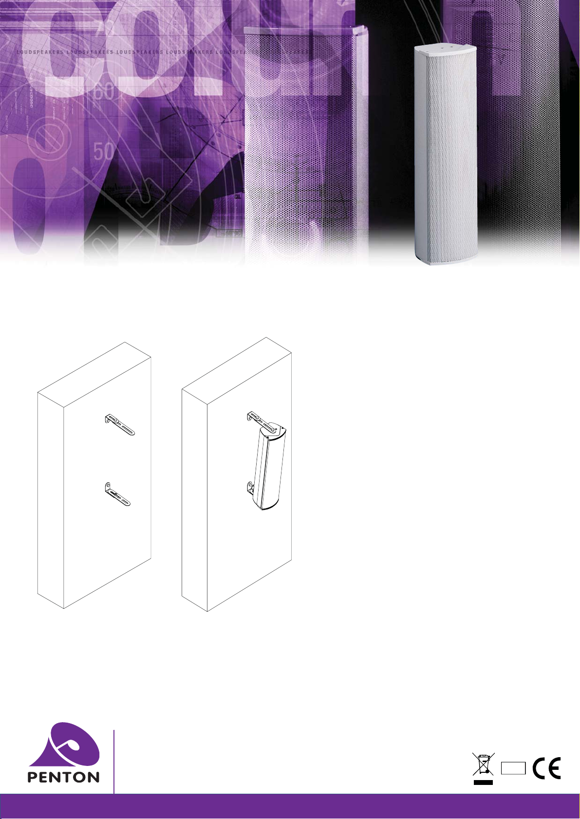
Mounting diagram:
Brackets and column
“L” Bracket
A
Extension Bracket
A
STEP 3
f
On terminating the wiring secure the cable gland tight into
the rear of the loudspeaker chamber.
STEP 4
f
Around the top lid you will observe a rubber gasket please
make sure that it is in place when relocating the lid to the
loudspeaker chamber to maintain its weather resistance.
STEP 5
f
Drill the mounting location holes for the unit in a vertical
plane (position “A” drawing below). Drill the outer bracket
holes 349 mm apart and the inner set 250 mm apart.
STEP 6
f
Mount the speaker in the required location as specified by
an acoustic engineer.
STEP 7
f
You may require tilting or distancing the column from the
mounting surface this can be done by extending the “L”
bracket with the supplied extension bracket in the hardware
kit.
Items to be found in the hardware kit:
Qty 2 “L” brackets
Qty 2 x extension brackets
Qty 4 x 10mm long hex head bolts (used to mount “L”
brackets)
Qty 2 x 20mm long hex head bolts (used to mount
extension brackets onto “L” brackets)
Qty 6 x washers (used with hex bolts above)
STEP 8
f
Before putting 100 volts through the unit it is advisable to
check the impedance of circuit.
A swivel mounting bracket is available for this unit see Penton
accessories.
Penton UK Ltd
Unit 2 Teville Industrials | Dominion Way | Worthing | West Sussex | BN14 8NW
T: +44 (0)1903 215315 | F: +44(0)1903 215415 | E: [email protected]
www.pentonuk.co.uk
NOVEMBER 2011
RoHS
 Loading...