

Page 1
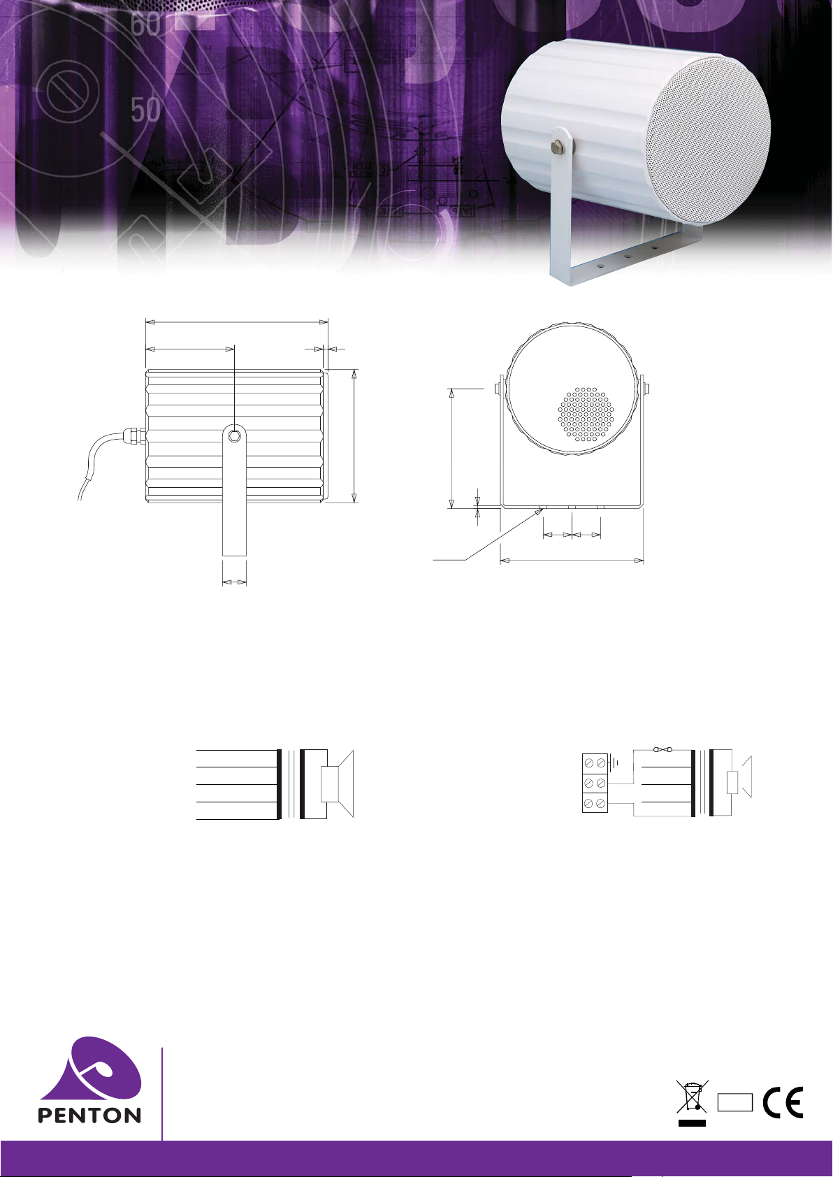
METAL SOUND PROJECTORS
CELL20/T
f
CELL20/TC
f
INSTALLATION INSTRUCTIONS
191
95 5
Back lid
ø140
Side View
25
STEP 1
f
Drill the mounting location holes for the loudspeaker in line with the “U” bracket (2 holes 30 millimetres apart) in the surface where the
loudspeaker is going to be located. It is not necessary to use the central mounting hole in the bracket unless the loudspeaker is used with a pole
mount clamp.
STEP 2
f
There are two versions of CELL’S, one is for general public address and the “C” version for voice alarm to comply with BS5839 part 8.
The connection for the CELL20/T are as follows:
CELL20/T Circuit diagram 100V Common CELL20/TC Circuit diagram 100V Common
Connection
through
cable tail
Important Note
Please ensure that the input cable is connected to the selected terminal inside the loudspeaker chamber and to no other connection, as the
unused transformer tappings must always be isolated from one another.
Example: CELL20/TC use the Black wire (common) and the red wire for 20 watt tapping.
Use the Black wire (common) and the Blue for 10 watt, etc.
STEP 3
f
Secure the cable gland tightly, ensuring that all the rubber washers are in place for the fixing screws. You will observe that around the inner
section of the chamber where the back lid was removed is a large rubber washer, please make sure that this is in-place when replacing lid.
STEP 4
f
Before connecting 100 volt line to the unit, it is advisable to check the impedance of the circuit.
Yellow
Orange
Blue
Red
2.5W
5W
10W
20W
unit: mm
.5
125
Ø
3 - 7
3
Ceramic
terminal
block
30 30
150
Front View
Thermal Fuse
2.5W
5W
10W
20W
Penton UK Ltd
Unit 2 Teville Industrials | Dominion Way | Worthing | West Sussex | BN14 8NW
T: +44 (0)1903 215315 | F: +44(0)1903 215415 | E: [email protected]
www.pentonuk.co.uk
NOVEMBER 2011
RoHS
 Loading...