

Page 1

Pentium
P55-IT
ISA PCI
with Onboard PCI IDE and Super Multi-I/O.
TRADEMARK
All products and company names are
trademarks or registered trademarks of
their respective holders.
MotherBoard
Page 2

Contents
Page
Chapter 1 - Introduction ................................................ 1-1
P55-IT Board Layout............................................................ 1-2
Chapter 2 - Hardware Design......................................... 2-1
Motherboard Layout .............................................................2-1
Connectors and Jumpers.......................................................2-2
System Memory configuration ..............................................2-4
Cache Memory configuration ...............................................2-5
Integrated PCI Bridge...........................................................2-6
Chapter 3 - Award BIOS ................................................ 3-1
Standard CMOS Setup .........................................................3-2
BIOS Features Setup ............................................................3-2
Chipset Features Setup .........................................................3-6
Power Management Setup ....................................................3-9
PCI Configuration Setup ......................................................3-11
Load Setup Defaults .............................................................3-13
Change password .................................................................3-13
IDE HDD Auto Detection.....................................................3-14
Save & Exit Setup ............................................................... 3-16
Exit Without Saving .............................................................3-16
Chapter 4 - Onboard Technical Information ................. 4-1
I/O & Memory Map ............................................................. 4-1
Time & DMA Channels Map ............................................... 4-2
Interrupt Map ...................................................................... 4-2
RTC & CMOS RAM Map .................................................... 4-3
Appendix A: Post Codes ...................................................... 4-4
Appendix B: I/O Connector .................................................. 4-8
Page 3

NOTE :
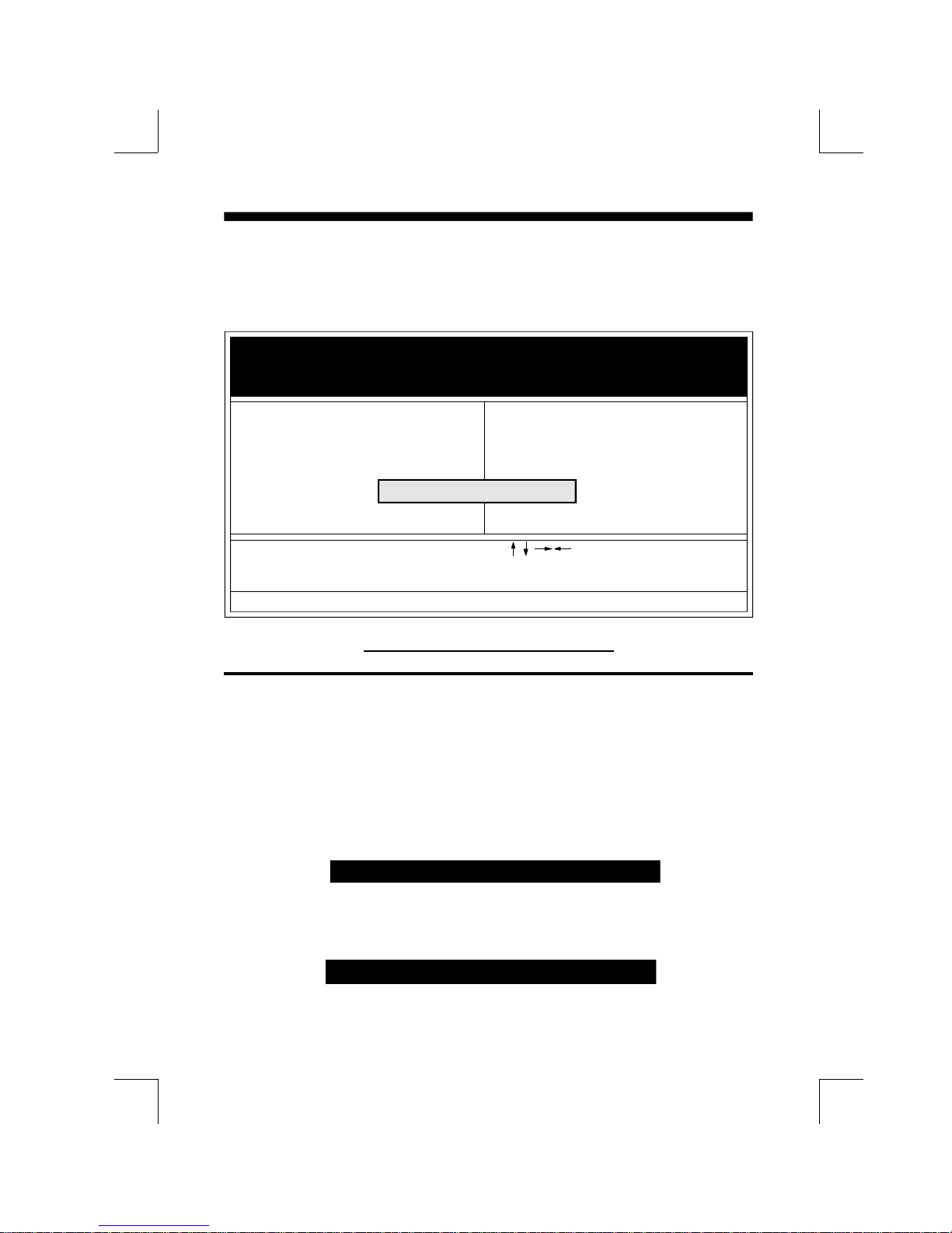
The " LOAD SETUP DEFAULTS " function loads the system default data directly
from ROM and initialize associated hardware properly. This function will be necessary
when you accept this motherboard, or the system CMOS data is corrupted.
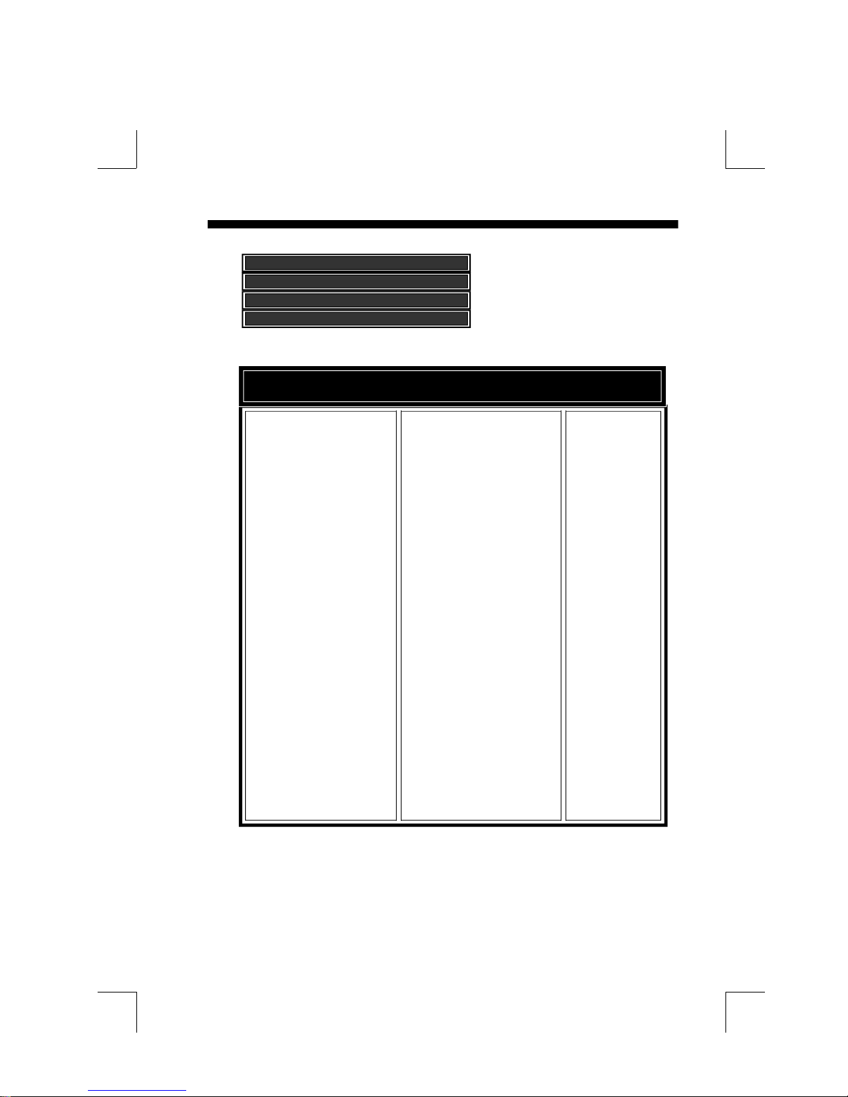
ROM PCI/ISA BIOS (2A59CPA9)
CMOS SETUP UTILITY
AWARD SOFTWARE, INC.
STANDARD CMOS SETUP PASSWORD SETTING
BIOS FEATURES SETUP IDE HDD AUTO DETECTION
CHIPSET FEATURES SETUP SAVE & EXIT SETUP
POWER MANAGEMENT VING
PCI CONFIGURATION SETUP
LOAD SETUP DEFAULT
ESC: QUIT :SELECT ITEM
F10:Save & Exit Setup (Shift)F2:Change Color
Load SETUP Default (Y/N)? Y
Time, Date, Hard Disk Type....
LOAD SETUP DEFAULT
Page 4

Introduction 1-1
Chapter 1
Introduction
The P55-IT motherboard is a high performance system hardware based
on Intel Pentium processor and is equipped with four PCI slots, four
standard ISA slots, Super Multi-I/O controller and dual ports PCI-IDE
connectors for the future expansion. The hardware dimension is 220mm x
280mm with four layer design technology.
Specification
Intel Pentium Processor operating at 50/75, 60/90, 66/100, 60/120, 66/
133, 60/150, 66/166 MHz and P55C/P55CT with 321 ZIF socket 7,
VRM and scalability to accept faster Pentium Processors in the feature.
Supports up to 128 MegaBytes DRAM(minimum of 8 MB) on board(72
Pins SIMM x 4), and BIOS auto DRAM/EDO RAM configuration.(Refer
to Chapter 2-3 System Memory Configuration)
Supports both Fast Page DRAM or EDO DRAM SIMM.
INTEL Triton 82430FX PCIset chipset.
Supports Burst/Pipelined burst synchronous ( The COAST solution ) and
asynchronous L2 Write Back Cache. The cache memory combination
could be 256KB/512KB (32KB*8 or 64KB*8 SRAM respectively).
Support four 16 bits ISA slots, four 32 bits PCI slots, and provides two
independent high performance PCI IDE interface capable of supporting
PIO Mode 3 and Mode 4 devices. The P55-IT supports four PCI Bus
Masters and a jumperless PCI INT# control scheme which reduces
configuration confusion when plug in PCI I/O controller card(s).
Supports AT API (e.g. CD-ROM) devices on both IDE interface.
Supports 1 floppy port(up to 2.88 MB), 1 parallel port (EPP,ECP port),
and 2 serial port (16550 Fast UART compatible).
Supports a PS/2 style mouse and standard AT style keyboard connectors.
Support Award Plug & Play BIOS . The BIOS is stored in Flash EPROM
form. It provides better upgradeability for the system.
Supports CPU Hardware sleep and SMM (System Management Mode).
Supports hardware Turbo switch as well as BIOS hot key switching.
P55-IT utilizes Lithium battery which provides environmental protection
and longer life time.
Page 5
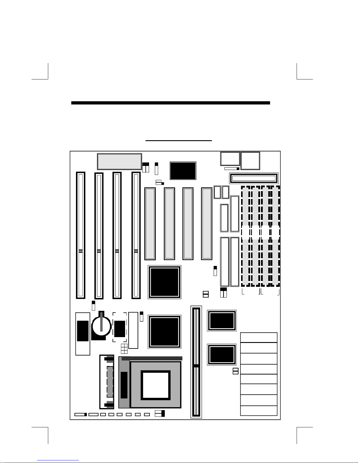
1-2 P55-IT
Keyboard BIOS
P55-IT Layout
1
1
SMC
37C665
1
JP15
J24
J25
JP12
J10
1 1
PS/2
MOUSE
5
COM2
COM1
K/B
CONN.
1
Power Conn.
1
1
JP6
<
<
BIOS
GND
+12V
GND
VRM Socket
SPK. RESET
KEYLOCK
J1 J2 J3 J4 J5 J6 JP5 JP14
TAG SRAM (U24)
RTC
J7
Socket 7
G-LED HD-LED SLEEPTB-SW TB-LED
JP6
1
+++
PCI#4
PCI#3
Intel
82371
Intel
82437
JP9
JP7
1
Figure 1-1
PCI#2
JP1
JPS1
JPS2
81
160 80
1
SRAM Module
1
PRINTER
PCI#1
1 2 1 2
IDE 2 CONN.
1
1
JP21JP3
82438
82438
J23
FDD CONN.
M 1
IDE 1 CONN.
39 40
BANK0 BANK1
82438
U28
U29
U32
U33
U34
U37
U41
U42
M 2
M 4
M 3
<
<
82438
<
<
<
<
<
<
Page 6

Hardware Design 2-1
Chapter 2
Hardware design
2-1 Motherboard Layout
The P55-IT is designed with Intel Triton 82430FX PCIset chipset which is
developed by INTEL Corporation to fully support Intel Pentium PCI/ISA system.
The Intel "Triton" 82430FX PCIset chipset prpovides increased integration and
improved performance designs. The "Triton" chipset provides an integrated IDE
controller with two high performance IDE interfaces for up to four IDE devices
(hard devices, CD-ROM device, etc). The SMC (STANDARD MICROSYSTEMS
CORPORATION) FDC37C665GT Super I/O controller provides the standard PC
I/O function: floppy interface (up to 2.88 MB), two 16 Byte FIFO serial ports and
EPP/ECP capable parallel port. The P55-IT layout is shown in previous page (left
page) for user's reference. Care must be taken when inserting memory modules,
inserting Intel P54C/P55C/P55CT processor, inserting VRM( Voltage Regulator
Module) or even plugging PCI card into associated slots to avoid damaging any
circuits or sockets on board. A cooling fan is strongly recommended when installing P54C/P55C processor due to possible overheat.
The P55-IT supports minimum of 8MB of System Memory and maximum of
128MB while L2 Cache can be 256KB/512KB synchronous (The COAST "CacheOn-A-STick" solution ) or asynchronous SRAM to increase system performance.(
refer to Page 2-5 Cache Memory Configuration for the details.)
The P55-IT support standard Fast Page or EDO (Extended Data Out or Hyper
Page Mode) DRAM. The EDO DRAM is designed to improve the DRAM read
performance (When L2 Cache is asynchronous SRAM and not installed). The
P55-IT provides four 72-pins SIMM sites for memory expansion. The socket
support 1M x 32(4MB), 2M x 32(8MB), 4M x 32(16MB), and 8M x 32(32MB)
single-sided or double-sided SIMM modules. The memory timing requires 70 nS
Fast page devices or 60 nS EDO DRAM. Memory parity generation and checking
is not supported. (DRAM Modules may be parity[x 36] or non-parity[x 32].
The P55-IT supports Onboard two PCI IDE connectors, and detects IDE
harddisk type by BIOS utility automatic.
The P55-IT supports Award Plug & Play BIOS for the ISA and PCI cards. The
BIOS can be located in Flash EPROM. The advantage of having Flash EPROM is
much easier to replace BIOS code if necessary.
Page 7
2-2 P55-IT
2-2 Connectors and Jumpers
This section describes all of the connectors and jumpers equipped in the
motherboard. Please refer to Figure 1-1 for actual location of each connector and
jumper.
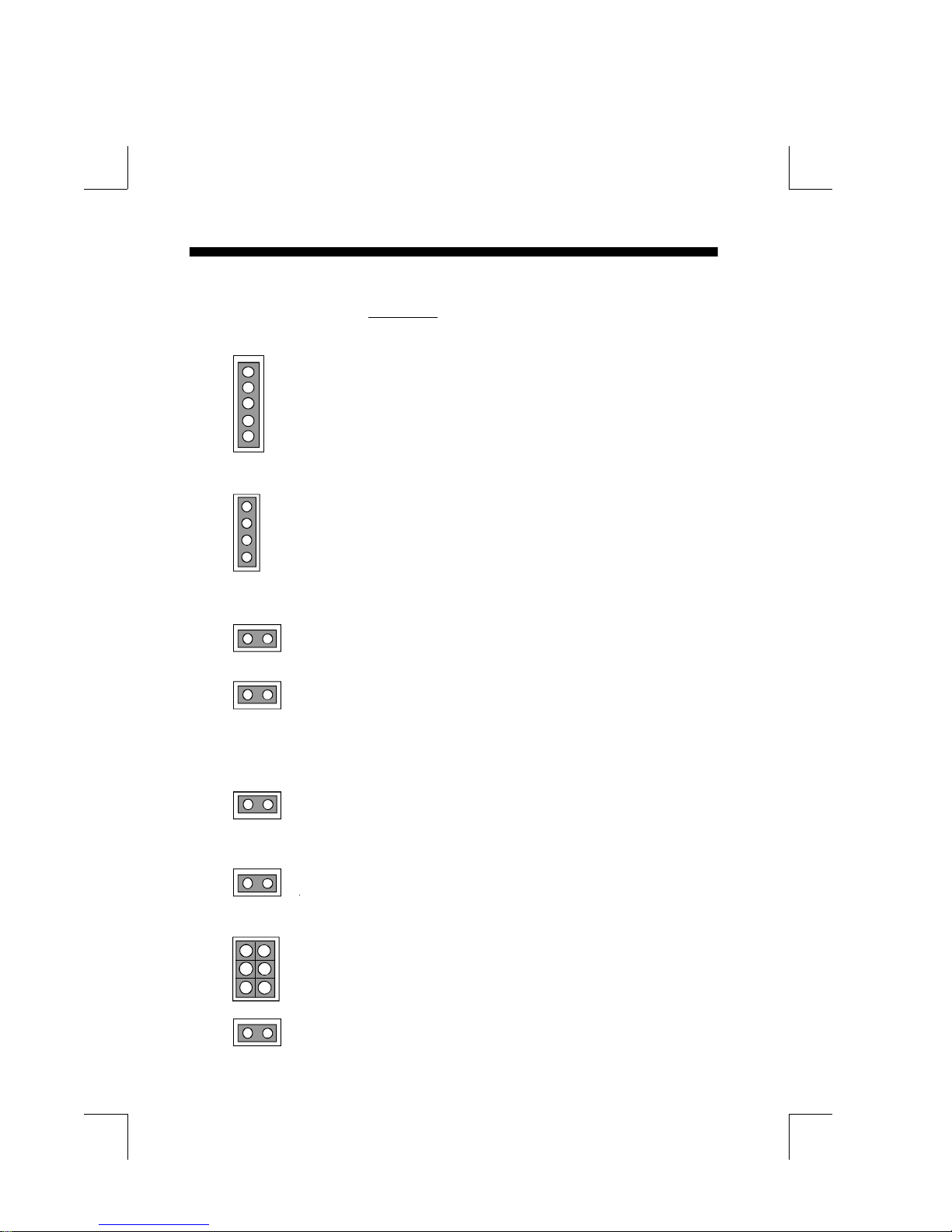
J1 KeyLock - Keyboard lock switch & Power LED connector.
1
1.Power LED(+)
2.N/C
3.GND
4.Keylock
5
5.GND
J2 Speaker - connect to the system's speaker for beeping.
1
1. Speaker
2. N/C
3. GND
4
4. GND
J3 Reset - Close to restart system.
J4 Turbo Switch : Open for slower speed while Close for
higher speed. A BIOS hot key <CTRL><ALT><+>
also brings system to a higher speed while<CTRL>
<ALT><-> set system to a slower speed(When J4 is open.).
J5 Turbo LED indicator - LED ON when higher speed is
selected.
+
J6 Power Saving LED indicator - LED ON when system is in
any Saving mode.
+
J7 The Power supply of the CPU cooling fan
1
3
5
2
1,2 GND
4
3,4 +12V
6
5,6 GND
JP5 IDE LED indicator - LED ON when Onboard PCI IDE
Harddisks activites.
+
Page 8
Hardware Design 2-3
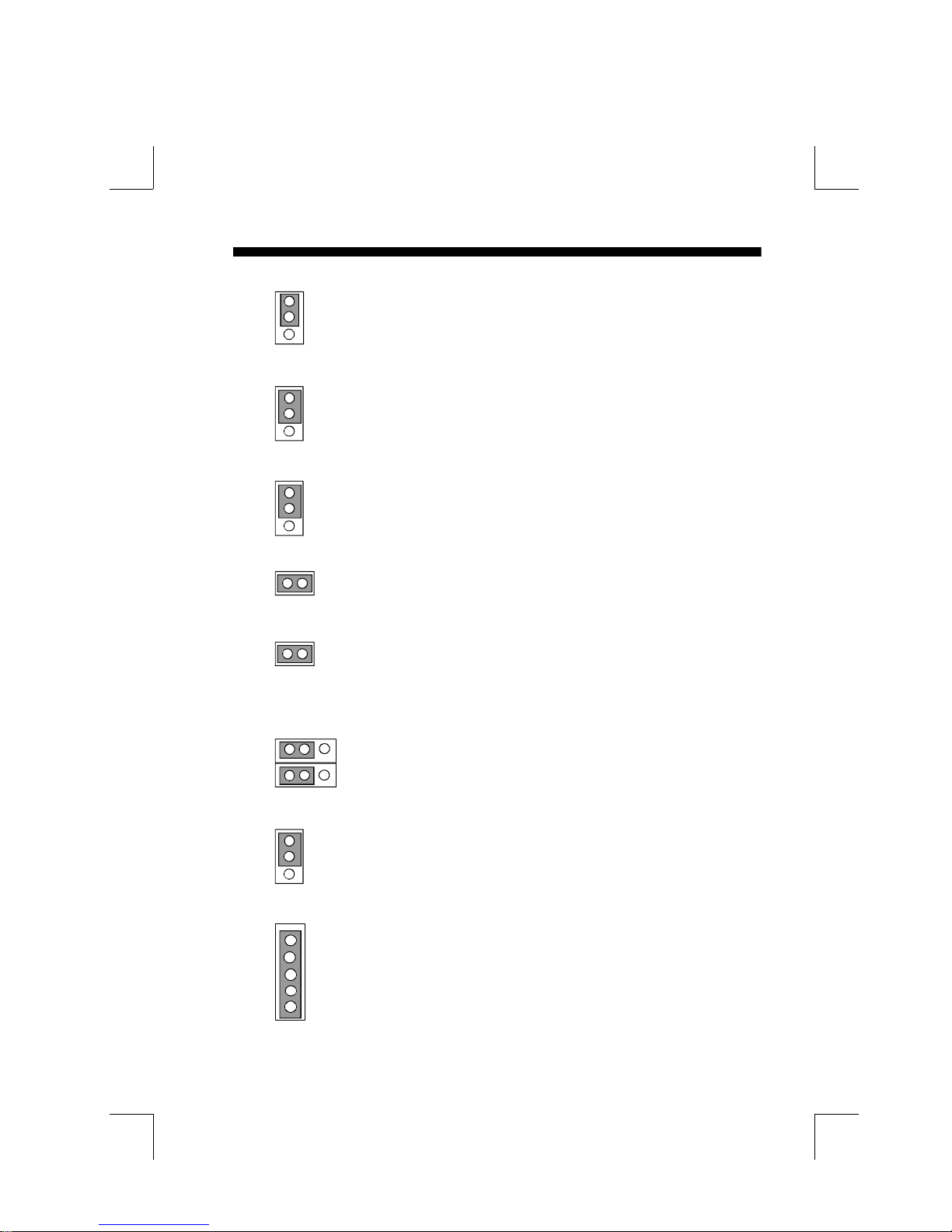
JP1 CPU Install : 1-2 for Intel Pentium P54C, P54CS CPU (Default).
1
2-3 for Intel Pentium P55C/P55CT CPU.
3
JP2 Onboard IDE 1: 1-2 for Primary IDE 1 Interrupt IRQ14.
1
2-3 for None
3
JP3 Onboard IDE 2 : 1-2 for Secondary IDE 2 Interrupt IRQ15.
1
2-3 for None
3
JP14 Sleep/Resume switch : Close to enter sleep mode.
A keystrobe or mouse movement (mouse driver exists). The system
will instantly "wake up".
J24 Onboard SMC's chip select :
Open: Normal operation.(Default)
Close: Disable the Onboard SMC chip.
1 2 3
JP15 Keyboard Operation Clock Select :
1-2 The clock rate is depend on the system AT CLOCK
( J25 ). (Default)
2-3 The clock rate is 12MHz.
JP6 EPROM BIOS Select : 1-2 for 5V Flash EPROM (Default)
1
while 2-3 for 12V Flash EPROM.
3
J10 PS/2 MOUSE CONNECTOR:
1
5
1.RED wire
2.BLUE wire
3.GREEN wire
4.NC
5.YELLOW wire
Page 9
2-4 P55-IT
JPS1
JPS2
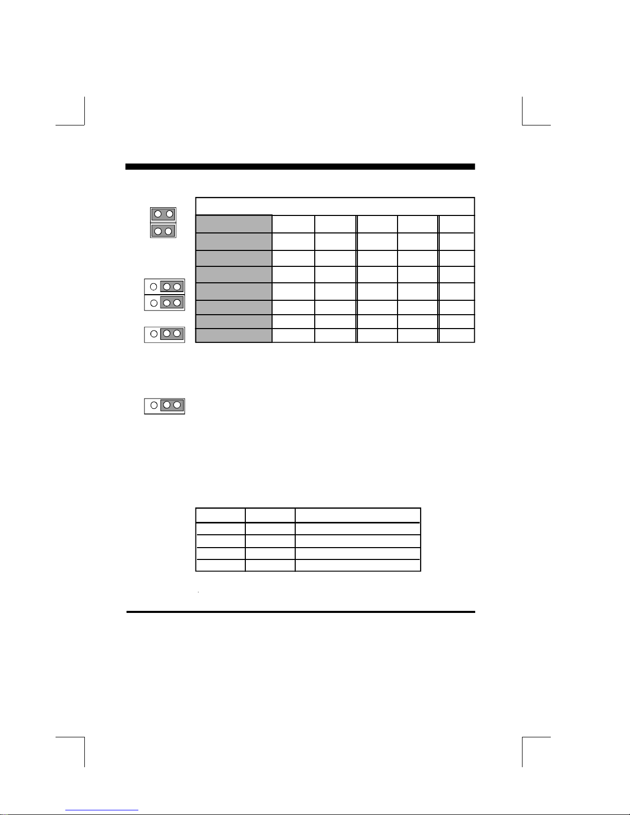
50/75 MHz OPEN OPEN 2-3 2-3 1-2
66/100 MHz CLOSE CLOSE 2-3 2-3 2-3
60/120 MHz CLOSE OPEN 1-2 2-3 2-3
66/133 MHz CLOSE CLOSE 1-2 2-3 2-3
60/150 MHz CLOSE OPEN 1-2 1-2 2-3
1 2 3
JP7
JP9
1 2 3
J25
1 2 3
J25
If system is operating at 66/100 MHz, than PCICLK is 33Mhz.
Clock/CPU Op. JPS1 JPS2 JP7 JP9 J25
60/90 MHz CLOSE OPEN 2-3 2-3 2-3
66/166 MHz CLOSE CLOSE 1-2 1-2 2-3
* Clock is System Clock.
* CPU OP. is CPU operation at 75, 90, 100 MHz, etc.
System AT BUS CLOCK Select:
2-3 ATCLK is devided PCICLK* by 4.(Default)
* PCICLK = System Clock / 2
1-2 ATCLK is devided PCICLK* by 3.
Clock chip is IMI SC484
JP7 JP9 CLOCK Chip Frequency.
2-3 2-3 x ( 1.5 ) (Default)
1-2 2-3 x ( 2 )
2-3 1-2 x ( 3 )
1-2 1-2 x ( 2.5 )
* The JP7 and JP9 be used to setting the faster Pentium Processor in the feature.
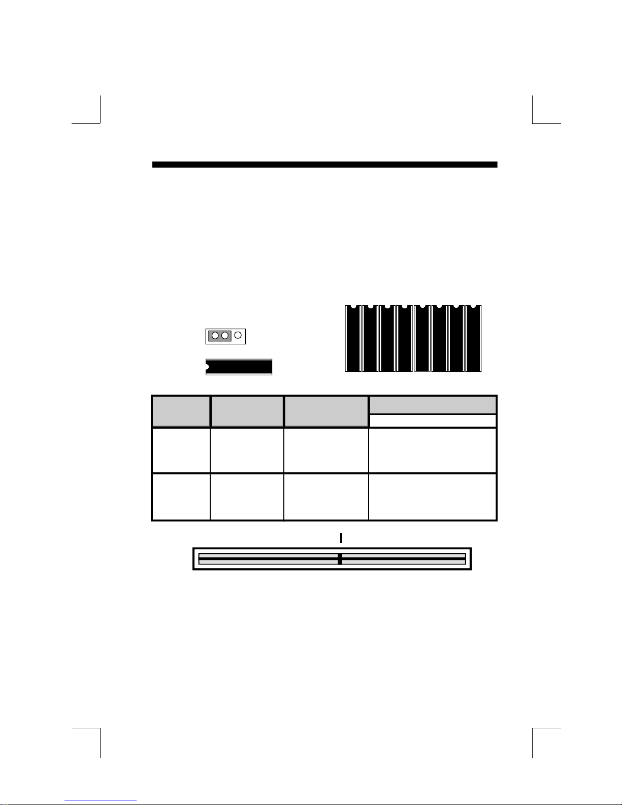
2-3 System Memory Configuration
The P55-IT supports different type of settings for the system memory. There is no
jumper nor connector needed for memory configuration. Following figures provides
all possible memory cominations.
Page 10
Hardware Design 2-5
2-4 Cache Memory Configuration
The second level (L2) of cache is installed in the motherboard to increase the
system performance. The P55-IT supports different type of combinations for the
cache installation. The COAST (Cache-On-A-STick. The cache modules has a
TAG SRAM.) solution provides Onboard flexibility, allowing Onboard to accommodate 256KB and 512KB asynchronous, burst and piplined burst SRAM modules.
Jumper JP10 settings is used to Onboard's DIP asynchronous SRAM for differential
such combinations. Please refer to following configurations for the details.
JP10
1 2 3
U28
U29
U32
U33
U34
U37
U41
U42
U24
TAG SRAM
DATA SRAM
CACHE TAG SRAM Data SRAM Jumper Setting
Size (U24) Install JP10
U18
8K8 x 1 or 32K8 x 8
256KB 16K8 x 1 or U28,29,32,33 1-2
32K8 x 1 U34,37,41,42
16K8 x 1 or 64K8 x 8
512KB 32K8 x 1 U28,29,32,33 2-3
U34,37,41,42
160
80
Note: When you have a cache module to plug into a 160-pin daul
KEY
v
Burst/Pipelined burst/Asynchronous SRAM Modules
readout connector. You must make sure that cache modules has a
TAG SRAM(Care must be taken when you inserting the modules. If
you can't sure whether that is a COAST solution modules or not.
Please contact the modules supplier to avoid burned-out and
damaging any modules circuits. ) and take off the Onboard's DIP
asynchronous DATA and TAG SRAM. The BIOS can auto-detect the
type and size of the SRAM modules on display System Configurations before the system boots Operating System.
81
1
Page 11

2-6 P55-IT
2-5 Integrated PCI Bridge
The P55-IT utilizes Intel's Triton 82430 PCIset chipset to support Intel Pentium
P54C/P54CS/P55C/P55CT Processor PCI/ISA system. The Intel Triton 82430FX
PCIset chipset consists of the 82437FX Triton system controller (TSC), two
82438FX Triton Data Path (TDP) devices, and one 82371FB PCI ISA/IDE Accelerator (PIIX) bridge chip. It provides an interface which translates CPU cycle into
PCI bus cycle, and PCI burst read/write capability. In addition, it provides high
performance PCI arbitor to support four PCI Masters, Rotating Priority Mechanism, and Hidden Arbitration Scheme Minimizes Arbitration Overhead.
There are four interrupts in each PCI slot : INTA#, INTB#, INTC#, and INTD#.
Since the P55-IT adapts the PCI auto-configuration with the system BIOS Setup
utility. When the system is turned on after adding a PCI add-in card, the BIOS
automatically configure interrupts, DMA channels, I/O space, and other
paramaters. You do not have to configures jumpers or worry potential resource
conflicts. Because PCI cards use the same interrupt resource as ISA cards, you must
specify the interrupt used by ISA add-in cards in the BIOS Setup utility.
If however, a "Legacy card" (such as plug paddle card and cable into the ISA slot.)
is plugged in the system, modification in the ROM SETUP UTILITY become
necessary. First, enter PCI CONFIGURATION SETUP utility from ROM
SETUP UTILITY main menu to set the "PCI IDE IRQ MAP TO : ISA".
Second, you must be enter CHIPSET FEATURES SETUP UTILITY from ROM
SETUP UTILITY main menu and set the "Onboard Primary PCI IDE: Disabled
and Onboard Secondary PCI IDE: Disabled." When you plugged the PCI/ISA
IDE card into the system. You will Disabled Onboard Primary and Secondary
PCI IDE from CHIPSET FEATURES SETUP UTILITY too.
Some "Legacy card" ( no paddle card and cable.) you can set the system interrupt
request (IRQ) on the "Legacy card" (refer to user's manual of the card) to a proper
system IRQ level (in general, card's Primary assigned to INTA and Secondary
assigned to INTB). If the card is plugged into slot 1(marked PCI#1), you can not
use second slot (marked PCI#2) because the Secondary INT signal takes INTB
from the slot (refer to Page 3-12 for circuit diagram). The user then enter PCI
CONFIGURATION SETUP utility from ROM SETUP UTILITY main menu
and set the "PCI IDE IRQ MAP TO : PCI-Slot 1" (depend on the slot # where the
Legacy card is plugged).
.
Page 12
P55-IT 2-4-1
M1
M2
M3
M4
BANK0 Single Side DRAM
BANK0,1 Dual Side DRAM
>
BANK1 Single Side DRAM
BANK2,3 Dual Side DRAM
>
M1,M2(BANK 0) M3,M4( BANK 1) Total Size
1M x 32 (4 MB) Empty 8MB
1M x 32 (4 MB) 1M x 32 (4 MB) 16MB
1M x 32 (4 MB) 2M x 32 (8 MB) 24MB
1M x 32 (4 MB) 4M x 32 (16 MB) 40MB
1M x 32 (4 MB) 8M x 32 (32 MB) 72MB
2M x 32 (8 MB) Empty 16MB
2M x 32 (8 MB) 1M x 32 (4 MB) 24MB
2M x 32 (8 MB) 2M x 32 (8 MB) 32MB
2M x 32 (8 MB) 4M x 32 (16 MB) 48MB
2M x 32 (8 MB) 8M x 32 (32 MB) 80MB
4M x 32 (16 MB) Empty 32MB
4M x 32 (16 MB) 1M x 32 (4 MB) 40MB
4M x 32 (16 MB) 2M x 32 (8 MB) 48MB
4M x 32 (16 MB) 4M x 32 (16 MB) 64MB
4M x 32 (16 MB) 8M x 32 (32 MB) 96MB
8M x 32 (32 MB) Empty 64MB
8M x 32 (32 MB) 1M x 32 (4 MB) 72MB
8M x 32 (32 MB) 2M x 32 (8 MB) 80MB
8M x 32 (32 MB) 4M x 32 (16 MB) 96MB
8M x 32 (32 MB) 8M x 32 (32 MB) 128MB
NOTE : 1. P55-IT support both Fast Page DRAM or EDO
DRAM SIMMs, but they cannot be mixed within
the same memory bank.
4. "BANK' = 64 Bit = M1, M2 = M3, M4
2. SIMMs may be parrity(x 36) or non parity (x 32).
3. The 70nS Fast Page Mode or 60nS EDO DRAM is
necessary.
Page 13

AWARD BIOS 3-1
CHAPTER 3
AWARD BIOS SETUP
Award's ROM BIOS provides a built-in Setup program which allows user modify the
basic system configuration and hardware parameters. The modified data will be stored
in a battery-backed CMOS RAM so data will be retained even when the power is turned
off. In general, the information saved in the CMOS RAM stay unchanged unless there
is configuration change in the system, such as hard drive replacement or new
equipment is installed.
It is possible that CMOS had a battery failure which cause data lose in CMOS_RAM.
If so, re_enter system configuration parameters become necessary.
To enter Setup Propgram
Power on the computer and press <Del> key immediately will bring you into BIOS
CMOS SETUP UTILITY.
ROM PCI/ISA BIOS (2A59CPA9)
CMOS SETUP UTILITY
AWARD SOFTWARE, INC.
STANDARD CMOS SETUP PASSWORD SETTING
BIOS FEATURES SETUP IDE HDD AUTO DETECTION
CHIPSET FEATURES SETUP SAVE & EXIT SETUP
POWER MANAGEMENT SETUP EXIT WITHOUT SAVING
PCI CONFIGURATION SETUP
LOAD SETUP DEFAULTS
ESC: QUIT :SELECT ITEM
F10:Save & Exit Setup (Shift)F2:Change Color
Time, Date, Hard Disk Type....
Figure 3-1 CMOS SETUP UTILITY
The menu displays all the major selection items and allow user to select any one of
shown item. The selection is made by moving cursor (press any direction key ) to
the item and press 'Enter' key. An on_line help message is displayed at the bottom
of the screen as cursor is moving to various items which provides user better
understanding of each function. When a selection is made, the menu of selected
item will appear so the user can modify associated configuration parameters.
Page 14

3-2 CHAPTER 3
3-1 STANDARD CMOS SETUP
Choose "STANDARD CMOS SETUP" in the CMOS SETUP UTILITY Menu
(Fig.3-1). The STANDARD CMOS SETUP allows user to configure system setting
such as current date and time, type of hard disk drive installed in the system, floppy drive
type, and the type of display monitor. Memory size is auto_detected by the BIOS and
displayed for your reference. When a field is highlighted (direction keys to move cursor
and <Enter> key to select), the entries in the field will be changed by pressing <PgDn>
or <PgUp> keys or user can enter new data directly from the keyboard.
ROM PCI/ISA BIOS (2A59CPA9)
STANDARD CMOS SETUP
AWARD SOFTWARE, INC.
Date (mm:dd:yy) :Sat, Jul 01 1995
Time (hh:mm:ss) :8:30:50
Daylight Saving :Disabled
HARD DISKS TYPE SIZE CYLS HEAD PRECOMP LANDZONE SECTORS MODE
Primary Master : Auto 0 0 0 0 0 0 LBA
Primary Slave : Auto 0 0 0 0 0 0 Normal
Secondary Master : Auto 0 0 0 0 0 0 Normal
Secondary Slave : Auto 0 0 0 0 0 0 Normal
Drive A : 1.2M,5.25 in.
Drive B : None
Video : EGA/VGA
Halt On : All Errors
Base Memory : 640K
Extended Memory : 15360K
Other Memory : 384K
Total Memory : 16384K
ESC : QUIT :SELECT ITEM PU/PD/+/-:Modify
F1 : Help (Shift)F2 :Change Color F3:Toggle Calender
Figure 3-2 STANDARD CMOS SETUP
NOTE: If hard disk Primary Master/Slave and Secondary Master/Slave were used Auto,
than the hard disk size and model will be auto-detect on display during POST.
NOTE: The "Halt On :" field is to determine when to halt the system by the BIOS if error
occurred during POST.
3-2 BIOS FEATURES SETUP
Select the "BIOS FEATURES SETUP " option in the CMOS SETUP UTILITY menu
allows user to change system related parameters in the displayed menu. This menu
shows all of the manufacturer's default values of P55-IT. Again, user can move the
cursor by pressing direction keys and <PgDn> or <PgUp> keys to modify the
parameters. Pressing [F1] key to display help message of the selected item.
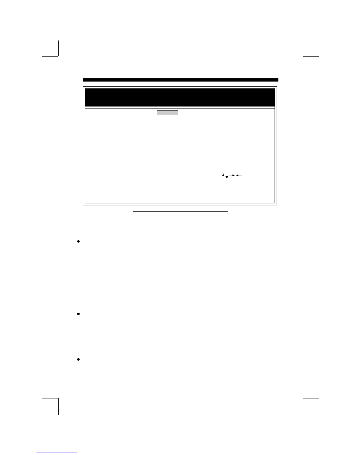
This setup program also provide 2 convinent ways to load the default parameter data
from BIOS[F6] or CMOS[F7] area if shown data is corrupted. This provide the system
a capability to recover from any possible error.
Page 15
AWARD BIOS 3-3
ROM PCI/ISA BIOS (2A59CPA9)
BIOS FEATURES SETUP
AWARD SOFTWARE, INC.
Virus Warning : Disabled Video BIOS Shadow : Enabled
CPU Internal Cache : Enabled C8000-CBFFF Shadow : Disabled
External Cache : Enabled CC000-CFFFF Shadow : Disabled
Quick Power On Self Test : Enabled D0000-D3FFF Shadow : Disabled
Boot Sequence : A,C D4000-D7FFF Shadow : Disabled
Swap Floppy Drive : Disabled D8000-DBFFF Shadow : Disabled
Boot Up Floppy Seek : Enabled DC000-DFFFF Shadow : Disabled
Boot Up NumLock Status : On
Boot UP System Speed : Low
Gate A20 option : Fast
Typematic Rate Setting : Disabled
Typematic Rate (Chars/Sec) : 6
Type matic Delay (Msec) : 250
Security Option : Setup
Esc : Quit : Select Item
F1 : Help PU/PD/+/- : Modify
F5 : Old Values (Shift)F2 : Color
F6 : Load BIOS Defaults
F7 : Load Setup Defaults
Figure 3-3 BIOS FEATURES SETUP
Note: The Security Option contians "setup" and "system". The "setup" indicates
that the password setting is for CMOS only while the " system" indicates the
password setting is for both CMOS and system boot up procedure.
Virus Warning: This category flashes on the screen. During and after the system
boots up, any attempt to write to the boot sector or partition table of the hard disk
drive will halt the system and the following error message will appear, in the mean
time, you can run an anti-virus program to locate the problem. Default value is
Disabled
Enabled : Activates automatically when th e system boots up causing a warning
message to appear when anything attempts to access the boot sector or
hard disk partition table.
Disabled: No warning message to appear when anything attempts to access the boot
sector or hard disk partition table.
CPU Internal Cache / External Cache:These two categories speed up memory
access. However, it depends on CPU/chipset design. The default value is Enable.
If your CPU without Internal Cache then this item "CPU Internal Cache" will not
be show.
Enabled: Enable cache.
Disable : Disable cache.
Quick Power On Self Test:This category speeds up Power On Self Test (POST)
after you power on the computer. If it is set to Enable, BIOS will shorten or skip
some check items during POST.
Enabled : Enable quick POST.
Disabled: Normal POST.
Page 16

3-4 CHAPTER 3
Boot Sequence: This category determines which drive computer searches first for
the DOS(Disk Operating System). Default value is A,C.
A,C : System will first search for floppy disk drive then hard disk drive.
C,A : System will first search for hard disk drive then floppy disk drive.
Swap Floppy Drive: The swap floppy drive. Default value is Disabled.
Enabled : Floppy A & B will be swapped under the DOS.
Disabled: Floppy A & B will be not swap.
Boot Up Floppy Seek: During POST,BIOS will determine if the floppy disk drive
installed is 40 or 80 tracks. 360K type is 40 tracks while 760K, 1.2M and 1.44M are
all 80 tracks. The default value is Enabled.
Enabled : BIOS searches for floppy disk drive to determine if it is 40 or 80 tracks,
Note that BIOS can not tell from 720K, 1.2M or 1.44M drive type as
they are all 80 tracks.
Disabled: BIOS will not search for the type of floppy disk drive by track number.
Note that there will not be any warning message if the drive installed
is 360K.
Boot Up NumLock Status: The default value is On.
On : Keypad is number keys.
Off : Keypad is arrow keys.
Boot UP System Speed: It selects the default system speed, the speed that the
system will run at immediately after power up.
High: Set the speed to high.
Low : Set the speed to low.
NOTE: The board default value is LOW in the field. Boot the system to controller
turbo or De-turbo by Onboard J4 (Turbo Switch).
Gate A20 Option: The default value is Fast.
Normal: The A20 signal is controlled by keyboard controller or chipset hardware.
Fast : Default : Fast.The A20 signal is controlled by Port 92 or chipset specific
method.
Typematic Rate Setting: This determines the typematic rate.
Enabled : Enable typematic rate and typematic delay programming.
Disabled: Disable typematic rate and typematic delay programming. The system
BIOS will use default value of this 2 items and the default is controlled
by keyboard.
Typematic Rate(Chars/Sec):
6 : 6 characters per second. 8 : 8 characters per second.
10: 10 characters per second. 12: 12 characters per second.
15: 15 characters per second. 20: 20 characters per second.
24: 24 characters per second. 30: 30 characters per second.
Page 17

AWARD BIOS 3-5
Typematic Delay(Msec): When holding a key, the time between the first and
second character displayed.
250 : 250msec.
500 : 500 msec.
750 : 750 msec.
1000: 1000 msec.
Security Option: This category allows you to limit access to the system and Setup,
or just to Setup. The default value is Setup.
System: The system will not boot and access to Setup will be denied if the correct
password is not entered at the prompt.
Setup : The system will boot, but access to Setup will be denied if the incorrect
password is not entered at the prompt.
NOTE: To disable security, select PASSWORD SETTING at Main Menu and
then you will be asked to enter password. Do not type anything and just press
<Enter>, it will disable security. Once the security is disabled, the system will
boot and you can enter Setup freely.
Video BIOS Shadow: It determines whether video BIOS will be copied to RAM,
however, it is optional from chipset design. Video Shadow will increase the video
speed.
Enabled : Video shadow is enabled.
Disabled: Video shadow is disabled.
C8000 - CBFFF Shadow :
CC000 - CFFFF Shadow:
D0000 - D3FFF Shadow:
D4000 - D7FFF Shadow:
D8000 - DBFFF Shadow:
DC000 - DFFFF Shadow:
These categories determine whether optional ROM will be copied to RAM by 16K
byte or 32K byte per/unit and the size depends on chipset.
Enabled : Optional shadow is enabled.
Disabled: Optional shadow is disabled.
Page 18

3-6 CHAPTER 3
3-3 CHIPSET FEATURES SETUP
Choose the "CHIPSET FEATURES SETUP" in the CMOS SETUP UTILITY
menu to display following menu.
ROM PCI/ISA BIOS (2A59CPA9)
CHIPSET FEATURES SETUP
AWARD SOFTWARE, INC.
PCI Concurrency : Disable
PCI Streaming : Disabled
DRAM Timing : 60ns PCI Bursting : Enabled
Onboard FDC Controller : Enabled
System BIOS Cacheable : Disabled Onboard Serial Port 2 : COM 2
Video BIOS Cachlable : Enabled Onboard Parallel Port : 278H
8 Bit I/O Recovery Time : 1 Parallel Port Mode : ECP + EPP
16 Bit I/O Recovery Time : 1 ECP Mode DMA Select : DMA3
Memory Hole At 15M-16M : Disabled
IDE HDD Block Mode : Enabled
IDE Primary Master PIO : Auto
IDE Primary Slave PIO : Auto ESC : Quit : Select Item
IDE Secondary Master PIO : Auto F1 : Help PU/PD/+/- : Modify
IDE Secondary Slave PIO : Auto F5 : Old Valume (Shift )F2 : Color
Onboard Primary PCI IDE : Enabled F6 : Load BIOS Defaults
Onboard Secondary PCI IDE : Enabled F7 : Load Setup Defaults
PCI Slot IDE 2nd Channel : Enabled
Onboard Serial Port 1 : COM 1
Figure 3-4 CHIPSET FEATURES SETUP
Note:
If you don't use the Onboard IDE connector, than use On-card
(PCI or ISA card) IDE connector. You will set Onboard Primary
IDE: Disabled and Onboard Secondary IDE: Disabled from
CHIPSET FEATURES SETUP UTILITY.
The Onboard PCI IDE cable should be equal to or less than
18 inches (45 cm.).
DRAM Timing: The default value is 60ns.
60ns : 2 (faster) Burst Wait State, for 60~70ns Fast Page Mode/EDO DRAM.
70ns : 3 (slower) Burst Wait State, for 70ns Fast Page Mode/EDO DRAM.
Video BIOS Cacheable: The default value is Enabled.
Enabled : This field Enabled the Video BIOS Cacheable to speed up the VGA
Performance.
Disabled: Disabled the Video BIOS Cacheable function.
8/16 Bit I/O Recovery Time: The default value is 1.
8 Bit I/O Recovery Time: This field defines the recovery time from 1 to 8 for 8-bit
I/O.
16 Bit I/O Recovery Time: To define the recovery time from 1 to 4 for 16-bit I/O.
Page 19

AWARD BIOS 3-7
Memory Hole At 15M-16M: The default value is Disabled.
Disabled: Normal Setting.
Enabled : This field enableds the main memory (15~16MB) remap to ISA BUS.
IDE HDD Block Mode: The default value is Enabled.
Enabled : Enabled IDE HDD Block Mode. The HDD transfer rate is better than
Disable.
Disabled: Disable IDE HDD Block Mode.
IDE Primary Master PIO: The default value is Auto.
Auto : BIOS will automatically detect the Onboard Primary Master PCI IDE
HDD Accessing mode.
Mode0~4: Manually set the IDE Accessing mode.
IDE Primary Slave PIO: The default value is Auto.
Auto : BIOS will automatically detect the Onboard Primary Slave PCI IDE
HDD Accessing mode.
Mode0~4: Manually set the IDE Accessing mode.
IDE Secondary Master PIO: The default value is Auto.
Auto : BIOS will automatically detect the Onboard Secondary Master PCI IDE
HDD Accessing mode.
Mode0~4: Manually set the IDE Accessing mode.
IDE Secondary Slave PIO: The default value is
Auto : BIOS will automatically detect the Onboard Secondary Slave PCI IDE
HDD Accessing mode.
Mode0~4: Manually set the IDE Accessing mode.
Onboard Primary PCI IDE: The default value is Enabled.
Enabled : Enable Onboard 1st channel IDE port.
Disabled : Disable Onboard 1st channel IDE port. When use On-card (PCI or ISA
card) IDE connector.
Onboard Secondary PCI IDE: The default value is Enabled.
Enabled : Enable Onboard 2nd channel IDE port.
Disabled : Disable Onboard 2nd channel IDE port When use On-card (PCI or ISA
card) IDE connector.
PCI Slot IDE 2nd Channel: The default value is Enabled.
Enabled : Enable secondary IDE port and BIOS will assign IRQ15 for this port.
Disabled : Disable secondary IDE port and IRQ15 is available for other device.
PCI Concurrency: The default value is Enabled
PCI Streaming: The default value is Enabled
Page 20

3-8 CHAPTER 3
PCI Bursting: The default value is Enabled.
Enabled : Enable PCI BUS Concurrency/Streaming/Bursting Access timing.
Disabled : Disable PCI BUS Concurrency/Streaming/Bursting Access timing.
Onboard FDC Controller: The default value Enabled.
Enabled: Enable the Onboard SMC CHIP's floppy drive interface controller.
Disabled: Disable the Onboard SMC CHIP's floppy drive interface controller. When
use On-card ISA FDC's controller.
Onboard Serial Port 1: This fields allow the user to sellect the serial port. The
default value is COM1.
COM1: Enable Onboard Serial port 1 and address is 3F8H.
COM2: Enable Onboard Serial port 1 and address is 2F8H.
COM3: Enable Onboard Serial port 1 and address is 3E8H.
COM4: Enable Onboard Serial port 1 and address is 2E8H .
Disabled: Disable Onboard SMC CHIP's Serial port 1.
Onboard Serial Port 2: This fields allow the user to sellect the serial port. The
default value is COM2.
COM1: Enable Onboard Serial port 2 and address is 3F8H.
COM2: Enable Onboard Serial port 2 and address is 2F8H.
COM3: Enable Onboard Serial port 2 and address is 3E8H.
COM4: Enable Onboard Serial port 2 and address is 2E8H .
Disabled: Disable Onboard SMC CHIP's Serial port 2.
Onboard Parallel port: This fields allow the user to sellect the LPT port. The
default value is 378H.
378H : Enable Onboard LPT port and address is 378H.
278H : Enable Onboard LPT port and address is 278H.
3BCH : Enable Onboard LPT port and address is 3BCH.
Disabled: Disable Onboard SMC CHIP's LPT port.
NOTE: Parallel Port address is 378H/3BCH that selects the rounting of IRQ7 for LPT1.
Parallel Port address is 278H that selects the rounting of IRQ5 for LPT1.
Parallel port Mode: This fields allow the user to sellect the parallel port mode.
The default value is ECP+EPP.
Normal : Standard mode. IBM PC/AT Compatible bidirectional parallel port.
EPP : Enhanced Parallel Port mode.
ECP : Extended Capabilities Port mode.
EPP+ECP: ECP Mode & EPP Mode.
ECP Mode DMA Select: This fields allow the user to sellect DMA1 or DMA3 for
the ECP mode. The default value is DMA3.
DMA1 : The filed selects the rounting of DMA1 for the ECP mode.
DMA3 : The filed selects the rounting of DMA3 for the ECP mode.
Page 21

AWARD BIOS 3-9
3-4 POWER MANAGEMENT SETUP
Choose the "POWER MANAGEMENT SETUP" in the CMOS SETUP
UTILITY to display the following screen. This menu allows user to modify the
power management parameters and IRQ signals. In general, these parameters
should not be changed unless it's absolutely necessary.
ROM PCI/ISA BIOS (2A59CPA9)
POWER MANAGEMENT SETUP
AWARD SOFTWARE, INC.
IRQ3 (COM 2) : ON
Power Management : User Define
PM Control by APM : Yes
PM Control by APM : V/H SYNC+Blank
Doze Mode : Disabled
Standby Mode : Disabled
Suspend Mode : Disabled
HDD Power Down : 15 Min
IRQ3 (Wake-Up Event) : ON
IRQ4 (Wake-Up Event : ON
IRQ8 (Wake-Up Event) : ON
IRQ12 (Wake-Up Event) : ON
Power Down Activites Esc : Quit : Select Item
COM Ports Accessed : ON F5 : Old Values (Shift)F2 : Color
LPT Ports Accessed : ON F6 : Load BIOS Defaults
Drive Ports Accessed : ON F7 : Load Setup Defaults
F1 : Help PU/PD/+/- : Modify
IRQ4 (COM 1) : ON
IRQ5 (LPT 2) : ON
IRQ6 (Floppy Disk) : ON
IRQ7 (LPT 1) : OFF
IRQ8 (RTC ALARM) : OFF
IRQ9 (IRQ2 Redir) : ON
IRQ10 (Reserved) : ON
IRQ11 (Reserved) : ON
IRQ12 (PS/2 Mouse) : ON
IRQ13 (Coprocessor) : ON
IRQ14 (Hard Disk) : ON
IRQ15 (Reserved) : ON
Figure 3-5 POWER MANAGEMENT SETUP
Again, user can move the cursor by pressing direction keys to the field need to be
modified and press <PgDn> or <PgUp> to alter item selection. You can only change
the content of Doze Mode, Standby Mode , and Suspend Mode when the Power
Management is set to 'User Define'.
3-4-1 The Description of the Power Management
A.Power Management mode selection :
Disabled : The system operates in NORMAL conditions (Non-GREEN), and
and the Power Management function is disabled.
Max.saving: This mode will maximize the power saving capability.
Min.saving: This mode will minimize the power saving capability.
User define: Allow user to define timeout parameters to control power saveing
timing. Refer item B shown below.
Page 22

3-10 CHAPTER 3
B.Timeout parameters :
HDD Standby
HDD Standby timer can be set from 1 to 15 minute(s).
System Doze
The "System Doze" mode timer starts to count when there is no "PM events"
occurred. The valid timeout setting is from 1 minute up to 1 hour.
System Standby
The "Standby" mode timer starts to count when "System Doze" mode timer timed
out and no "PM events" occurred. Valid range is from 1 minute up to 1 hour.
System Suspend
This function works only when the Pentium CPU is installed. The timer starts
to count when "System Standby" mode timer timed out and no "PM Events"
occurred. Valid range is from 1 minute up to 1 hour.
3-4-2 Description of the Green Functions
The P55-IT supports HDD Power Down, Doze and standby power saving functions
when Intel Pentium Processor CPU is installed. In addition, the suspend function
is supported when the JP14 (sleep ref. Figure1-1) be close to enter the green function.
The detail description of these functions are provided in next page.
HDD Standby Mode
When system stop reading or wiriting HDD, the timer starts to count. The system will
cut off the HDD power when timer ran out of time. The system will not resume
operation until either a read from or a wirte to HDD command is executed again.
Doze Mode
The system hardware will drop down CPU clock from nomal working speed
when Doze mode timeout occurred.
Standby Mode
When the system standby mode timer ran out, it will enter the standby mode and
retain CPU at slow working speed. The screen will be blanked out.
Suspend Mode
When the system suspend timer time out, the system will enter the suspend mode
and the chipset will stop CPU clock immediately. The power consunption in
Suspend Mode is lower than in standby mode. The screen is also blanked out.
Page 23

AWARD BIOS 3-11
PM Events:
AWARD BIOS defines 15 PM Events in the power management mode (Doze,
standby & suspend). The user can initial any PM Events to be "Enable" or "Disable".
When the system detects all of the enabled events do not have any activity, it will
start the system Doze timer first if the "Power Management" isn't "Disabled". Once
the system Doze timer timed out, it will process doze power saving procedure
by starting the system standby timer. When the standby timer ran out and all of the
"Enabled" events remains silent, the system will enter the standby mode. By now, the
system will not only process the standby power saving procedures but also start the
system suspend timer. When the suspend timer time out , all of the CPU clock will be
stopped by dropping system clock down to zero and remains this way until any one
of the "Enabled" event occurred.
3-5 PCI CONFIGURATION SETUP
The PCI configuration program is for the user to modify the PCI IRQ signals when
various PCI cards are inserted in the PCI slots.
WARNING : Any misplacing IRQ could cause system hang up.
ROM PCI/ISA BIOS (2A59CPA9)
PCI CONFIGURATION SETUP
AWARD SOFTWARE, INC.
PnP BIOS Auto-config : Disabled
Slot 1 Using INT# : AUTO
Slot 2 Using INT# : AUTO
Slot 3 Using INT# : AUTO
Slot 4 Using INT# : AUTO
1st Available IRQ : 10
2nd Available IRQ : 11
3rd Available IRQ : 9
4th Available IRQ : 5
PCI IRQ Actived By : Level
PCI IDE IRQ Map to : PCI-AUTO
Primary IDE INT# : A
Secondary IDE INT# : B
ESC : Quit : Select Item
F1 : Help PU/PD/+/- : Modify
F5 : No Change (Shift) F2 : Color
F6 : Load BIOS Defaults
F7 : Load Setup Defaults
Figure 3-6 PCI CONFIGURATION SETUP
Page 24
3-12 CHAPTER 3
PnP BIOS Auto-Config: This filed is Used to chose about the BIOS to set up the Legacy.
ISA cards (ISA Card which do not have plug and play functions), PCI cards and ISA
Plug and Play cards without conflicting, The default value is Disabled.
Enabled: The BIOS will depend upon information provided Plug and Play software
(Configuration Manager and ISA Configuration Utility (ICU)) to ensure
that there are no conflict with Legacy ISA cards.
Note that run the ICU and provide the information of Legacy ISA cards. The
ICU will update and save that information to the ESCD (Extend System
Configuration Data). When your system is configured with ICU and they
are used, than press the keyboard <CTRL>+<ALT>+<DEL> to performs a
system software reset. Booting the computer and press <DEL> immediately
to enter PCI configuration Setup and set the PnP BIOS Auto-Config :
Enabled. There fileds (1st, 2st, 3st and 4st. Available IRQ: 10,11,9 and 5)
below no display in this PCI Configuration Setup. Option the "SAVE &
EXIT SETUP" bring to reboot the system.
Disabled:If Disabled is chose, than the user should not install and use Plug and Play
software (Configuration Manager and ISA Configuration Utility (ICU)).
But the BIOS will depend upon there fileds (1st, 2st, 3st and 4st Available
IRQ:10,11,9 and 5) below selected by the user to prevent conflicts between
legacy ISA cards and Plug and Play cards.
When you have true PCI card(s) plugged into the system, you will not need to change
any thing here in the SETUP program. However, if you do not know whether you have
true PCI card or not, please refer to your PCI card user's manual for the details.
When you have a Legacy card (describbed in section 2-5) to be plugged into the system,a
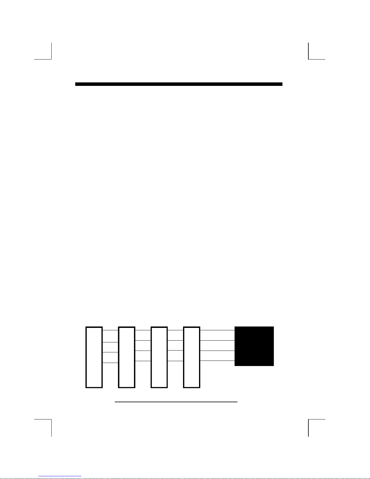
proper setting is extremely important or it may cause the system hang up. The diagram
shown below tells you how the Rotating Priority Mechanism is designed.
PCI#4
INTB
INTC
INTD
INTA
INTC
INTB
INTD
INTC
PCI#1PCI#2PCI#3
INTA
INTBINTAINTD
INTCINTBINTA
INTD
INTA
INTB
INTC
INTD
PCI
Chipset
Figure 3-7 The Combination of PCI INT# lines
Page 25
AWARD BIOS 3-13
3-6 LOAD SETUP DEFAULTS
The "LOAD SETUP DEFAULTS" function loads the system default data directly
from ROM and initialize associated hardware properly. This function will be necessary
only when the system CMOS data is corrupted.
ROM PCI/ISA BIOS (2A59CPA9)
CMOS SETUP UTILITY
AWARD SOFTWARE, INC.
STANDARD CMOS SETUP PASSWORD SETTING
BIOS FEATURES SETUP IDE HDD AUTO DETECTION
CHIPSET FEATURES SETUP SAVE & EXIT SETUP
POWER MANAGEMENT SAVING
LOAD SETUP DEFAULT
ESC: QUIT :SELECT ITEM
F10:Save & Exit Setup (Shift)F2:Change Color
Figure 3-8 LOAD SETUP DEFAULT
Load SETUP Default (Y/N)? Y
Time, Date, Hard Disk Type....
3-7 CHANGE PASSWORD
To change the password, choose the "PASSWORD SETTING" option from the
CMOS SETUP UTILITY menu and press [Enter].
NOTE : Either "Setup" or "System" must be selected in the "Security Option" of the
FEATURES SETUP menu (Refer to Figure 3-3 for the details).
1. If CMOS is corrupted or the option was not used, a default password stored in the
ROM will be used. The screen will display the following message:
Enter Password:
Press the [Enter] key to continue after proper password is given.
2. If CMOS is corrupted or the option was used earlier and the user wish to change
default password, the SETUP UTILITY will display a message and ask for a
confirmation.
Confirm Password:
3. After pressing the [Enter] key (ROM password if the option was not used) or current
password (user-defined password), the user can change the password and store new
one in CMOS RAM. A maximum of 8 characters can be entered.
Page 26

3-14 CHAPTER 3
3-8 IDE HDD AUTO DETECTION
The "IDE HDD AUTO DETECTION" utility is a very useful tool especially when you
do not know which kind of hard disk type you are using. You can use this utility to detect
the correct disk type installed in the system automatically. But now you can set HARD
DISK TYPE to Auto in the STANDARD CMOS SETUP. You don't need the "IDE
HDD AUTO DETECTION" utility. The BIOS will Auto-detect the hard disk size and
model on display during POST.
ROM PCI/ISA BIOS (2A59CPA9)
CMOS SETUP UTILITY
AWARD SOFTWARE, INC.
HARD DISKS TYPE SIZE CYLS HEADS PRECOMP LANDZONE SECTORS MODE
Primary Master : 343 665 16 65535 664 63 NORMAL
Primary Slave :
Secondary Master :
Secondary Slave :
Select Secondary Slave Option (N=Skip) : N
OPTIONS SIZE CYLS HEAD PRECOMP LANDZ SECTOR MODE
1 (Y) 0 0 0 0 0 0 NORMAL
ESC : Skip
Figure 3-9 IDE HDD AUTO DETECTION
NOTE: HDD Modes
The Award BIOS supports 3 HDD modes : NORMAL, LBA & LARGE
NORMAL mode
Generic access mode in which neither the BIOS nor the IDE controller will
make any transformations during accessing.
The maximum nunber of cylinders, head & sectors for NORMAL mode are.
1024, 16 & 63.
no. Cyclinder (1024)
x no. Head ( 16)
x no. Sector ( 63)
x no. per sector ( 512)
528 Megabytes
If user set his HDD to NORMAL mode, the maximum accessible HDD size
will be 528 Megabytes even though its physical size may be greater than that!
Page 27

AWARD BIOS 3-15
LBA (Logical Block Addressing) mode
A new HDD accessing method to overcome the 528 Megabyte bottleneck. The
number of cylinders, heads & sectors shown in setup may not be the number
physically contained in the HDD.
During HDD accessing, the IDE controller will transform the logical address
described by sector, head & cylinder into its own physical address inside the HDD.
The maximum HDD size supported by LBA mode is 8.4 Gigabytes which is
obtained by the following formula:
no. Cyclinder (1024)
x no. Head ( 255)
x no. Sector ( 63)
x bytes per secttor ( 512)
8.4 Gigabytes
LARGE mode
Extended HDD access mode supported by Award Software.
Some IDE HDDs contain more than 1024 cylinder without LBA support (in some
cases, user do not want LBA). The Award BIOS provides another alternative to
support these kinds of LARGE mode:
CYLS. HEADS SECTOR MODE
1120 16 59 NORMAL
560 32 59 LARGE
BIOS tricks DOS (or other OS) that the number of cylinders is less than 1024 by
dividing it by 2. At the same time, the number of heads is nultiplied by 2. Areverse
transformation process will be made inside INT 12h in order to access the right
HDD address the right HDD address!
Maximum HDD size:
no. Cyclinder (1024)
x no. Head ( 32)
x no. Sector ( 63)
x bytes per sector ( 512)
1 Gigabytes
Page 28

3-16 CHAPTER 3
Note:
To support LBA or LARGE mode of HDDs, there must be some
softwares involved. All these softwares are located in the Award
HDD Service Routine (1NT 13h). It may be failed to access a
HDD with LBA (LARGE) mode selected if you are running under
a Operating System which replaces the whole 1NT 13h.
UNIX operating systems do not support either LBA or LARGE and must
utility the Standard mode. UNIX can support drives larger than 528MB.
3-9 SAVE & EXIT SETUP
The "SAVE & EXIT SETUP" option will bring you back to boot up procedure
with all the changes you just made which are recorded in the CMOS RAM.
3-10 EXIT WITHOUT SAVING
The "EXIT WITHOUT SAVING" option will bring you back to normal boot
up procedure without saving any data into CMOS RAM. All of the old data in
the CMOS will not be destroyed.
Page 29

TECHNICAL INFORMATION 4-1
Chapter 4
Technical Information
4-1 I/O & MEMORY MAP
MEMORY MAP
Address Range Size Description
[00000-7FFFF] 512K Conventional memory
[80000-9FBFF] 127K Extended Conventional memory
[9FC00-9FFFF] 1K Extended BIOS data area if PS/2 mouse is installed
[A0000-C7FFF] 160K Available for Hi DOS memory
[C8000-DFFFF] 96K Available for Hi DOS memory and adapter ROMs
[E0000-EEFFF] 60K Available for UMB
[EF000-EFFFF] 4K Video service routine for Monochrome & CGA adaptor
[F0000-F7FFF] 32K BIOS CMOS setup utility
[F8000-FCFFF] 20K BIOS runtime service routine (2)
[FD000-FDFFF] 4K Plug and Play ESCD data area
[FE000-FFFFF] 8K BIOS runtime service routine (1)
I/O MAP
[000-01F] DMA controller.(Master)
[020-021] INTERRUPT CONTROLLER.(Master)
[022-023] CHIPSET control registers. I/O ports.
[040-05F] TIMER control registers.
[060-06F] KEYBOARD interface controller.(8042)
[070-07F] RTC ports & CMOS I/O ports.
[080-09F] DMA register.
[0A0-0BF] INTERRUPT controller.(Slave)
[0C0-0DF] DMA controller.(Slave)
[0F0-0FF] MATH COPROCESSOR.
[1F0-1F8 ] HARD DISK controller.
[278-27F] PARALLEL port 2.
[2B0-2DF] GRAPHICS adapter controller.
[2F8-2FF] SERIAL port 2.
[360-36F] NETWORK ports.
[378-37F] PARALLEL port 1.
[3B0-3BF] MONOCHROME & PARALLEL port adapter.
[3C0-3CF] EGA adapter.
[3D0-3DF] CGA adapter.
[3F0-3F7] FLOPPY DISK controller.
[3F8-3FF] SERIAL port 1.
Page 30

4-2 CHAPTER 4
4-2 TIME & DMA CHANNELS MAP
TIME MAP: TIMER Channel 0 System timer interrupt.
TIMER Channel 1 DRAM REFRESH request.
TIMER Channel 2 SPEAKER tone generator.
DMA CHANNELS : DMA Channel 0 Available.
DMA Channel 1 Onboard ECP (Option).
DMA Channel 2 FLOPPY DISK (SMC CHIP).
DMA Channel 3 Onboard ECP (default).
DMA Channel 4 Cascade for DMA controller 1.
DMA Channel 5 Available.
DMA Channel 6 Available.
DMA Channel 7 Available.
4-3 INTERRUPT MAP
NMI: Parity check error.
IRQ (H/W): 0 System TIMER interrupt from TIMER 0.
1 KEYBOARD output buffer full.
2 Cascade for IRQ 8-15.
3 SERIAL port 2.
4 SERIAL port 1.
5 PARALLEL port 2.
6 FLOPPY DISK (SMC CHIP).
7 PARALLEL port 1.
8 RTC clock.
9 Available.
10 Available.
11 Available.
12 PS/2 Mouse.
13 MATH coprocessor.
14 Onboard HARD DISK(IDE1) channel.
15 Onboard HARD DISK(IDE2) channel.
Page 31

TECHNICAL INFORMATION 4-3
4-4 RTC & CMOS RAM MAP
RTC & CMOS : 00 Seconds.
01 Second alarm.
02 Minutes.
03 Minutes alarm.
04 Hours.
05 Hours alarm.
06 Day of week.
07 Day of month.
08 Month.
09 Year.
0A Status register A.
0B Status register B.
0C Status register C.
0D Status register D.
0E Diagnostic status byte.
0F Shutdown byte.
10 FLOPPY DISK drive type byte.
11 Reserve.
12 HARD DISK type byte.
13 Reserve.
14 Equipment type.
15 Base memory low byte.
16 Base memory high byte.
17 Extension memory low byte.
18 Extension memory high byte.
19-2d
2E-2F
30 Reserved for ectension memory low bytw.
31 Reserved for extension memory high byte.
32 DATE CENTURY byte.
33 INFORMATION FLAG.
34-3F Reserve.
40-7F Reserved for CHIPSET SETTING DATA.
Page 32

4-4 CHAPTER 4
APPENDIX A: POST CODES
ISA POST codes are typically output to port address 80h.
POST(hex) DESCRIPTION
01-02
Reserved.
C0
03
04
05
06
07
C1
C5
08
09
Turn off OEM specific cache, shadow.
1.Initialize EISA registers (EISA BIOS only).
2.Initialize all the standard devices with default values Standard devices includes.
-DMA controller (8237).
-Programmable Interrupt Controller (8259).
-Programmable Interval Timer (8254).
-RTC chip.
Reserved
1.Keyboard Controller Self-Test.
2.Enable Keyboard Interface.
Reserved.
Verifies CMOS's basic R/W functionality.
Auto-detection of onboard DRAM & Cache.
Copy the BIOS from ROM into E0000-FFFFF shadow RAM so that POST will
go faster.
Test the first 256K DRAM.
OEM specific cache initialization. (if needed)
0A
0B
1.Initialize the first 32 interrupt vectors with corresponding Interrupt handlers
Initialize INT no from 33-120 with Dummy (Suprious)
Interrupt Handler.
2.Issue CPUID instruction to identify CPU type.
3.Early Power Management initialization. (OEM specific)
1.Verify the RTC time is valid or not.
2.Detect bad battery.
3.Read CMOS data into BIOS stack area.
4.PnP initializations including. (PnP BIOS only)
-Assign CSN to PnP ISA card.
-Create resource map from ESCD.
5.Assign IO & Memory for PCI devices. (PCI BIOS only)
Page 33

POST(hex) DESCRIPTION
TECHNICAL INFORMATION 4-5
0C
0D
0E
0F
10
11
12-13
14
15
Initialization of the BIOS Data Area. (40:ON - 40:FF)
1.Program some of the Chipset's value according to Setup. (Early Setup Value
Program)
2.Measure CPU speed for display & decide the system clock speed.
3.Video initialization including Monochromc, CGA, EGA/VGA. If no display
device found, the speaker will beep.
1.Test video RAM. (If Monochromc display device found)
2.Show messages including.
-Award Logo, Copyright string, BIOS Data code & Part No.
-OEM specific sign on messages.
-Energy Star Logo. (Green BIOS ONLY)
-CPU brand, type & speed.
-Test system BIOS checksum. (Non-Compress Version only)
DMA channel 0 test.
DMA channel 1 test.
DMA page registers test.
Reserved.
Test 8254 Timer 0 Counter 2.
Test 8259 interrupt mask bits for channel 1.
16
17
19
1A-1D
1E
1F-29
30
31
Test 8259 interrupt mask bits for channel 2.
Reserved.
Test 8259 functionality.
Reserved.
If EISA NVM checksum is good, exccute EISA initialization. (EISA BIOS only)
Reserved.
Detect Base Memory & Extended Memory Size.
1.Test Base Memory from 256K to 640K.
2.Test Extended Memory from 1M to the top of memory.
Page 34

4-6 CHAPTER 4
POST(hex) DESCRIPTION
32
33-3B
3C
3D
3E
3F-40
BF
41
42
43
1.Display the Award Plug & Play BIOS Extension message. (PnP BIOS only)
2.Program all onboard super I/O chips (if any) including COM ports, LPT
ports, FDD port ... according to setup value.
Reserved.
Set flag to allow users to enter CMOS Setup Utility.
1.Initialize Keyboard.
2.Install PS2 mouse.
Try to turn on Level 2 cache.
Note : Some chipset may need to turn on the L2 cache in this stage. But
usually, the cache is turn on later in POST 61h.
Reserved.
1.Program the rest of the Chipset's value according to Setup. (Later Setup Value
Program)
2.If auto-configuration is enabled, programmed the chipset with pre-defined
Values.
Initialize floppy disk drive controller.
Initialize Hard drive controller.
If it is a PnP BIOS, initialize serial & parallel ports.
44
45
46-4D
4E
4F
50
51
Reserved.
Initialize math coprocessor.
Reserved.
If there is any error detected (such as video, kb...), show all the error messages
on the screen & wait for user to press <F1> key.
1.If password is needed, ask for password.
2.Clear the Energy Star Logo. (Green BIOS only)
Write all CMOS values currently in the BIOS stack area back into the CMOS.
Reserved.
Page 35

POST(hex) DESCRIPTION
TECHNICAL INFORMATION 4-7
52
53
60
61
1.Initialize all ISA ROMs.
2.Later PCI initializations. (PCI BIOS only)
-assign IRQ to PCI devices.
-initialize all PCI ROMs.
3.PnP Initialzations. (PnP BIOS only)
-assign IO, Memory, IRQ & DMA to PnP ISA devices.
-initialize all PnP ISA ROMs.
4.Program shadows RAM according to Setup settings.
5.Program parity according to Setup setting.
6.Power Management Initialization.
-Enable/Disable global PM.
-APM interface initialization.
1.If it is NOT a PnP BIOS, initialize serial & paralled ports.
2.Initialize time value in BIOS data area by translate the RTC time value into
a timer tick value.
Setup Virus Protection. (Boot Sector Protection) functionality according to Setup
setting.
1.Try to turn on Level 2 cache.
Note : if L2 cache is already turned on in POST 3D, this part will be skipped.
2.Set the boot up speed according to Setup setting.
3.Last chance for Chipset initialization.
4.Last chance for Power Management initialization. (Green BIOS only)
5.Show the system configuration table.
62
1.Setup daylight saving according to Setup value.
2.Program the NUM Lock, typematic rate & typematic speed according to Setup
setting.
63
1.If there is any changes in the hardware configuration, update the ESCD
information. (PnP BIOS only)
2.Clear memory that have been used.
3.Boot system via INT 19H.
FF
System Booting. This means that the BIOS already pass the control right to the
operating system.
Unexpected Errors:
POST(hex) DESCRIPTION
B0
B1
If interrupt occurs in protected mode.
Unclaimed NMI occurs.
Page 36
4-8 CHAPTER 4
APPENDIX B: I/O CONNECTORS
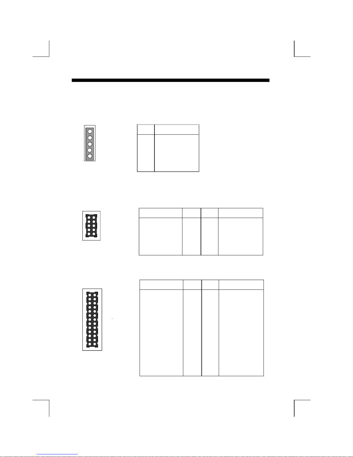
J10: PS/2 MOUSE CONNECTOR:
1
5
Pin Signal Name
1 Data (Red Wire)
2 Clock(Blue Wire)
3 GND(Green Wire)
4 NC
5 VCC(Yellow Wire)
J13,J14: Serial Ports Connector
1 6
Signal Name Pin Pin Signal Name
DCD
5 10
SIN
SOUT
DTR
GND
J15: Parallel Port Connector
Signal Name Pin Pin Signal Name
1 14
13 26
STROBEData Bit 0
Data Bit 1
Data Bit 2
Data Bit 3
Data Bit 4
Data Bit 5
Data Bit 6
Data Bit 7
ACJBUSY
PE
SLCT
1 6 DSR
2 7 RTS
3 8 CTS
4 9 RI
5 10 N.C.
1 14 AUTO FEED 2 15 ERROR 3 16 INIT 4 17 SLCT IN 5 18 Ground
6 19 Ground
7 20 Ground
8 21 Ground
9 22 Ground
10 23 Ground
11 24 Ground
12 25 Ground
13 26 N.C.
Page 37
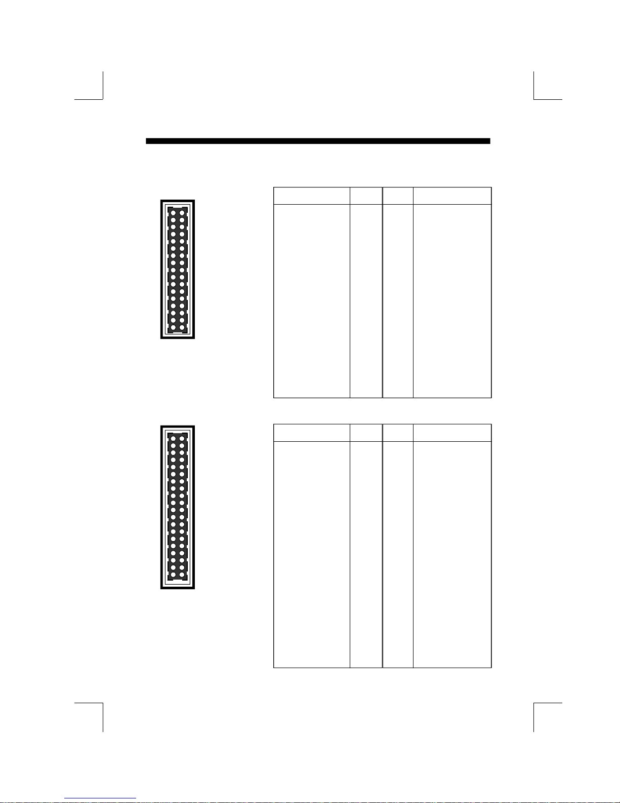
J11: Floppy Disk Connector
Signal Name Pin Pin Signal Name
TECHNICAL INFORMATION 4-9
1 2
33 34
Ground
Ground
Ground
Ground
Ground
Ground
Ground
Ground
Ground
Ground
Ground
Ground
Ground
Ground
Ground
Ground
Ground
IDE1,IDE2: Primary, Secondray Connector
1 2
39 40
Signal Name Pin Pin Signal Name
Reset IDE
Host Data 7
Host Data 6
Host Data 5
Host Data 4
Host Data 3
Host Data 2
Host Data 1
Host Data 0
Ground
DRQ3
I/O WriteI/O ReadIOCHRDY
DACK3IRQ14
Addr 1
Addr 0
Chip Select 0Activity
1 2 Ground
3 4 Host Data 8
5 6 Host Data 9
7 8 Host Data 10
9 10 Host Data 11
11 12 Host Data 12
13 14 Host Data 13
15 16 Host Data 14
17 18 Host Data 15
19 20 Key
21 22 Ground
23 24 Ground
25 26 Ground
27 28 BALE
29 30 Ground
31 32 IOCS1633 34 Ground
35 32 Addr 2
37 38 Chip Select 139 40 Ground
1 2 FDHDIN
3 4 Reserved
5 6 FDEDIN
7 8 Index 9 10 Motor Enable
11 12 Drive Select B13 14 Drive Select A15 16 Motor Enable
17 18 DIR19 20 STEP21 22 Write Data
23 24 Write Gate
25 26 Track 0027 28 Write Protect29 30 Read Data31 32 SIDE 1 SELECT33 34 Diskette
 Loading...