

Page 1
ZxA5 Series
Owner’s Manual
ZxA5-60
ZxA5-90
Page 2
s
s
t
(
y
o
r
A
R
r
’
Important Safety Instructions
The lightning flash with arrowhead symbol, within an equilateral triangle i
intended to alert the use r to the presence of uninsulated “dange rou
voltage” within the product’s enclosure that may be of sufficien
magnitude to constitut e a risk of e lectric shock to pe rsons.
The exclamation point within an equilateral triangle is intended to alert
the user to the presence of important operating and maintenance
servicing)instructions intheliterature accompanyingthe appliance.
1. Read these instructions.
2. Keep these instructions.
3. Heed all warnings.
4. Follow all instructions.
5. Do not use this apparatus near water.
6. Clean onl
7. Do not block any ventilation openings. Install in accordance with the manufacturers instructions.
8. Do not install near any heat sources such as radiators, heat registers, stoves, or other apparatus (including amplifiers) that produce heat.
9. Do not defeat the safety purpose of the polarized or grounding-type plug. A polarized plug has two blades with one wider than the other.
A grounding ty pe plug has two blades and a thir d groundin g prong. The wide blade or the third prong ar e provided for y our safety. If t he
provided plug does not fit into your outlet, consult an electrician for replacement of the obsolete outlet.
10. Protect the power cord from being walked on or pinched particularly at plugs, convenience r eceptacles, and the point where they exit from
the apparatus.
11. Only use attachments/accessories specified by the manufacturer.
12. Unplug this apparatus during lightning storms or when unused for long periods of time.
13. Refer all servicing to qualified service personnel. Servicing is required when the apparat us has been damag ed in any way, such as power supply cord or plug is damaged, liquid has been spilled or objects have fallen into the apparatus, the apparatus has been ex p os ed to r ai n or
moisture, does not operate normally , or has been dropped
14. To completely disconnect AC power from this apparatus, the power supply cord must be unplugged.
15. Do not expose this apparatus to dripping or splashing and ensu re that no object s filled w ith liquids, such as vases, ar e placed on this
apparatus.
16. The AC plug of the power supply cord shall remain readily ope rable.
with a dry cloth.
Caution: Do not exceed the marked rating of the AC Output.
Example: If each ad dit ional unit is rated 3A, a maximum of 3 units can be connected for a total of 9A.
Management of WEEE (waste electrical and electronic equipment) (applicable in Member States of the European Union and other
European countries with individual national policies on the management of WEEE) The symbol on the product or on its packaging
indicates that this product may not be treated as regular household waste, but has to be disposed through returning it at a Telex
dealer.
The asterisk within an equilateral triangle is intended to inform the user t
necessary installation or removal instructions regarding equipment o
hardware use relatingto the system.
Important Service Instructions
CAUTION: These servicing instructions are for use by qualified personnel only.Toreducetherisk of electric shock, do not
perform any servicing other than that contained in the Operating Instructions unless you are qualified to do so. Refer all
servicing to qualified service perso nnel.
1. Security regulations as stated in the EN 60065 (VDE 0860 / IEC 65) and the CSA E65 - 94 have to be obeyed when servicing the appliance.
2. Use of a AC separator transformer is manda tory during maint enance w hile the applianc e is opened, n eeds to be operated and is
connected to the AC.
3. Switch off the power before retrofitting any extensions, changing the AC voltage or the output voltage.
4. The minimum distance between part s car rying AC voltage and any accessible metal piece (metal enclosure), respectively between
the AC poles has to be 3 mm
The minimum distance between parts carrying AC voltage and any switches or breakers that are not connected to the AC (secondary
parts) has to be 6 mm
5. Replacing special components that are marked in the circuit diagram using the security symbol (Note) is only permissible when using original
parts.
6. Altering the circuitry without prior consent or advic e is not leg itimate.
7. Any work security regulations that are applica ble at the location wher e the appliance is bei ng serviced have to be strictly obeyed. This applie s
also to any regulations about the work place itself.
8. All instructions concerning the handling of MOS
Note: SAFETYCOMPONENT (HAS TOBEREPLACED WITHORIGINAL P
1 ELECTRO-VOICE
and needs to be minded at all times.
and needs to be minded at all times.
- circ uits have to be observed.
T ONLY)
®
ZxA5 Owne
s Manual
Page 3

T
r
y
p
y
y
y
p
p
g
p
k
q
gg
g
y
y
p
r
’
able of Contents
Important Safety Instructions .. ..................................................................................................... 1
ZxA5 Series Owne
Safet
Descri
S
S
S
ZxA5 Am
Sus
ZxA5 Sta
S
First ................................. ........................................................................ .......................... 3
tion ................................................................................................................................... 4
stem Features - ZxA5............................................................................................................... 4
stem Coverage - ZxA5 ............................................................................................................. 4
stem Setup - ZxA5 ................................................................................................................... 5
lifier .............................................................................................................................. 5
ending ZxA5 Speaker Systems ............................................................................................ 7
e Monitor Positions .................................................................................................... 13
ecifications ............................................................................................................................. 14
’s Manual ....................................................................................................... 2
Dimensions ................................................................................................................................ 15
Bloc
Diagram ............................................................................................................................15
Fre
uency Response, Beamwidth, and Directivity..................................................................... 16
ZxA5 Ri
Paintin
ing AccessoryReference Table ................................................................................. 17
ZxA5 Speaker Systems ............................................................................................... 18
ZxA5 Series Owner’s Manual
Thank you for choosing the Electro-Voice®ZxA5 series loudspeakersystem. This system is the
culmination of EV’s 75
manual so that
ou can understand all the features built intoyourEV system and fully utilize all its
ears of experience in transducerdesign. Please take time to consult this
erformance capabilities.
®
ELECTRO-VOICE
ZxA5 Owne
s Manual
2
Page 4
r
’
Safety First
When setting up, installing and using the Electr o-Voice® ZxA5 speaker system, there are a
number of precautions that you should follo w:
®
· When Electro-Voice
ZxA5 speakers are used for portable applicat io ns in whic h they will be
positioned directly on the floor, make sure that the floor or stage is solid and secure.
®
· Electro-Voice
ZxA5 speakers include 1-3/8 inch stand mounts to allow mounting on trip od
stands.
Make sure to:
· Check the specifications of the speak er stand t o be certain it is capable of support ing the weight
of the speaker.
· Check that the speaker stand is placed on a f lat, st able surf ace an d be s ure t o f ully e xte nd t h e
legs of the stand. Do not try to make the stand “taller” and compromise its structural integrity.
· Route cables and position the stand so that per form ers, produc tion crew and audience m embers
will not trip over the stand or cables and pull t he speaker system over. Secure cables with wire
ties or tape whenever possible.
· Do not attempt to suspend more than one speaker on a stand designed for a single speaker
· Unless you are confident that you can safely handle liftin g the weight of the spe aker ont o the
stand, ask another person to help you place it.
· If you intend to hang or fly the ZxA 5 system , only do so s afely with the correct hardware and
accessories.
WARNING:
Suspending any object is potentially dangerous and should only be
attempted by individuals who have a thorough knowledge of the techniq ues and
regulations of rigging obje cts overhead. Electro-Voice
®
strongly recommends that ZxA5
speakers be suspended taking into account all current national, federal, state and local
regulations. It is the responsibility of the installer t o ensure that ZxA5 speakers are safely
installed in accordance with all such regulati ons. If ZxA5 speakers are suspended,
®
Electro-Voice
strongly recommends that the system be inspected at least once a year.
If any sign of weakness or damage is detected, remedia l action should be taken
immediately.
There are data sheets for each EV Suspension and Array Kit that should
also be consulted prior to suspending speakers .
· Electro-Voice
®
does not recommend use of ZxA5 speakers outdoors without
protection from rain or in high moistur e environm ents .
· Electro-Voice
®
ZxA5 loudspeakers are easily capable of gener atin g s ound pr essure
levels sufficient to cause permanent hearing dam age to an yone within nor mal
coverage distance. Caution should be taken to avo id prolon ged expos ure to sound
pressure levels exceeding 90 dB.
This is a Class A product. In a domestic environment this product my cause radio interferences in which case
the user may be required to take adequate measures.
®
3 ELECTRO-VOICE
ZxA5 Owne
s Manual
Page 5
x
r
’
Description
The Electro-Voice® ZxA5 high powered loudspeakers are fully integr ated aud io systems with
carefully matched electronics and transducer s. These products make it easy to setup a high
quality sound system quickly with a minim um amou nt of cab les and external electronics. You won’t
find a speaker system available on the market that off ers the unb elievab le sou nd, incredib le
flexibility and tremendous output capa bil it y of the ZxA5 anywhere near it’s size and weight.
System Features - ZxA5
· Integrated Amplifier with 1000W LF, 250W HF
· Selectable 100 Hz High Pass
· XLR and 1/4” TRS Input Connector
· XLR Output Connector
· PowerCon Connector with Slave Through
· DVX3150 15” LF Transducer with Forced Air Cooling
· ND2 2” Voice Coil, 1” Exit Neodymium Compression Driver
· Two Models: 60° x 60° or 90° x 50° Coverage Patterns
· High Sensitivity, 133 dB Maximum SP L
· Adjustable Monitor Angle (45° or 55°)
· 3 Anchor Plates for Single Stud Fit ings and 10 I ntegra l Suspensio n Points
· Full Line of Accessories
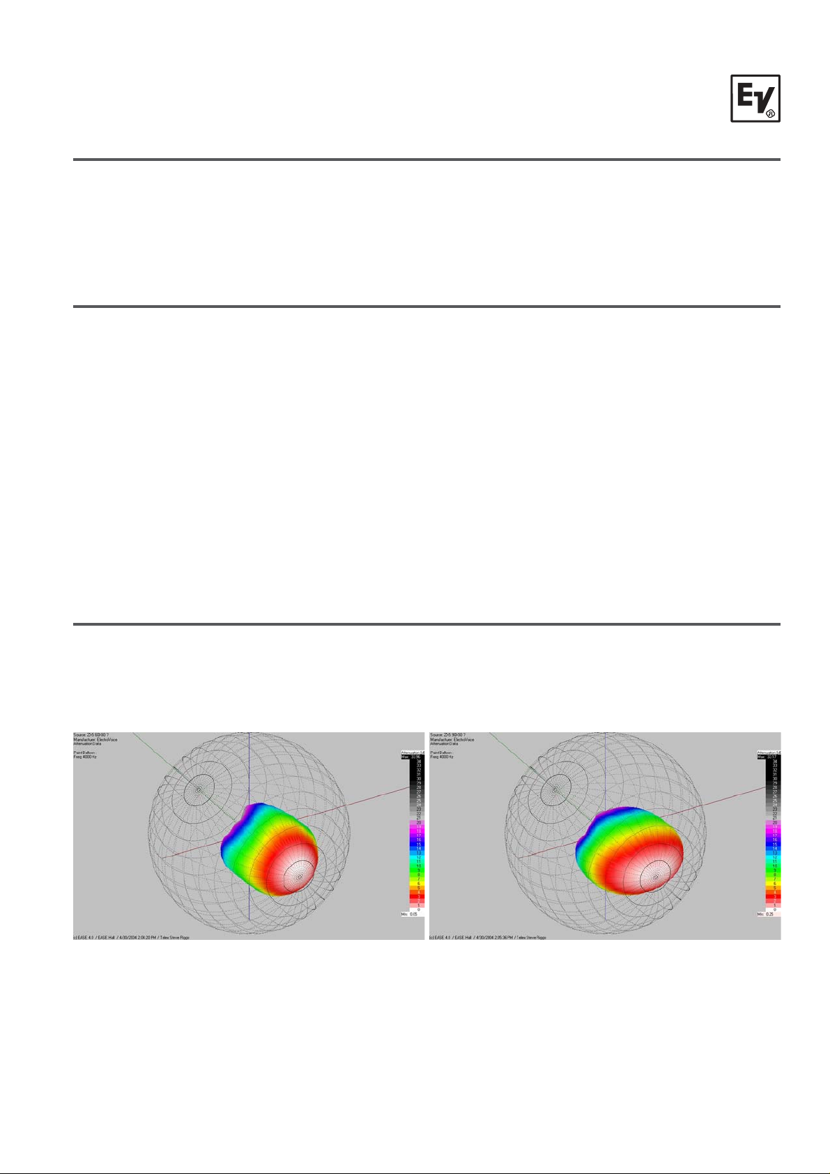
System Coverage - ZxA5
Coverage Patterns andApplications
ZxA5-60 60° x 60° coverage for long-throw and cluster applications
ZxA5-90 90°
50° for wider coverageorshorterdistances
Figure 1a:
3D EASE Directivity Balloon,
ZxA5-60, 60° x 60° Coverage
®
ELECTRO-VOICE
ZxA5 Owne
s Manual
4
3D EASE Directivity Balloon,
ZxA5-90, 90° x 50° Coverage
Figure 1b:
Page 6
r
Amp
r
’
System Setup - ZxA5
To get the ZxA5 into operation as quickly as possible, please observe the follo win g steps and
precautions:
· Plug the 3-terminal PowerCon AC cable into a grounded line receptacle. Extension cords can be
used to lengthen the AC cable as necessary but make sure that they are 3- con duct or 14 g au ge or
greater, and that they are properly grounded to avoid electrical hazards and extraneous noise.
· Be sure that the ZxA5 is plugged into an AC power source that is capable of supplying the correct
voltage. If the line voltage drops too much, the b uilt -in amplifiers won’t be able to develop their
rated power and sound quality will suffer. Under high signal conditions, the 120V ZxA5 amplifier
can draw 3 - 4 amps of current (2 amps at 240V). That means that no more than
(3) ZxA5 systems should be plugged into a single 15 amp electrical service. Be cautious of what
else is plugged into the same ele ctrical service line to avoid electrical problems and poor
performance.
CAUTION: Before turning the power on, make sure that the level controls are dow n to
avoid t
ansients orunexpected loud sound.
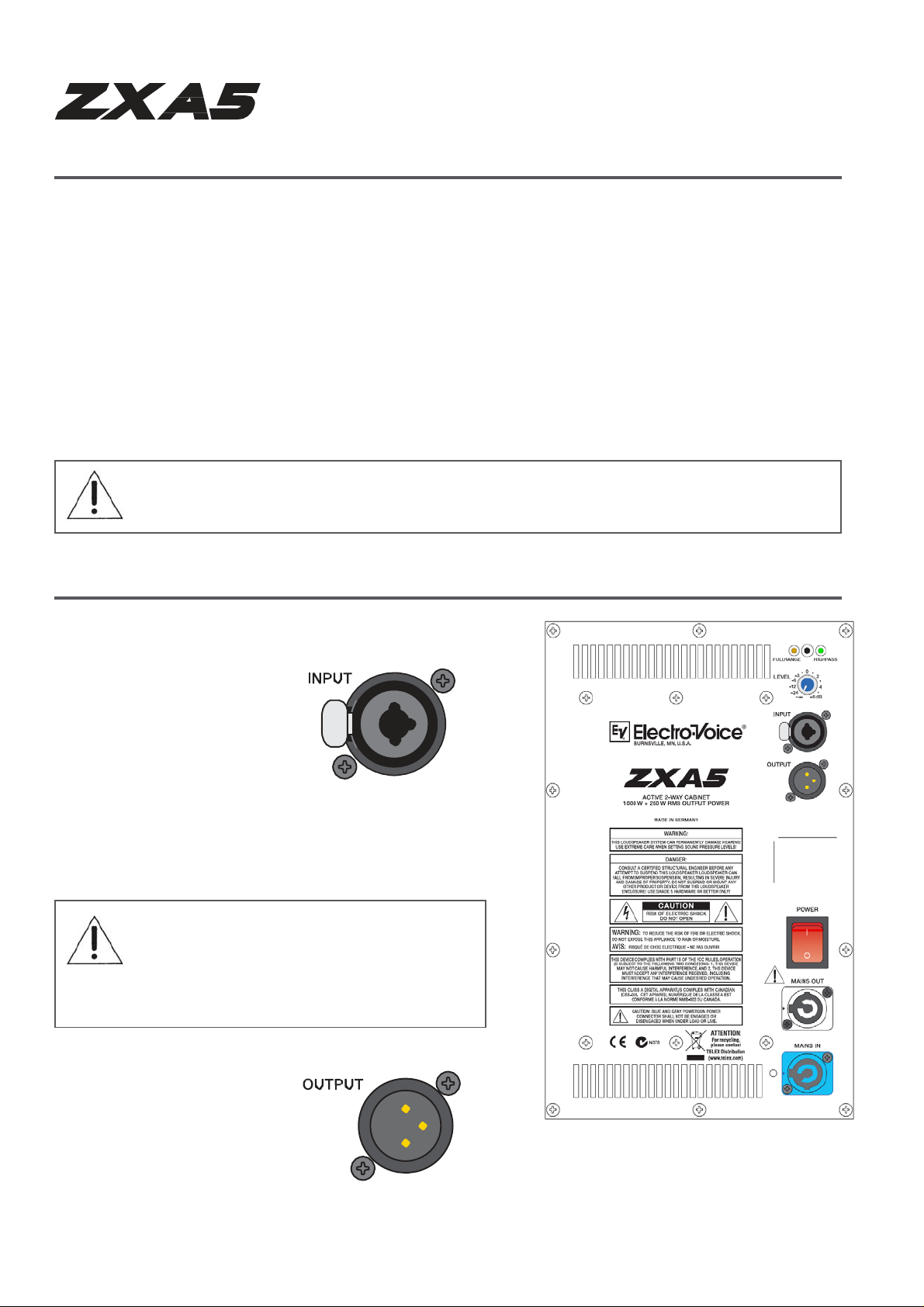
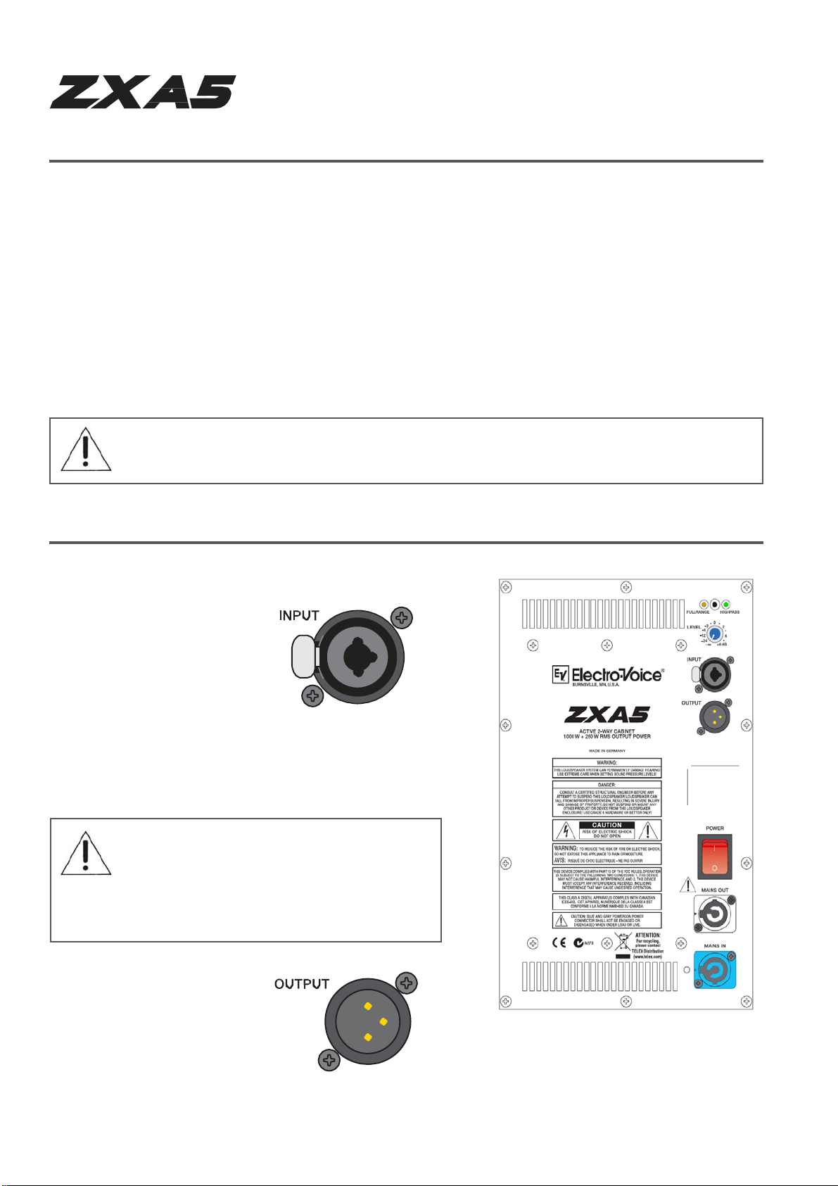
ZxA5 Amplifier
Input Signal Connector
Electronically balanced inputs
for the connection of highlevel signal sources such as
mixers, signal
processors, etc. Establishing
the connection is possible via
a combinaton 1/4” TRS and
XLR jack. Balanced
connection is recommended
to prevent noise or HFinterference.
CAUTION: Before connecting or
disconnecting any plugs, make sure to set
the level control to its counterclockwise
stop, which prevents the system and
audience from contact pops and noise.
Output Signal Connector
Output is full bandwidth pass
through.
Figure 2:
lifier Panel, ZxA5
5 ELECTRO-VOICE
®
ZxA5 Owne
s Manual
Page 7
)
A
A
)
q
r
’
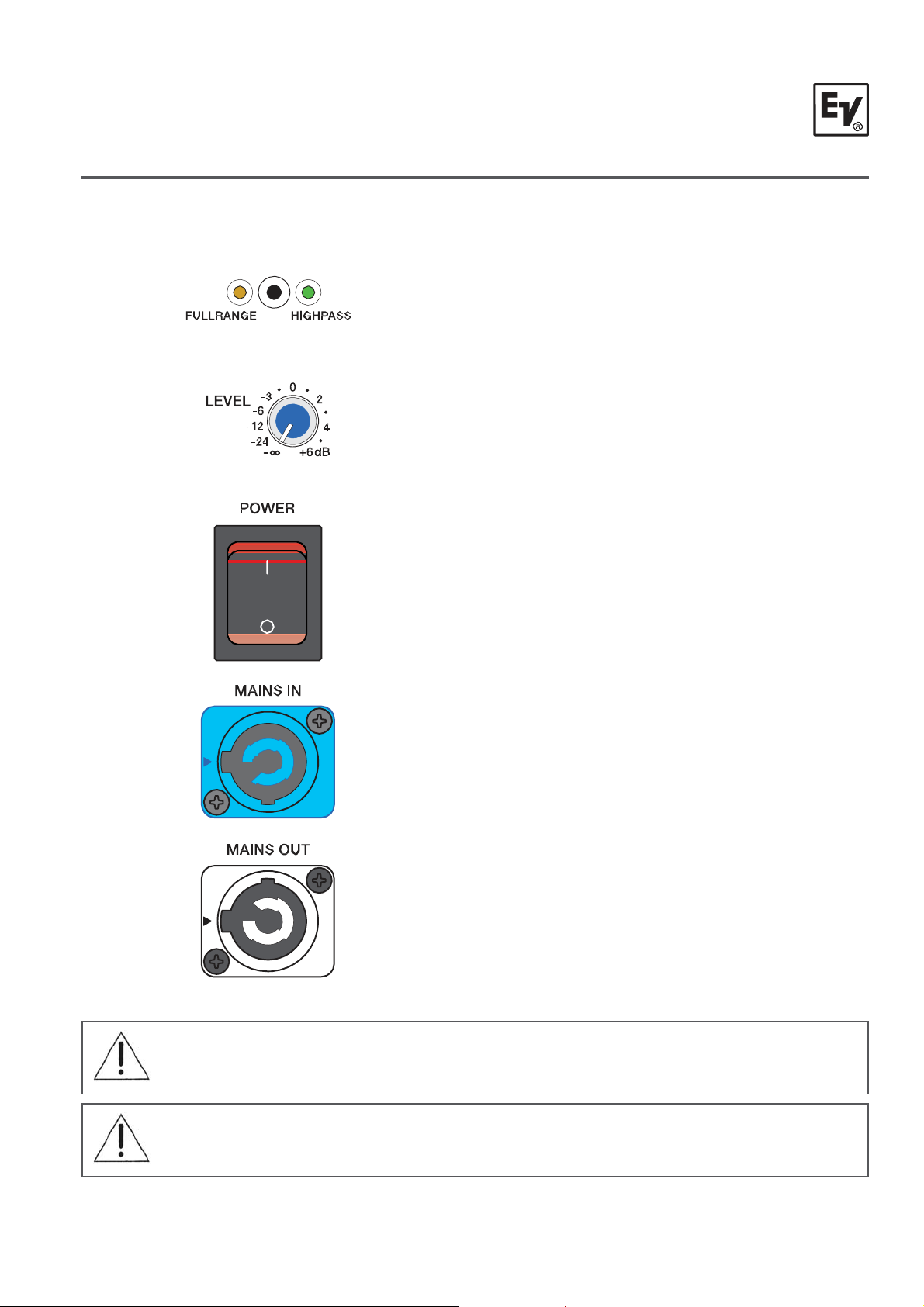
ZxA5 Amplifier (cont’
CrossoverMode Switch
Selects between 40 Hz highpass filter for Fu llra ng e
use, and 100 Hz highpass filter for use with a
subwoofer. It is not recommended that you use a
ZxA5 in Fullrange mode with subwoofers.
Level
This control sets the output level of the Z xA5 in a
∞
range between -
dB and +6dB. The internal power
amplifier provides a nominal input sensitivit y of
+6dBu.
Power Switch
C switch for switching the ZxA5’s power ON or
OFF. The switch lights after turning the power ON.
If the switch is not lit upon turning the power on,
make sure that the AC cord is correctly connected.
If the AC cord is correctly connected and the AC
switch does not light upon power-on, p le ase
contact your local dealer.
Mains In
C connection is established via a PowerCon
connector. A 15’ (5m) long AC cord wit h Pow erCon
plug is supplied.
Mains Out
The PowerCon AC out socket allows the
connection of additional ZxA 5 Systems .
To prevent AC network overload, connecting more
than (3) ZxA5 Systems to a single AC outlet (10A -
is not recommended.
16A
CAUTI ON:
Blue and grey PowerCon power connector shall not be engaged or
disengaged when under load or live.
CAUTI ON: This appliance has no user-serviceable parts inside. Leave any servicing
and maintenance to
ualified service technicians only.
®
ELECTRO-VOICE
ZxA5 Owne
s Manual
6
Page 8

r
’
Suspending ZxA5 SpeakerSystems
ZxA5 enclosures have 5 steel anchor points internally mounted on the top, bottom, and rear.
Single stud fittings can be attached to these anchor plates and us ed as suspension points. Each
of these anchor plates also has a M8 thread to accept rated forged M8 shoulder eyebolts. In
addition to these points there are five ad ditional M 8 thre ade d point s; two on t he handle s ide, and
three on the rear. These points can be used for suspending ZxA5s vertically, horizo ntally,
individually, in clusters, or to attach to EV mounting brackets. Working load limits for the ZxA5 and
fittings are shown in Figure 3.
Figure 3:
Working Load-Limit Ratingof ZxA5 Speaker System
Prior to each use, inspect the grid assembly or suspension point(s) and associated hardw are for
any cracks, deformations, broken welds, corrosion, missin g or dam aged compon ents w hic h could
reduce the grid assembly or suspension point(s) strength. Replace any d amag ed hardwar e. Never
exceed the limitations or maximum recommended load inte nded for grid assemb ly des ign or
suspension point(s). As an added safety measure, it is suggested that the user install a second
suspension point back to the grid (or building structural supports). This redundant safety point
should have as little slack as possible (less than one inc h is pr efera ble).
Prior to each use, inspect the loudspeaker enclosures for any cracks, deformations, missing or
damaged components, which could reduce enclosure strength. Inspect the brack et assembly on
the enclosures for any cracks, deformat ions, missing or loose screws which could reduce the
flying hardware strength. Replace any lou dspeaker systems t hat are damaged or missing
hardware. Never exceed the limitations or maximum recommended load for the ZxA5 systems.
®
7 ELECTRO-VOICE
ZxA5 Owne
s Manual
Page 9
v
(
(
)
)
)
s
(
)
r
’
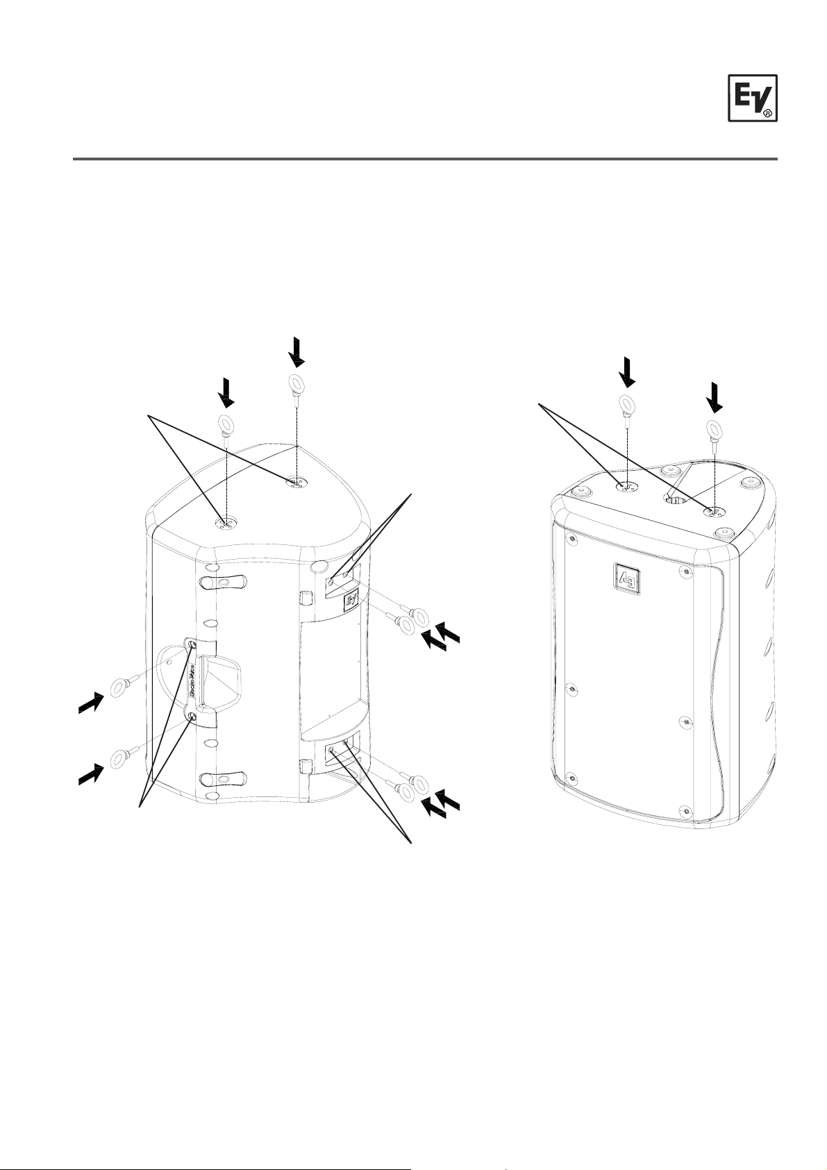
Suspending ZxA5 SpeakerSystems(cont’)
ZxA5 M8 Suspension Points
Metric (M8) inserts are equipped on the top and bot tom of t he enclos ure, aro und t he handle, and
on the back of the enclosure for a total of 10 points. The inserts can be us ed t o attach forge d
eyebolts or rigging brackets.
(2) M8 Suspension Points
(Single-Stud Anchor Plate
Remo
al Required)
(2) M8 Suspension Points
Decal Removal Required)
(2) M8 Suspension Points
Decal Removal Required
(2) M8 Suspension Points
(Removal of Handle Bolts
ELECTRO-VOICE
Required
(2) M8 Suspension Points
(Single-Stud Anchor Plate/
Decal Removal Required)
Figure 4a:
ZxA5 M8 Suspension Points (Top, Handle, Rear
®
ZxA5 Owne
s Manual
8
Figure 4b:
ZxA5 M8 Suspension Point
Bottom
Page 10
(x1)
(x2)
(
)
-
r
’
Suspending ZxA5 SpeakerSystems(cont’)
Suspending the ZxA5 using optional Electro-Voice Single-Stud Rigging Kits
The ZxA5 is shipped with three single-stud anchor plates for rigging with single-stud rigging. There
are two more locations on the bottom to mount single-st ud anc hor plates f or flying t he Zx A5
upside-down or horizontally. All of these locations
can facilitate M8 Eyebolts if desired as well.
Figure 5:
Suspending the ZxA5 Using Included Single-Stud
Anchor Plates
Kit Used (Left View) -
SSK-1 Single-Stud Rigging Kit
Kits Used (Right View) -
SSK-1 Single-Stud Rigging Kit
EBK-3 Forged M8 Eyebolt Kit (x1)*
*EBK-3 on Bottom ofTop
Enclosure
not shown, see Figure 3b
Step 1: Remove Decals
Step 2: Attach Single-Stud Anchor Plates
Removed from the Top of the Enclosure or
optional RK-Z Kit (shown) or Eyebolts (not
shown)
Figure 6:
Suspending the ZxA5 Ups ide-Down Using
Included Single-Stud Anchor Plates and Single-
Stud Rigging Ki t
Kits Used
RK-Z Single-Stud Anchor Plate Kit (x1)
SSK-1 Single-Stud Rigging Kit (x1)
9 ELECTRO-VOICE
®
ZxA5 Owne
s Manual
Page 11

-
K
-
)
A
-
K
-
)
r
’
Suspending ZxA5 SpeakerSystems(cont’)
Horizontal Suspension of the ZxA5
The ZxA5 is capable of being suspended horizontally from t he side (ha ndle) or downw ard f rom t he
rear with the use of M8 Eyebolts.
Figure 7:
Suspending the ZxA5 Downward from Rear Using
Optional Forged Eyebolt Kit*
EB
Kit Used
*Note - When suspending from the rear M8 suspension
points, it is recommended that the (2) left M8 suspension
points are used on the rear of the enclos ure for best w eig ht
distribution in relation to enclosure’s center of gravity.
3 Forged M8 Eyebolt Kit (x1
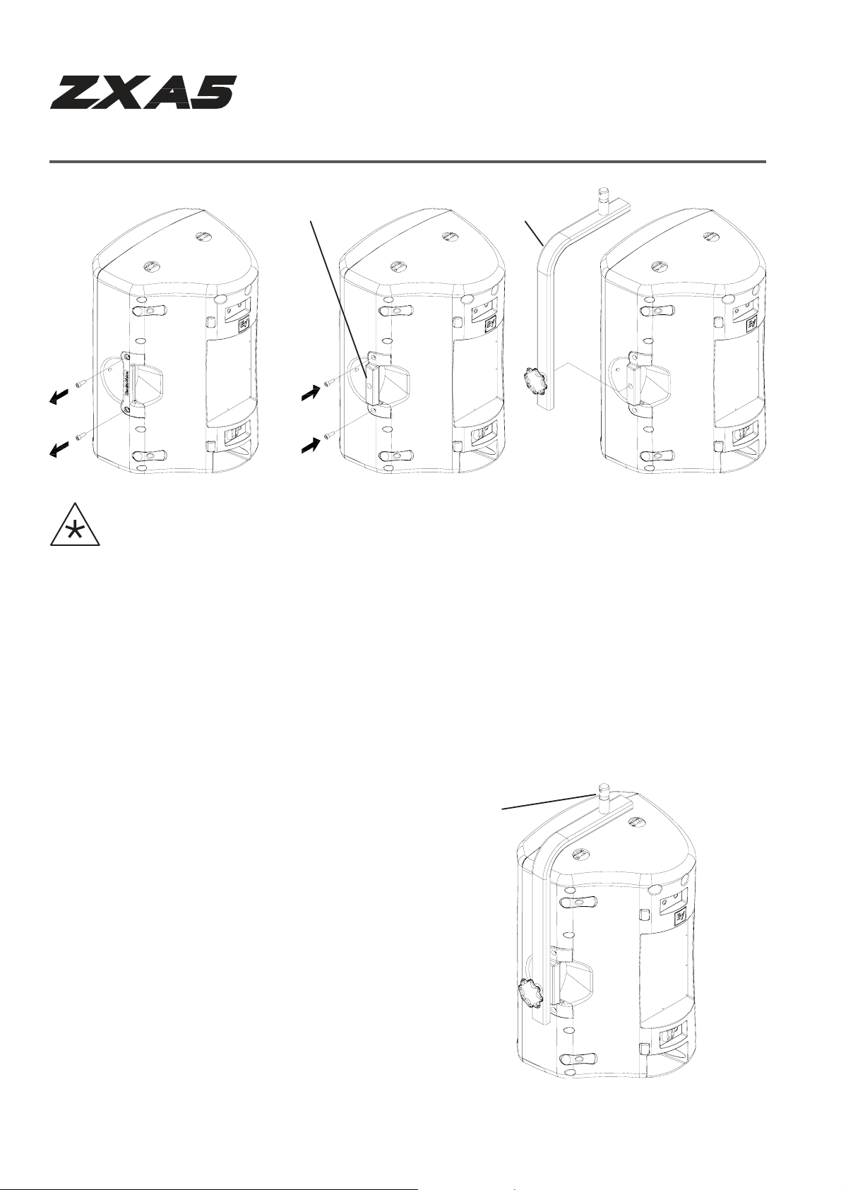
Step 1: Remove Handle Bolts Step 2:Attach Eyebolts
Figure 9:
Suspending the ZxA5 Horizontally from Handle
Using Optional Forged Eyebolt Kit
EB
Kit Used
3 Forged M8 Eyebolt Kit (x1
Figure 8:
ssembling Eyebolts to Handle
for Horizontal Suspension
®
ELECTRO-VOICE
ZxA5 Owne
s Manual
10
Page 12
VSA
p
A
T
p
r
’
Suspending ZxA5 SpeakerSystems(cont’)
Step 1: Remove Handle Bolts
and Handle
ssembling HA-5 Adapter for use with VS A-1 Strong -Arm Mount
HA-5 Handle Mount
Ste
2:Attach HA-5 and Handle Bolts Step3:Attach VSA-1 Strong-Arm Mount
HA-5 Handle Adapter Kit (x1)
VSA-1 Strong-A rm Mount (x1 )
-1 Strong-Arm
Figure 10:
Kits Used -
Arraying and Suspending the ZxA5 using optional Electro-Voice Mounting or Array
Brackets
Figures 11 and 12 show several applications using EV mounting and array brackets. Carefully
follow the instructions in this manual & the user manual packaged with EV brackets, and always
use safe rigging practices when suspending ZxA5.
Spigot toAttach to Beam or
russ Clam
Figure 11:
Suspending the ZxA5 Vertically from Handle Using Optional
Handle Adapter and St rong-Arm Mount
Kits Used -
HA-5 Handle Adapter Kit (x1)
VSA-1 Strong-A rm Mount (x1 )
*Note - Please consult VSA-1 User Manual for additional
information.
11 ELECTRO-VOICE
®
ZxA5 Owne
s Manual
Page 13

(
W
(
g
g
ging
)
r
g
)
r
g
)
y
Ang
A
r
’
Suspending ZxA5 SpeakerSystems(cont’)
Kit Used - MB5
Kits Used - CB5 Array Bracket Kit (x1)*
Wall/Ceiling MountingBracket
all Configuration)
SSK-1 Sin
le-Stud Ri
Kit Used - MB5Wall/Ceiling MountingBracket
Kit Used - CB5Array Bracket Kit(x2)*
Kit(x1
NOTE: Do not
exceed working
load limit for
individual rigging
points when
arraying the
ZxA5. (See
Figure 3,
Page 7)
CeilingConfiguration)
Kits Used - CB5 Array Bracket Kit (x2)*
SSK-1 Single-Stud Rigging Kit (x2)
EBK-3 Fo
*Note - CB5 Array Kits can be used for 60° or 90° Spla
ed M8 Eyebolt Kit(x1
Kits Used - CB5Array Bracket Kit(x4)*
EBK-3 Fo
ed M8 Eyebolt Kit(x1
les
Figure 12:
rrayingand Suspendingthe ZxA5
®
ELECTRO-VOICE
ZxA5 Owne
s Manual
12
Page 14

r
’
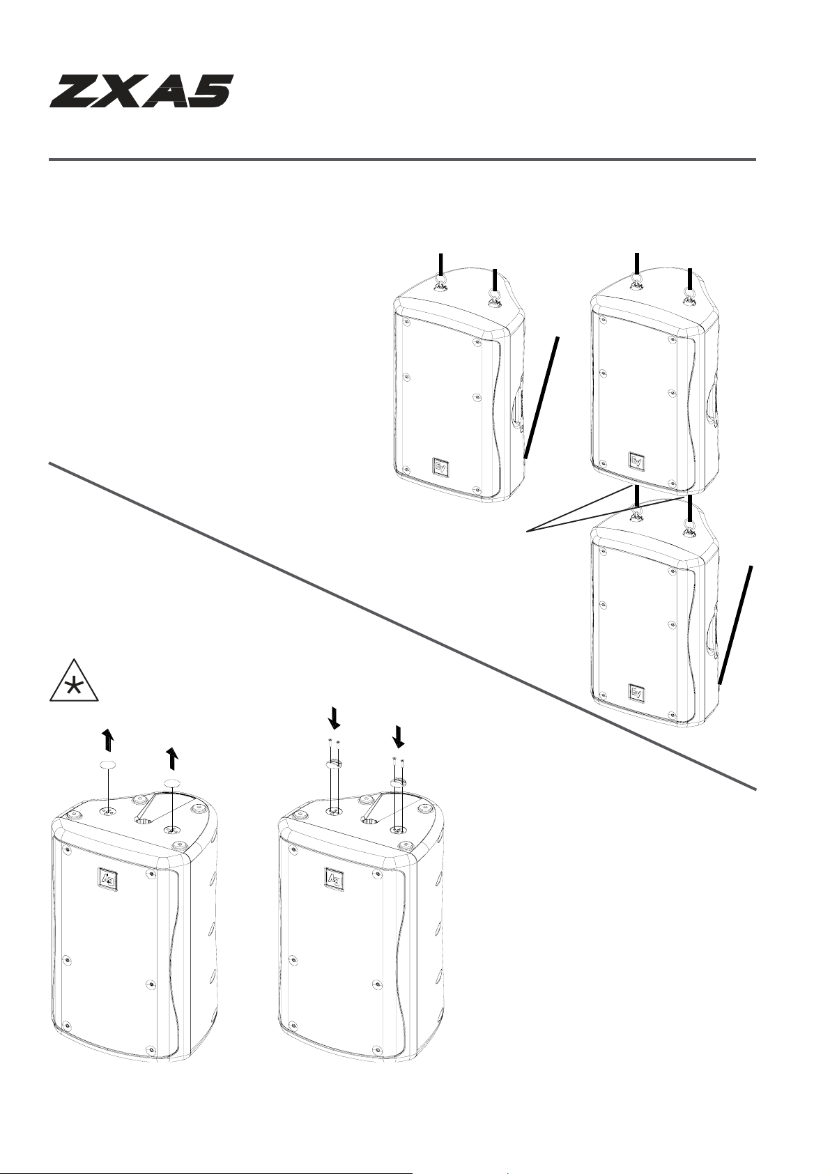
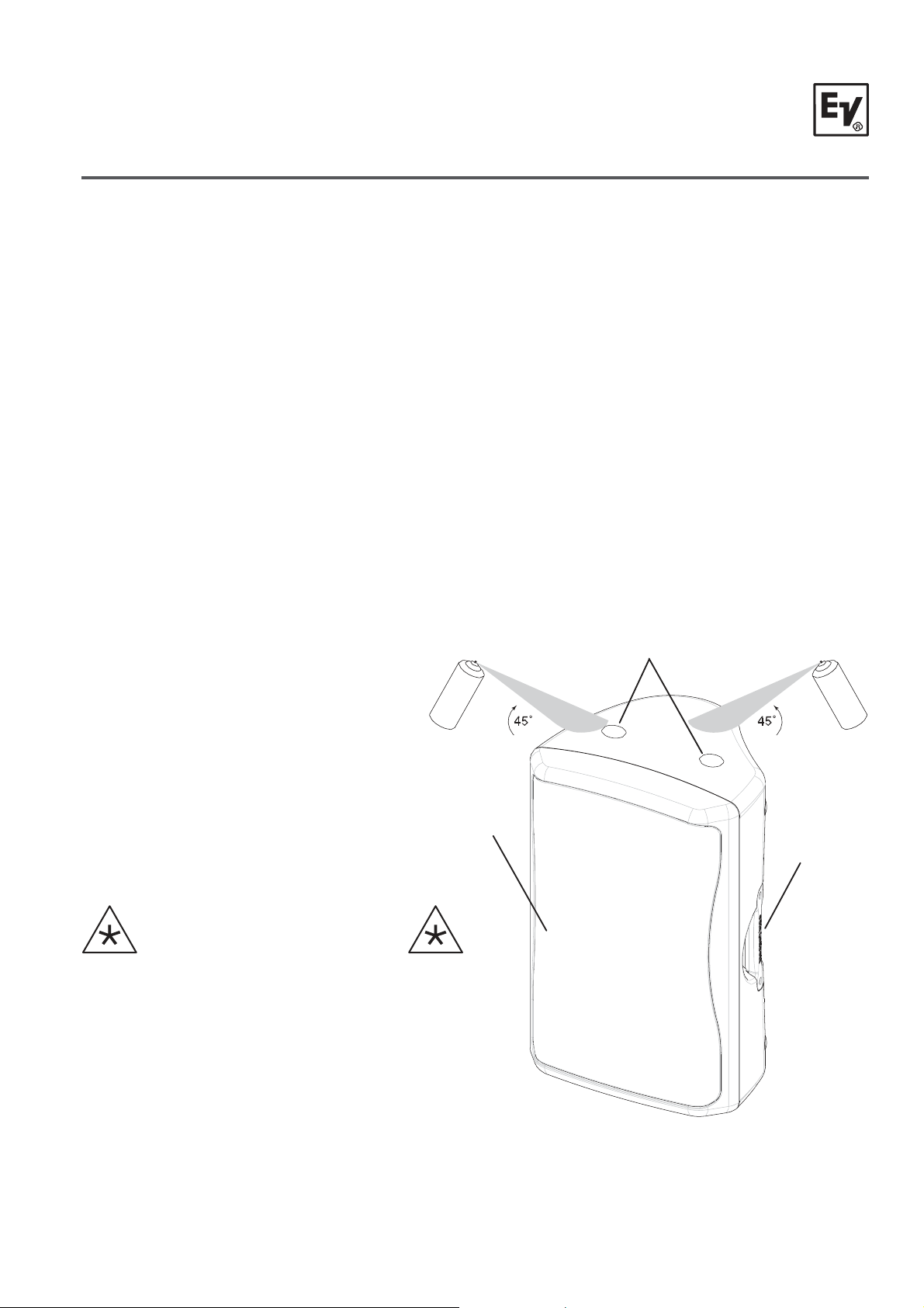
ZxA5 Stage Monitor Po sitio ns
ZxA5 as a Monitor
By design the ZxA5 is a perfect solution for stage monitors. As different stage sizes require
different monitor angles, the ZxA5 offers two angles without any additional accessories.
Step 1: Remove Monitor Foot
Screws
Switching the Monitor Feet from the 45° to 55° Positions
Step 2: Rotate Monitor Feet 180° Step 3: Re-attach Monitor Feet
and Screws
Figure 13:
Figure 14a:
ZxA5 asMonitor in 45° Position
ZxA5 as Monitor in 55° Position
Figure 14b:
CAUTIO N: When flipped to 55° the feet protrude from the enclosure. Care should be
taken when moving the enclosure, since damage to the feet or enclosure might occur if
the system is dropped or slid across a rough surface. It is recommended that the feet be
returned to the 45° position for transport.
13 ELECTRO-VOICE
®
ZxA5 Owne
s Manual
Page 15

T
r
’
echnical Specifications
Freq. Response1 (-3 dB): 58Hz – 18kHz
Freq. Range1 (-10dB): 50Hz – 20kHz
Max Calculated SPL: 133 dB
Horizontal Coverage: 90° or 60°
Vertical Coverage: 50° or 60°
LF Amplifier Power: 1000W RMS
HF Amplifier Power: 250W RMS
LF Transducer: DVX3150, 15in (300mm) Driver
HF Transducer:
Crossover Frequency: 1.5 kHz
Input Connector: XLR and 1/4” TRS Combination
ND2-16, 1in. (25.4mm) exit Neodymium
Compression Driver
Output Connector: XLR
Power Requirement:
Enclosure Material: Polypropylene Structural Foam
Suspension:
Grille:
Dim (H x W x D):
Net Weight: 50.5 Ibs (22.9 kg)
Shipping Weight: 58.9 Ibs (26.7 kg)
1
Half Space measurement
120 VAC, 50-60 Hz, or
230 VAC, 50-60 Hz
Enclosure has locations for 5 SingleStud Attatchment Plates and 10 Forged
Steel Eyebolts – 2 on Top, 2 on Bottom,
2 on Side, and 4 on Rear of Enclosure
Polyester Powder Coated, 16GA
Galvanized Steel
27.26” x 17.57” x 16.16”
(692mm x 446mm x 411mm)
®
ELECTRO-VOICE
ZxA5 Owne
s Manual
14
Page 16

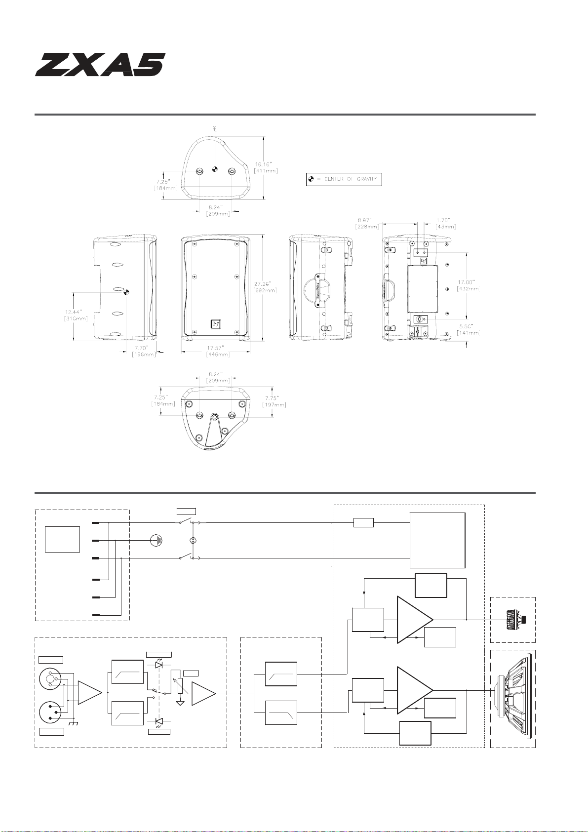
Dimensions
Top V
V
–
r
’
Left
iew Front View RightView Rear View
iew
Block Diagram
MAINS-L
MAINS
INPUT
OUTPUT
120V AC
230V AC
50 Hz
MAINS-E
60 Hz
MAINS-N
MOUT-L
MOUT-E
MOUT-N
40Hz,
100Hz, 24dB, LR
HPF
24dB, LR
HPF
FULLRANGE
MID/HIGH
POWER
Bottom View
LEVEL
HPF and PEQ
1.5kHz, 24dB, LR
LPF and PEQ
1.5kHz, 24dB, LR
T10A@120V
@ 230V
T6.3A
LIMITER HIAMP
Class DAmp
LIMITER
POWER SUPPLY
TURN ON DELAY
THERMAL
PROTECTION
LO AMP
THERMAL
PROTECTION
PROTECTION
Module
PROTECTION
HF
LF
®
15 ELECTRO-VOICE
ZxA5 Owne
s Manual
Page 17

y
q
g
g
y
r
’
Frequency Response, Beamwidth and Directivit
ZxA5-60, 60° x 60° Coverage
Frequency Response:
110
100
90
80
70
20
50 100
Beamwidth:
Fre que ncy (Hz)
1000
Full Range, Full Space
h Pass, Full Space
Hi
10000 20000
ZxA5-90, 90° x 50° Coverage
Fre
uencyResponse:
110
100
90
80
70
20 50 100 1000
Fre que ncy (Hz)
Beamwidth:
FullRange, Full Space
hPass, Full Space
Hi
10000 20000
Directivit
:
Directivity:
®
ELECTRO-VOICE
ZxA5 Owne
s Manual
16
Page 18

g
ging
r
y
r
’
ZxA5 Ri
Accesso
Model Description Part No.
CB5-B Array Bracket Kit, Black Finish 301625-001
CB5-W Array Bracket Kit, White Finish 301625-002
MB5-B Wall/Ceiling Mounting Bracket Kit, Black Finish 301626-001
MB5-W Wall/Ceiling Mounting Bracket Kit, White Finish 301626-002
SSK-1 Single-Stud Rigging Kit (Set of 3) 301633-000
EBK-3 Forged M8 Eyebolt Kit (Set of 3) 301634-000
RK-Z Single-Stud Anchor Plate Kit (Set of 3) 301812-000
ReferenceTable
TMK-ZX
HDC-5 Heavy-Duty Stackable Cover, Black 301813-001
HA-5 Handle adaptor for use with VSA-1 301811-001
VSA-1 Vertical Strong Arm ACC000007-001
TCA-1 Trussclamp adaptor for VSA-1 ACC000012-001
Truss Mount Kit, Includes VSA-1, TCA-1, and
HA-5 (Black)
FCC Information
1. IMPORTANT: Do not modify this unit! Changes or modifications not expressly approved by
the manufacturer could void the user’s authority, granted by the FCC, to operate the
equipment.
2. NOTE: This equipment has been tested and found to comply with the limits for a Class A
digital device, pursuant to Part 15 of the FCC Rules. These limits are designed to provide
reasonable protection against harmful interference in a residential installation. This
equipment generates, uses and can radiate radio frequency energy and, if not installed and
used in accordance with the instructions, may cause harmful interference to radio
communications. However, there is no guarantee that interference will not occur in a
particular installation. If this equipment does cause harmful interference to radio or
television reception, which can be determined by turning the equipment off and on, the user
is encouraged to try to correct the interference by one or more of the following measures:
• Reorient or relocate the receiving antenna.
• Increase the separation between the equipment and receiver.
• Connect the equipment into an outlet on a circuit different from that to which the receiver
is connected.
• Consult the dealer or an experienced radio/TV technician for help.
KIT000007-001
FCC INFORMATI O N (U S A)
17 ELECTRO-VOICE
®
ZxA5 Owne
s Manual
Page 19
T
g
P
r
’
Painting ZxA5 SpeakerSystems
Painting a ZxA5 Enclosure
The ZxA5 Loudspeaker Enclosures are made of a high performanc e Polyprop ylene mate rial. For
best paint adhesion, we recommend a “Plastic Adhesion Promoter” be applied before any paint.
Sherwin Williams Plastic Adhesion Promoter UP07226 is a good example (See Telex document
number LIT000066-000 for further details.) Once P lastic Adhesion Promoter is applied fo llow the
manufacturer’s painting directions as you would normally.
Painting a ZxA5 Grille
Remove grille from loudspeaker and remove the backing material & logo from grille prior to painting.
Once the paint is dry, reapply the backing material an d logo to the grille. Spray adhesive such as
3M Super 77 may help adhere the backing material to the grille.
Additional Precautions to be
aken
Prior to painting, be sure to take precautions not to get paint into the transducers. This can be
done by masking the grille, temporarily rem ovin g t he gr ille and ma sking the transducers, or by
temporarily removing the grille and tem por ar ily remo ving the transducers. Precautions must also
be taken not to get paint into any exposed electrical components by masking them off prior to
painting. It is also recommended that any exposed r iggin g po ints, war n ing lab e ls, or instruction
labels be masked off for ease of fu ture op erati on.
Riggin
Grille Masked
WARNING: It is critical to the system’s operation
that all transducers and exposed electrical
components be masked off prior to painting.
oints Masked
ZxA5 Enclosure
Painting View:
Paintingthe ZxA5 Enclosure
®
ELECTRO-VOICE
ZxA5 Owne
s Manual
18
Page 20

Page 21

s
g
ZxA5 Serie
Bedienungsanleitun
ZxA5-60
ZxA5-90
Page 22
A
R
)
g
Wichtige Sicherheitshinweise
Das Blitzsymbol innerhalb eines gleichseitigen Dreiecks soll den
Benutzer vor dem Vorhandensein von nicht isolierten "gefährlichen
Spannungen" warnen, die innerhalb des Gehäuses auftreten und
hinreichend groß sein können, um zu einer Gefahr des elektrischen
Schlages für Personen zu werden.
Das Ausrufezeichen innerhalb eines gleichseitigen Dreiecks soll
den Benutzer auf das Vorhandensein von wichtigen Bedienungsund Wartungs-Anweisungen in diesem Geräte-Handbuch
aufmerksam machen.
Das Sternchen innerhalb eines gleichseitigen Dreiecks soll den
Benutzer auf das Vorhandensein von nützlichen InstallationsHinweisen bzw. Hinweisen zur Entfernung von Geräteteilen oder
1. Lesen Sie diese Hinweise.
2. Heben Sie diese Hinweise auf.
3. Beachten Sie alle Warnungen.
4. Richten Sie sich nach den Anweisungen.
5. Betreiben Sie das Gerät nicht in unmittelbarer Nähe von Wasser.
6. Verwenden Sie zum Reinigen des Gerätes ausschließlich ein trockenes Tuch.
7. Verdecken Sie keine Lüftungsschlitze. Beachten Sie bei der Installation des Gerätes stets die entsprechenden Hinweise des Herstellers.
8. Vermeiden Sie die Installation des Gerätes in der Nähe von Heizkörpern, Wärmespeichern, Öfen oder anderer Wärmequellen.
9. Achtung: Gerät nur an Netzsteckdose mit Schutzleiteranschluss betreiben. Setzen Sie die Funktion des Schutzleiteranschlusses des
mitgelieferten Netzanschlusskabels nicht außer Kraft. Sollte der Stecker des mitgelieferten Kabels nicht in Ihre Netzsteckdose passen, setzen
Sie sich mit Ihrem Elektriker in Verbindung.
10. Sorgen Sie dafür, dass das Netzkabel nicht betreten wird. Schützen Sie das Netzkabel vor Quetschungen insbesondere am Gerätestecker
und am Netzstecker.
11. Verwenden Sie mit dem Gerät ausschließlich Zubehör/Erweiterungen, die vom Hersteller hierzu vorgesehen sind.
12. Ziehen Sie bei Blitzschlaggefahr oder bei längerem Nichtgebrauch den Netzstecker.
13. Überlassen Sie sämtliche Servicearbeiten und Reparaturen einem ausgebildeten Kundendiensttechniker. Servicearbeiten sind notwendig,
sobald das Gerät auf irgendeine Weise beschädigt wurde, wie z.B. eine Beschädigung des Netzkabels oder des Netzsteckers, wenn eine
Flüssigkeit in das Gerät geschüttet wurde oder ein Gegenstand in das Gerät gefallen ist, wenn das Gerät Regen oder Feuchtigkeit ausgesetzt
wurde, oder wenn es nicht normal arbeitet oder fallengelassen wurde.
14. Stellen Sie bitte sicher, dass kein Tropf- oder Spritzwasser ins Geräteinnere eindringen kann. Stellen Sie keine mit Flüssigkeiten gefüllten
Objekte, wie Vasen oder Trinkgefässe, auf das Gerät.
15. Um das Gerät komplett spannungsfrei zu schalten, muss der Netzstecker gezogen werden.
16. Beim Einbau des Gerätes ist zu beachten, dass der Netzstecker leicht zugänglich bleibt.
Vorsicht: Überschreiten Sie nicht die angegebenen Grenzwerte des Wechselstromanschlusses.
Beispiel: Wenn jedes zusätzliche Gerät mit 3A angegeben ist, können für einen erlaubten Gesamtstrom von 10A nur
Entsorgung von gebrauchten elektrischen und elektronischen Geräten (Anzuwenden in den Ländern der Europäischen Union und
maximal 3 Gräte (9A) angesteckt werden.
anderen europäischen Ländern mit einem separaten Sammelsystem für diese Geräte) Das Symbol auf dem Produkt oder seiner
Verpackung weist darauf hin, dass dieses Produkt nicht als normaler Haushaltsabfall zu behandeln ist, sondern bei einem Telex
Händler abgegeben werden muss.
anderer Hardware bezüglich des Systems aufmerksam machen.
Wichtige Service-Anweisungen
VORSICHT: Diese Service-Anweisungen sind nur für qualifiziertes Personal gedacht. Um die Gefahr des elektrischen Schlages zu
1. Bei Reparaturarbeiten im Gerät sind die Sicherheitsbestimmungen nach EN 60065 (VDE 0860) einzuhalten.
2. Bei allen Arbeiten, bei denen das geöffnete Gerät mit Netzspannung verbunden ist und betrieben wird, ist ein Netz trenntransformator zu verwenden.
3. Vor einem Umbau mit Nachrüstsätzen, Umschaltung der Netzspannung oder sonstigen Modifikationen ist das Gerät stromlos zu schalten.
4. Die Mindestabstände zwischen netzspannungsführenden Teilen und berührbaren Metallteilen (Metallgehäuse) bzw. zwischen den Netzpolen
betragen 3 mm und sind unbedingt einzuhalten.
Die Mindestabstände zwischen netzspannungsführenden Teilen und Schaltungsteilen, die nicht mit dem Netz verbunden sind (sekundär),
betragen 6 mm und sind unbedingt einzuhalten.
5. Spezielle Bauteile, die im Stromlaufplan mit dem Sicherheitssymbol gekennzeichnet sind (Note), dürfen nur durch Originalteile ersetzt werden.
6. Eigenmächtige Schaltungsänderungen dürfen nicht vorgenommen werden.
7. Die am Reparaturort gültigen Schutzbestimmungen der Berufsgenossenschaften sind einzuhalten. Hierzu gehört auch die Beschaffenheit des
Arbeitsplatzes.
8. Die Vorschriften im Umgang mit MOS - Bauteilen sind zu beachten.
1 ELECTRO-VOICE
vermeiden, führen Sie keine anderen Instandhaltungen durch als diejenigen, die in der Bedienungsanleitung enthalten
sind, es sei denn Sie sind dazu qualifiziert. Überlassen Sie jegliche Reparaturarbeiten qualifiziertem Service-Personal.
Note: SAFETYCOMPONENT (HAS TOBEREPLACED WITHORIGINAL P
T ONLY
®
ZxA5 Bedienungsanleitun
Page 23

y
A
r
A
k
r
g
Inhaltsverzeichnis
Wichtige Sicherheitshinweise....................................................................................................... 1
ZxA5 Serie Bedienungsanleitung ……………….......................................................................... 2
Safet
Beschreibung .............................................................................................................................. 4
Systemeigenschaften - ZxA5 ........................................................................................................ 4
System Abstrahlbereich - ZxA5 .................................................................................................... 4
Systemaufstellung - ZxA5 ............................................................................................................ 5
ZxA5 Verstärkerteil.......................................................................................................................... 5
ZxA5 Bühnen -Monito
Technische Daten ..................................................................................................................... 14
First ................................................................................................................................... 3
ufhängung von ZxA5 Lautsprechersystemen .......................................................................... 7
-Positionen................................................................................................... 13
bmessungen.......................................................................................................................... 15
Bloc
schaltbild ............................................................................................................................ 15
Frequenzgang und Abstrahlcharakteristik………………. ..................................................................... 16
ZxA5 Rigging Zubehör Referenztabelle………................................................................................. 17
Lackieren des ZxA5 Lautspreche
- Systems.............................................................................. 18
ZxA5 Series Bedienungsanleitun
Wir bedanken uns für den Kauf des Electro-Voice-Lautsprechersystems ZxA 5 Series. Dieses
System stellt die Spitze einer kontinuierlichen Entwicklung über 75 Jahre Erfahrung von EV im
Schallwandlerdesign dar. Nehmen Sie sich bitte die Zeit, dieses Handbuch durchzulesen, sodass
Sie alle in Ihrem EV System enthaltenen Möglichkeiten verstehen und optimalen Nutzen aus all
seinen Anwendungsmöglichkeiten ziehen können.
®
ELECTRO-VOICE
ZxA5 Bedienungsanleitung 2
Page 24
g
A
Safety First
Wenn Sie das Electro-Voice ZxA 5 Lautsprechersystem aufstellen, installieren und anwenden,
gibt es eine Anzahl von Vorsichtsmaßnahmen, die Sie befolgen sollten:
Sollen die Electro-Voice-Lautsprecher ZxA 5 für portable Anwendungszwecke eingesetzt werden,
bei denen Sie direkt auf dem Boden stehen, achten Sie darauf, dass der Fußboden oder die
Bühne fest und sicher ist.
3/
Die Lautsprecher Electro-Voice ZxA 5 besitzen einen 1-
" Befestigungsflansch, der für ein
8
Dreibeinstativ verwendet werden kann.
Stellen Sie Folgendes sicher:
Überprüfen Sie die technischen Daten des Lautsprecherstativs, um sicher zu stellen, dass es
auch das Gewicht des Lautsprechers sicher tragen kann.
Überprüfen Sie, ob das Lautsprecherstativ auf einer flachen, stabilen Oberfläche steht und auch
alle Ausleger des Stativs fest am Boden stehen. Versuchen Sie nicht das Lautsprecherstativ
"höher" zu machen und gehen Sie bei der Belastungsfähigkeit keine Kompromisse ein.
Verlegen Sie die Anschlusskabel geeignet und positionieren Sie das Lautsprecherstativ so, dass
Künstler, die Produktionscrew und auch Zuhörer nicht über das Stativ oder die Kabel fallen und
das Lautsprechersystem dadurch evtl. umkippt. Sichern Sie die Anschlusskabel nach Möglichkeit
mit Klebeband.
Versuchen Sie nicht mehr als einen Lautsprecher auf ein Stativ zu setzen, das nur für einen
Einzellautsprecher gedacht war.
Sind Sie nicht ganz sicher, mit dem gewichtigen Lautsprecher auf dem Stativ sicher umgehen zu
können, bitten Sie eine weitere Person Ihnen zu helfen.
Beabsichtigen Sie das ZxA 5 System aufzuhängen oder zu "fliegen", so ist das auf sichere Weise
nur mit der korrekten Hardware und Zubehörteilen mö
lich.
Warnung: Die Aufhängung von jeglichen Objekten ist möglicherweise gefährlich und
sollte nur von Personen ausgeführt werden, die über gründliches Wissen in diesen
Techniken verfügen und die die Vorschriften von aufhängten Lasten über Publikum
kennen. Electro-Voice empfiehlt dringend, dass bei aufgehängten ZxA5 Lautsprechern die
aktuellen lokalen und nationalen Bestimmungen eingehalten werden. Es liegt in der
Verantwortung des Installateurs sicherzustellen, dass die Aufhängung bzw. Befestigung
der ZxA5 Lautsprecher sicher in Übereinstimmung mit allen Regelungen und Vorschriften
ausgeführt werden. Werden die ZxA5 Lautsprecher bei Festinstallationen über einen
längeren Zeitraum aufgehängt, empfiehlt Electro-Voice dringend, dass das System
mindestens einmal im Jahr überprüft wird. Wird irgendein Anzeichen von Schwächung
oder Beschädigung festgestellt, sollten sofort Gegenmaßnahmen eingeleitet werden.
Verfügbar sind Datenblätter für jede EV Aufhängung und alle Rüstsätze; diese sollten vor
der Aufhängung von Lautsprechern zu Rate gezogen werden.
· Electro-Voice empfiehlt nicht die Anwendung von ZxA5 Lautsprechern im
ußenbereich ohne entsprechenden Schutz vor Regen oder in Umgebungen mit
hoher Feuchtigkeit.
· Die Electro-Voice-Lautsprecher ZxA5 können Schalldruckpegel erzeugen, die
innerhalb des normalen Hörabstandes durchaus Gehörschädigungen hervorrufen
können. Sind Sie also bei der Einwirkung von Schalldruckpegeln die über längere
Zeit über 90 dB hinausgehen vorsichtig.
3
ELECTRO-VOICE
®
ZxA5 Bedienungsanleitung
Page 25

y
A
Beschreibung
Die Hochleistungslautsprecher Electro-Voice ZxA5 stellen ein komplett integriertes Audiosystem mit
sorgfältig aufeinander abgestimmter Elektronik und Wandlerkomponenten dar. Diese Produkte
vereinfachen die schnelle Aufstellung eines hochqualitativen Soundsystems mit einem Minimum an
Verbindungskabeln und externer Elektronik. Sie werden auf dem Markt kein anderes Lautsprechersystem
finden, das diesen unglaublichen Sound und Flexibilität bei gleichzeitig hoher Ausgangsleistung mit
vergleichbarer Größe und Gewicht wie die ZxA5 bietet.
stemeigenschaften - ZxA5
S
· Integrierter Verstärker mit 1000W Tiefton, 250W Hochton
· Zuschaltbarer 100 Hz Hochpass
· XLR und 1/4" TRS Eingangsbuchsen
· XLR Ausgangsbuchse
· PowerCon Netzstecker mit Durchschleifbuchse
· DVX3150 15" Tieftöner mit Luftkühlung
· ND2 2" Schwingspule, Neodym-Kompressions-Treiber mit 1" Öffnung
· Zwei Modelle: 60° x 60° oder 90° x 50° Coverage Pattern
· Hohe Empfindlichkeit, 133 dB Maximum SPL
· Einstellbarer Monitor-Winkel (45° oder 55°)
· 3 Anker-Platten für Single-Stud Fittings (Einbolzen-Befestigung) sowie 10 integrierte
Aufhängungspunkte
· Umfangreiches Zubehörprogramm
System Ab s trahlbereich - ZxA5
bstrahlbereich und Anwendungen
ZxA5-60 60° x 60° Abstrahlung für Long-throw und Clusteranwendungen (Gruppen)
ZxA5-90 90° x 50° für breite Abstrahlung bzw. kürzere Distanzen
Abbildung 1a:
3D EASE Rich t k e ul e ,
ZxA5-60, 60° x 60° Abstrah l ung
3D EASE Rich tk e ul e,
ZxA5-90, 90° x 50° Abstrahlung
Abbildung 1b:
®
ELECTRO-VOICE
ZxA5 Bedienungsanleitung 4
Page 26
b
-
A
Systemaufstellung - ZxA5
Um das Lautsprechersystem ZxA5 schnellstmöglich in Betrieb zu nehmen, gehen Sie nach
folgenden Schritten und unter Einhaltung der genannten Vorsichtsmaßnahmen vor:
· Stecken Sie das dreiadrige PowerCon AC Kabel in eine geerdete Netzsteckdose.
Verlängerungsleitungen können verwendet werden, wenn eine längere Strecke bis zur nächsten
Steckdose zu überbrücken ist. Überprüfen Sie aber ob die Leitung dreiadrig ist und einen genügend
großen Querschnitt besitzt, um sicher zu stellen, dass durch die richtige Erdung keine Gefahr eines
elektrischen Schlages besteht und auch genügend Störstrahlunterdrückung vorhanden ist.
· Stellen Sie sicher, dass das Lautsprechersystem ZxA5 an eine Netzsteckdose mit korrekter Spannung
angesteckt ist. Fällt die Netzspannung zu sehr ab, können die eingebauten Verstärker ihre angegebenen
Nennleistungen nicht erreichen und die Soundqualität wird darunter leiden. Bei Vollaussteuerung
benötigen die Endstufen des ZxA5 2 Ampere bei 240 Volt (3 – 4 A bei 120 V). Achten Sie darauf, dass am
gleichen elektrischen Stromkreis nicht weitere Geräte eingesteckt sind, die unter Umständen einen zu
hohen Strom benötigen und damit elektrische Probleme bzw. schlechte Betriebsergebnisse zur Folge
haben.
VORSICHT: Bevor Sie das Lautsprechersystem einschalten, stellen Sie sicher, dass die Pegelregler
zugedreht sind, um Einschaltgeräusche bzw. einen unerwartet lauten Sound zu verhindern.
ZxA5 Verstärkerteil
Eingangsbuchse
Vorhanden sind elektronisch
symmetrische Eingänge für den
Anschluss von hochpegeligen
Signalquellen, wie zum Beispiel
von Mixern, Signalprozessoren
usw. Die Verbindung ist möglich
über eine Kombinationsbuchse für
6,3 mm Stereo
Klinkenstecker
(TRS) bzw. XLR Stecker.
Symmetrischer Anschluss ist
empfehlenswert, um
Einstrahlstörungen zu
unterdrücken.
VORSICHT: Bevor Sie irgendwelche
Stecker aus- bzw. einstecken, stellen Sie
sicher, dass der Pegelregler zugedreht ist
(ganz nach links), wodurch das System
und die Zuhörer vor Kontakt- bzw.
Schaltgeräuschen verschont bleiben.
Ausgangsbuchse
Der Ausgang ist mit voller
Bandbreite durchgeschleift
. 2:
Ab
Verstärker
5
ELECTRO-VOICE
nschussfeld, ZxA5
®
ZxA5 Bedienungsanleitung
Page 27

A
A
ZxA5 Verstärkerteil
Crossover Mode Schalter
Damit lässt sich wählen zwischen 40 Hz
Hochpassfilter für Fullrange-Betrieb bzw. 100 Hz
Hochpassfilter für die Anwendung zusammen mit
einem Subwoofer. Es wird nicht empfohlen, dass
die ZxA5 zusammen mit Subwoofern im FullrangeBetrieb verwendet wird.
LEVEL-Regler
Mit diesem Regler lässt sich der Ausgangspegel des
ZxA5 in einem Bereich zwischen -∞ dB
und + 6 dB einstellen. Die eingebauten
Leistungsendstufen liefern die Nennleistung bei einer
nominellen Eingangsempfindlichkeit von + 6 dBu.
POWER-Schalter
Netzschalter zum Aus- und Einschalten des ZxA5.
Nach dem Einschalten leuchtet die Taste auf. Ist
dies nicht der Fall, überprüfen Sie, ob das
Netzkabel korrekt angesteckt ist. Ist der
Netzanschluss in Ordnung und der Schalter
leuchtet nach dem Einschalten immer noch nicht
auf, wenden Sie sich bitte an Ihren Händler.
MAINS IN
Der Netzanschluss geschieht über eine
PowerCon-Netzbuchse. Ein 5 m langes Netzkabel
mit einem PowerCon-Stecker ist mitgeliefert.
MAINS OUT
n diese Buchse lässt sich ein weiteres ZxA5
System stecken.
chten Sie aber auf die Gesamtstrombelastung
des verwendeten Netzstromkreises (max.
zwischen 10A und 16A!).
VORSICHT: Mains-In und Mains-Out PowerCon-Steckverbinder nicht unter Last
oder Spannung ein- und ausstecken.
VORSICHT: Dieses Gerät besitzt innen keinerlei Teile, die einer Wartung bedürfen.
Überlassen Sie jegliche Wartung nur qualifizierten Servicetechnikern.
®
ELECTRO-VOICE
ZxA5 Bedienungsanleitung 6
Page 28

A
A
j
A
g
Aufhängung von ZxA5 Lautsprechersystemen
Die Gehäuse der ZxA5 haben fünf Stahlankerpunkte, die innen an der Oberseite, an der
Unterseite und an der Rückseite angebracht sind. An diese Ankerplatten lassen sich einzelne
Bolzenbefestigungen anbringen und diese als Aufhängungspunkte verwenden. Jede von diesen
nkerplatten hat auch ein M8-Gewinde zur Aufnahme von M8-Ringösen. Zusätzlich zu diesen
Punkten sind weitere fünf M8-Gewindebuchsen als Befestigungen vorgesehen: Zwei auf der
Handgriffseite und drei auf der Rückseite. Diese Punkte können zur Aufhängung der ZxA5
verwendet werden und zwar vertikal, horizontal, einzeln, in Gruppen oder zur Anbringung der
EV-Befestigungsschienen. Die Belastungsgrenzen für die ZxA5 und die Befestigungen sind in
der Abb. 3 dargestellt.
Abb. 3:
rbeitslast-Grenzwerte des ZxA5 Lautsprechersystems.
Überprüfen Sie vor jedem Gebrauch die Frontabdeckung oder den (die) Aufhängungspunkt(e)
und die dazugehörige Hardware bezüglich irgendwelchen Rissen, Deformationen, gebrochene
Schweißnähte, Korrosion und fehlende oder beschädigte Komponenten, welche die Festigkeit der
Frontabdeckung oder die Belastung der Aufhängungspunkte verringern könnten. Ersetzen Sie in
edem Fall beschädigte Hardware. Überschreiten Sie niemals die angegebenen Grenzen oder die
maximal empfohlenen Lastwerte für die Frontabdeckung bzw. Aufhängungspunkte. Als
zusätzliche Sicherheitsmaßnahme wird vorgeschlagen, dass der Benutzer einen zweiten
ufhängungspunkt verwendet. Dieser redundante Sicherungspunkt sollte nach Möglichkeit einen
leichten Durchhang haben (1 – 2 cm ist ausreichend).
Prüfen Sie vor jedem Gebrauch die Lautsprechergehäuse auf mögliche Risse, Deformationen
und fehlende oder beschädigte Teile, welche die Gehäusefestigkeit verringern könnten.
Überprüfen Sie die Haltewinkel auf Risse, Deformationen und fehlende bzw. lockere
Schrauben, welche die Festigkeit der Flug-Hardware reduzieren könnten. Ersetzen Sie alle
Lautsprechersysteme, die beschädigt sind oder fehlende Hardware aufweisen. Überschreiten
Sie niemals die angegebenen Grenzen oder die maximal empfohlenen Lastwerte für die ZxA5
Systeme.
®
7 ELECTRO-VOICE
ZxA5 Bedienungsanleitun
Page 29

A
)
Aufhängung von Zx A5 Lautsprechersystemen
M8-Aufhängungspunkte der ZxA5
uf der Ober- und Unterseite der Gehäuse, rund um den Handgriff und auf der Rückseite des
Gehäuses sind insgesamt zehn Punkte für metrische M8-Einsätze vorgesehen. Diese Einsätze
können verwendet werden um geschmiedete Ringösen oder Rigging-Schienen anzubringen.
2 M8 Aufhängungspunkte
2 M8 Aufhängungspunkte
(Stehbolzen-Ankerplatte
entfernen)
2 M8 Aufhängungspunkte
(Klebeabdeckung
entfernen)
(Klebeabdeckung
entfernen)
2 M8 Aufhängungspunkte
(Handgriff-Bolzen entfernen)
Abb. 4a:
ZxA5 M8 Aufhängungspunkte (Oben, Handgriff, Hinten)
®
ELECTRO-VOICE
ZxA5 Bedienungsanleitung 8
2 M8 Aufhängungspunkte
(Stehbolzen -
Ankerplatte/(Klebeabdeckung
entfernen)
Abb. 4b:
ZxA5 M8 Aufhängungspunkte (Unten
Page 30

V
–
g
Aufhängung von ZxA5 Lautsprechersystemen
Aufhängung der ZxA5 unter Verwen du ng des opt ion al er hältlichen Electro-Voice SingleStud-Rigging-Kits (Stehbolzen)
Die ZxA5 wird mit drei Stehbolzen-Ankerplatten für die Anbringung von Single-Stud-Rigging-Hardware
ausgeliefert. Es gibt zwei weitere Positionen auf der Unterseite, um Stehbolzen-Ankerplatten für das
Fliegen der ZxA5 umgedreht bzw. horizontal zu
verwenden. All diese Positionen können aber
auch mit M8-Ringösenschrauben je nach
Anforderung versehen werden
.
Abb. 5:
Aufhängung der ZxA5 unter Verwendung der
mitgelieferten Stehbolzen-Ankerplatten
Verwendeter Satz (Ansicht links) –
SSK-1 Single-Stud Rigging Kit x 1
Verwendeter Satz (Ansicht rechts) –
SSK-1 Single-Stud Rigging Kit x 2
EBK-3 Verstärkter M8 Ringösensatz x 1
*EBK-3 am Gehäuseboden
und oben (nicht dargestellt,
siehe Abb. 3b)
Schritt 1:
Klebeabdeckungen
entfernen
Schritt 2: Befestigen Sie die
Einzelbolzen-Ankerplatten, die Sie
vom oberen Teil des Gehäuses entfernt
haben oder bringen Sie den optionalen RK-Z
Kit (dargestellt) bzw. Ringösen an (nicht
dargestellt)
Abb. 6:
Aufhängung der ZxA5 umgedreht unter Verwendung
der mitgelieferten Einzelbolzen-Ankerplatten und dem
Single-Stud Rigging Kit.
erwendeter Satz
RK-Z Einzelbolzen-Ankerplatte x 1
SSK-1 Single-Stud Rigging Kit x 1
®
9 ELECTRO-VOICE
ZxA5 Bedienungsanleitun
Page 31

Aufhängung von Zx A5 Lautsprechersystemen
Horizontale Aufhängung der ZxA5
Die ZxA5 lässt sich horizontal von der Seite (Handgriff) oder nach unten gerichtet, von der
Rückseite aus, mittels M8 Ringösen aufhängen.
Aufhängung der ZxA5 von der Rückseite aus, nach unten
Abb. 7:
gerichtet, mittels des optional erhältlichen
Ringösensatzes*
Verwendeter Satz –
EBK-3 Verstärkter M8 Ringösensatz (x1)
*Anmerkung: Soll die Box über die rückwärtigen M8-
Aufhängungspunkte aufgehängt werden, so ist es
empfehlenswert, dass die beiden linken M8-
Aufhängungspunkte auf der Rückseite des Gehäuses
verwendet werden, um bestmögliche Gewichtsverteilung
im Bezug zum Schwerpunkt des Gehäuses zu erhalten.
Abb. 8:
Anbringung der
Ringösenschrauben am Handgriff
zur horizontalen Aufhängung
Schritt 1: Entfernen Sie die Handgriff- Schritt 2: Schrauben Sie die Ringösen ein
Befestigungsbolzen
Abb. 9:
Horizontale Aufhängung der ZxA5 vom Handgriff aus
unter Verwendung des optional erhältlichen
Verwendeter Satz – EBK-3 Verstärkter M8
Ringösensatz (x1)
ELECTRO-VOICE
Ringösensatzes
®
ZxA5 Bedienungsanleitung 10
Page 32

A
VSA
A
A
p
g
g
Aufhängung von ZxA5 Lautsprechersystemen
H
-5 Handgriff-Befestigungssatz
-1 Einseitiger
ufhängungsbügel
Schritt 1: Entfernen Sie die Handgriff-
Bolzen und den Handgriff
Schritt 2: Bringen Sie den H
mit den Handgriffbolzen an Aufhängungsbügel VSA-1
-5 Schritt3: Befestigen sie den einseitigen
Abb. 10:
Einbau des HA-5 Adapters für den einseitigen
Aufhängungsbügel VSA-1
Verwendeter Satz –
HA-5 Handgriff-Adaptersatz (x1)
VSA-1Aufhängungsbügel (x1)
Zusammenfügung zu einem Array und Aufhängung der ZxA5 unter Verwendung des optionalen
Electro-Voice Befestigungs- bzw. Array-Bügels.
Die Abbildungen 11 und 12 zeigen einige Anwendungen, die mit den EV-Montage- und Array-Bügeln
möglich sind. Gehen Sie sorgfältig nach den Anweisungen in diesem Handbuch vor und beachten Sie
auch die Anleitungen, die den EV-Bügeln beigepackt sind. Führen Sie
Aufhängungen für die ZxA5
immer nach sicheren Verfahrensweisen durch.
Zapfen zur Befestigung am
Beam oder Truss Clam
Abb. 11:
Vertikale Aufhängung der ZxA5 vom Handgriff aus unter
Verwendung des optional erhältlichen Handgriff-
Adapters und einseitigem Aufhängungsbügel
Verwendeter Satz –
HA-5 Handgriff-Adaptersatz (x1)
VSA-1Aufhängungsbügel (x1)
*Anmerkung – Weitere Informationen hierzu siehe
Bedienun
11 ELECTRO-VOICE
sanleitung für den VSA-1
®
ZxA5 Bedienungsanleitun
Page 33

gung
g)
gung
g)
g
)
g
Aufhängung von Zx A5 Lautsprechersystemen
Verwendeter Satz – MB-5 Wand/Decken-
Befesti
Verwendeter Satz – CB5 Gruppenschienensatz (x1)*
SSK-1 Single-Stud Rigging Kit (x1)
sbügel (Wandbefestigun
ANMERKUNG:
Überschreiten Sie
nicht die zulässigen
Arbeitslastgrenzen
für einzelne
Aufhängungspunkte
wenn Sie die ZxA5
zu Gruppen
zusammenfassen
(siehe Abb. 3,
Seite 7)
Verwendeter Satz – MB-5 Wand/DeckenBefesti
Verwendeter Satz – CB5
Gruppenschienensatz (x2)*
sbügel(Deckenbefestigun
Verwendeter Satz – CB5 Gruppenschienensatz (x2)*
SSK-1 Single-Stud Rigging Kit (x2)
ELECTRO-VOICE
EBK-3 Verstärkter M8 Rin
*Anmerkun
– Die CB5 Array-Kits können für 60º bzw. 90º Abstrahlwinkel angeordnet werden.
®
ZxA5 Bedienungsanleitung 12
Verwendeter Satz –
CB5 Gruppenschienensatz (x4)*
ösensatz (x1
EBK-3 Verstärkter M8 Ringösensatz (x1)
Abb. 12:
Gruppenzusammenfassung zu Arrays und Aufhängung der ZxA5
Page 34

A
l
s
l
s
g
ZxA5 Bü hnen - Monitor-Positionen
ZxA5 als Monitor
ufgrund ihres Designs ist die ZxA5 auch eine perfekte Lösung für Bühnen-Monitore. Da auf
unterschiedlichen Bühnen oft auch verschiedene Monitorwinkel vonnöten sind, bietet die ZxA5
zwei Aufstellmöglichkeiten mit unterschiedlichen Winkeln ohne zusätzliches Zubehör.
Schritt 1: Entfernen Sie die
Monitor-Fußschrauben
Schritt 2: Drehen Sie die Monitor-Füße Schritt 3: Schrauben Sie die Monitor-Füße
um 180° mit i hren Schrauben wieder fest
Abb. 13:
Umstellen der Monitor-Füße von der 45º Position in die 55º Position
Abb. 14b:
Monitor in 55° Position
ZxA5 a
Abb. 14a:
Monitor in 45° Position
ZxA5 a
VORSICHT: Ist der Aufstellwinkel 55° gewählt, stehen die Füße vom Gehäuse etwas hervor.
Lassen Sie deshalb etwas Vorsicht walten, wenn Sie das Gehäuse verschieben, da ansonsten
die Füße oder das Gehäuse beschädigt werden könnten, wenn die Box umfällt oder über eine
raue Oberfläche geschoben wird. Es ist empfehlenswert die Füße für den Transport in die 45°
Position zurückzubringen.
®
13 ELECTRO-VOICE
ZxA5 Bedienungsanleitun
Page 35

T
echnische Daten
Freq. Response1 (-3 dB): 58Hz – 18kHz
Freq. Range1 (-10dB): 50Hz – 20kHz
Max Calculated SPL: 133 dB
Horizontal Coverage: 90° or 60°
Vertical Coverage: 50° or 60°
LF Amplifier Power: 1000W RMS
HF Amplifier Power: 250W RMS
Crossover Frequency: 1.5 kHz
LF Transducer: DVX3150, 15in (300mm) Driver
HF Transducer:
ND2-16, 1in. (25.4mm) exit Neodymium
Compression Driver
Input Connector: XLR and 1/4” TRS Combination
Output Connector: XLR
Power Requirement:
Enclosure Material: Polypropylene Structural Foam
Suspension:
Grille:
Dim (H x W x D):
Net Weight: 50.5 Ibs (22.9 kg)
Shipping Weight: 58.9 Ibs (26.7 kg)
1
Half Space measurement
120 VAC, 50-60 Hz, or
230 VAC, 50-60 Hz
Enclosure has locations for 5 SingleStud Attatchment Plates and 10 Forged
Steel Eyebolts – 2 on Top, 2 on Bottom,
2 on Side, and 4 on Rear of Enclosure
Polyester Powder Coated, 16GA
Galvanized Steel
27.26” x 17.57” x 16.16”
(692mm x 446mm x 411mm)
ELECTRO-VOICE
®
ZxA5 Bedienungsanleitung 14
Page 36
Top V
V
g
Abmessungen
Left
iew Front View RightView Rear View
iew
Blockschaltbild
MAINS-L
MAINS
110 V - 130V
MAINS-E
MAINS-N
MOUT-L
MOUT-E
MOUT-N
HPF
24dB, LR
40Hz,
HPF
100Hz, 24dB, LR
FULLRANGE
MID/HIGH
220V - 240V
50 Hz - 60 Hz
INPUT
OUTPUT
Bottom View
POWER
LEVEL
T10A@120V
HPF and PEQ
1.5kHz, 24dB, LR
LPF and PEQ
1.5kHz, 24dB, LR
@ 230V
T6.3A
LIMITER HIAMP
Class DAmp
LIMITER
POWER SUPPLY
TURN ON DELAY
THERMAL
PROTECT ION
LO AMP
THERMAL
PROTECTION
PROTECTION
Module
PROTECTION
HF
LF
®
15 ELECTRO-VOICE
ZxA5 Bedienungsanleitun
Page 37

q
g
g
y
Frequenzgang und Abstrahlcharakteristik
ZxA5-60, 60° x 60° Coverage
Frequency Response:
110
100
90
80
70
20
50 100
Beamwidth:
Fre que ncy (Hz)
1000
Full Range, Full Space
h Pass, Full Space
Hi
10000 20000
ZxA5-90, 90° x 50° Coverage
Fre
uencyResponse:
110
100
90
80
70
20 50 100 1000
Fre que ncy (Hz)
Beamwidth:
Full Range, Full Space
h Pass, Full Space
Hi
10000 20000
Directivit
:
Directivity:
®
ELECTRO-VOICE
ZxA5 Bedienungsanleitung 16
Page 38

g
ging
g
ZxA5 Ri
ZxA5 Rigging-Zubehör – Referenztabelle
Bezeichnung Beschreibung Teile-Nr.
CB5-B Gruppenschienensatz, schwarz 301625-001
CB5-W Gruppenschienensatz, weiß 301625-002
MB5-B Wand/Decken Montagesatz, schwarz 301626-001
MB5-W Wand/Decken Montagesatz, weiß 301626-002
SSK-1 Single-Stud Rigging Kit (Satz 3fach) 301633-000
EBK-3 Verstärkter M8 Ringösensatz (Satz 3fach) 301634-000
RK-Z Single-Stud Anker-Plattensatz (Satz 3fach) 301812-000
TMK-ZX Truss Mount Satz, incl. VSA-1, TCA-1 und
HA-5 (schwarz) KIT000007-001
HDC-5 Heavy-Duty stapelbare Hülle, schwarz 301813-001
HA-5 Griffadapter für VSA-1 301811-001
VSA-1 Vertical Strong Arm ACC000007-001
TCA-1 Trussclamp Adapter für VSA-1 ACC000012-001
-Zubehör-Referenztabelle
17 ELECTRO-VOICE
®
ZxA5 Bedienungsanleitun
Page 39

Lackieren des ZxA5 Lautsprecher- Systems
Lackieren des ZxA5-Gehäuses
Das Lautsprecher-Gehäuse der ZxA5 ist aus einem High-Performance Polypropylen-Material gefertigt.
Damit die Farbe gut hält, wird ein sogenannter „Plastik-Adhäsions-Promoter“ empfohlen, der vor dem
Lackieren aufgebracht wird. Ein gutes Beispiel hierfür ist der Sherwin-Williams Plastik-AdhäsionsPromoter UP07226 (siehe Telex-Dokument Nr. LIT 000066-000 bzgl. weiterer Einzelheiten). Sobald der
Plastik-Adhäsions-Promoter aufgebracht ist, können Sie
nach den Vorschriften des jeweiligen Lack-
Herstellers ganz normal weiter lackieren.
Lackieren des Lautsprecher-Gitters der ZxA5.
Entfernen Sie das Abdeckungs-Gitter vom Lautsprecher sowie das rückwärtige Material und das Logo vom
Grill, bevor Sie mit dem Lackieren beginnen. Sobald der Lack trocken ist, befestigen Sie das rückwärtige
Material und das Logo wieder auf dem Gitter. Ein Spray-Kleber, wie zum Beispiel der 3M Super77 kann
dabei helfen, das rückwärtige Material auf dem Gitter wieder zu befestigen.
Zusätzliche Vorsichtsmaßnahmen
Achten Sie vor dem Lackieren darauf, dass entsprechende Schutzmaßnahmen getroffen wurden um
keinerlei Farbe in die Lautsprecher-Komponenten eindringen zu lassen. Dies lässt sich erreichen durch
Abdecken des Lautsprecher-Gitters, vorübergehendes Entfernen des Gitters und Abdeckung der
Wandler oder durch vorübergehendes Entfernen des Abdeckgitters und Ausbau der Wandler. Achten Sie
auch darauf, dass keine Farbe in elektronische Komponenten gelangt, indem Sie auch diese vor dem
Lackieren abdecken. Ebenfalls empfehlenswert ist es alle Aufhängungspunkte, Warnaufkleber oder
Hinweise vor dem Lackieren abzukleben.
WARNUNG: Es ist unbedingt notwendig alle
Lautsprecher und elektrische Komponenten
vor dem Lackieren abzukleben.
Montagepunkte abkleben
Frontgitter abkleben
ZxA5 Gehäuse
ELECTRO-VOICE
Painting View:
Lackieren des Gehäuses der ZxA5
®
ZxA5 Bedienungsanleitung 18
Page 40

BOSCH Communications Systems
USA Telex Communications Inc., 12000 Portland Ave. South, Burnsville, MN 55337, Phone: +1 952-884-4051, FAX: +1 952-884-0043
Germany EVI AUDIO GmbH, Hirschberger Ring 45, D 94315, Straubing, Germany Phone: +49 9421-706 0, FAX: +49 9421-706 265
France: EVI AUDIO France, Parc de Courcerin, Allée Lech Walesa, 77185 Lognes, France, Tél: +33 1 64800090, FAX: +33 1 6006 5103
Subject to change without prior notice. Printed in Germany 10 /07 /2007 / D364839
www.eviaudio.de
 Loading...