

Page 1
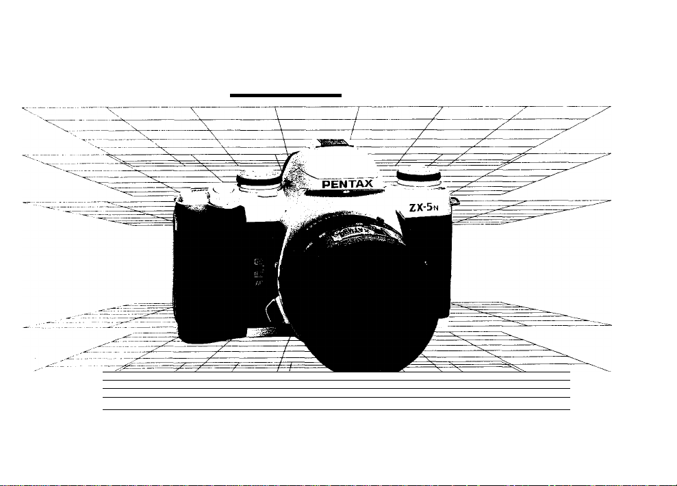
PENTAX rzx^
OPERATING MANUAL
----------------
y
y
-------
----------/----------------
-y r
^
■"/ 1
—f
--------------
^ \
\
___
\
\
\
__x=.
\
Page 2
Congratulations on your purchase of this camera and
welcome to the exciting world of Pentax autofocus pho
tography! This compact and light weight camera is an
autofocus SLR camera that offers higher levels of so
phistication and performance. Incorporating a broad
range of advanced technologies and highly accurate
automation, this camera will perform superbly for the
most exacting photographer.
Icon indicators used in this manual
Operation direction
Automatic operation
Attention
Lamp blinking
Read this instruction manual carefully to get a full ex
planation of operations before use.
The names of the camera’s working parts are listed on
the front and back flaps in this operating manual. Keep
the flaps unfolded for quick reference while reading this
manual.
Correct
Incorrect
Lenses and accessories produced by other manu
facturers are not made to our precise specifica
tions and therefore may cause difficulties with or
actual damage to your Pentax camera. We do not
assume any responsibility or liability for difficul
ties resulting from the use of lenses and accesso
ries made by other manufacturers.
o
X
Page 3
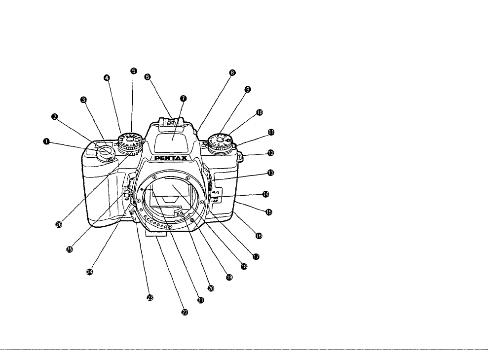
NAMES OF WORKING PARTS I
O Shutter release button
OMain switch (p.19)
@LCD panel (p.6)
OShutter dial
©Shutter dial lock button
©Hot shoe (p.77)
©Built-in flash Cp.37)
©Flash pop-up button (p.37)
©Exposure compensation dial (p.64, 76)
©lExposure compensation release button
©Drive mode dial (p.29, 44)
©Strap lug (p.12) '
©Release socket (p.63)
©Multi-function button (p.40, 42, 71)
©Back cover release lever (p.20)
©Mid-roll rewind button (p.24)
©Focus mode switch (p.34, 48)
©Mirror
®AF coupler
©Power supply contacts
©Lens mount index
©Lens information contacts
©Lens unlock button (p.17)
©AF mode switch (p-28, 65)
©Preview button (p.88)
©Metering mode switch (P.27, 68,69)
(p.64, 76)
Page 4

FOR SAFE USE OF YOUR CAMERA
Although wo have carafully designed this camera for safe operation, please be sure to follow precautions given on this page.
A\ WARNING This mark indicates precautions that, if not followed, could result in
serious injury to the operator.
/K CAUTION This mark indicates precautions that, if not followed, could result in
minor or medium injury to the operator or damage to the equipment.
A WARNING
• The electronic circuits inside the camera contain
high voltage working parts. Never attempt to disas
semble the camera yourself.
• Never touch internal parts of the camera if they be
come exposed from dropping the camera or for
some other reason, as there is danger of an electric
shock.
• Wrapping the strap around your neck is danger
ous. Make sure that small children do not get the
strap caught around their neck.
• Do not look directly at the sun through the camera,
as viewing the sun for an extended period may
damage your eyes.
• Be sure to store batteries out of the reach of chil
dren. Seek medical assistance immediately if acci
dentally swallowed.
^ CAUTION
> Do not use the flash near anyone's eyes, as it may
hurt them. Be particularly careful with the flash
around infants.
> Never try to disassemble, short or recharge the bat
tery. Also, do not dispose of the battery in fire, as it
may explode.
• Remove the batteries from the camera immediately
if they become hot or begin to smoke. Be careful
not to burn yourself during removal.
Page 5

PRECAUTIONS FOR YOUR CAMERA
Your Pentax camera is a high-precision mechanism.
Handle it with great care.
Precautions when taking pictures
• Do not use the camera where it may come in con
tact with rain, water, or any other liquid, because
the camera is not weather, water, or liquid resis
tant. Should the camera get wet from rain, splash
ing water, or any other liquid wipe it off
immediately with a dry soft cloth.
• Do not drop the camera or allow it to hit solid ob
jects. If the camera suffers a shock or impact, take
it to a Pentax service center for inspection.
• Be careful not to subject the camera to strong vi
brations, shock or pressure. Use a cushion to pro
tect the camera when carrying it in a motorcycle,
car, boat, etc.
• Condensation on the interior or exterior of the cam
era may be extremely harmful to the camera
mechanism as it may cause rust. Furthermore, if
the camera is taken from warm temperature to a
subfreezing one or vice versa, the formation of
icelets may cause damage. In such a case, put the
camera into a case or plastic bag so that any
changes in temperature difference is minimized. Do
not remove it from the bag until temperature has
stabilized.
• Regular size color prints may cut off what appears
on the extreme edges of the film frame. Compose
your picture with a margin of safety at the edges.
Precautions for storage
• Avoid leaving the camera for extended periods in
places where the humidity and temperature are
very high, such as in a car.
• Do not store the camera in a closet with moth balls
or in an area where chemicals are handled. Store it
in a place with good dry air circulation to prevent
the growth of fungus.
Precautions for proper care
• Never touch the shutter curtain or mirror with your
finger or any other object.
• Use a blower and lens brush to remove dust accu
mulated on the lens or viewfinder.
• Never use solvents such as paint thinner, alcohol or
benzene to clean the camera.
• Electrical problems may often be caused by water,
dirt or dust at points of electrical contact. Also
check for battery leakage, traces of dirt or grease,
or corrosion due to salinity or gas. If you cannot
correct the problems, have your camera inspected
at a Pentax service center. Repairs of this nature
are not covered under the terms of the warranty
and charges may be assessed.
Page 6

PRECAUTIONS FOR BAHERY USAGE
Other precautions
• The temperature range at which this camera
functions properly is 50“C to -10°C (122'F to 1
4 F).
• A camera which has been submerged in water
usually cannot be repaired. If such an accident
should occur, it is advisable to contact a Pentax
Service Center immediately.
• To maintain optimum performance, it is recom
mended that the camera be inspected every one
or two years. If the camera has not been used for
an extended period, or is being prepared for an
important photographic session, it is recom
mended that you have the camera inspected or
test shoot with it.
• Repairs deemed necessary due to usage of this
product in an industrial or commercial application
may not be covered under the terms of the
Pentax warranty.
• The PENTAX warranty provides only for the re
pair of defects in materials or workmanship.
Damage of any kind cannot be repaired at no
charge under the terms of the warranty. If the dif
ficulty is caused as a direct result of the product
being used in conditions as outlined in the
"Precautions for Your Camera" section or any
other operation contrary to the instructions out
lined in this manual, charges will be assessed and
a repair quotation will be provided.
Use two 3V lithium batteries (CR2 type).
Misuse of the battery can cause hazards such as
leakage, overheating, explosion, etc. The battery
should be inserted with the " i " and sides fac
ing correctly.
Battery performance may be temporarily hin
dered in low temperatures, but will recover in
normal temperatures.
Keep a spare battery on hand for replacement
convenience when shooting outdoors or while
traveling.
If the built-in flash is used continuously, the bat
tery may become warm, but it does not mean
that the battery is faulty: it is one of the battery's
characteristics.
Replace the batteries at the same time. Do not
mix battery brands, type or an old battery with a
new one. It may cause explosion or overheating.
Page 7

PRACTICAL SHOOTING GUIDE
Ï
Focusing -
Taking a picture when the main subject is not in
the Autofocus frame.
Changing in-focus range.
Focusing on a particular spot.
s Flash photography----------------------------------------------------
Taking a picture in low light situations.
Minimizing the red-eye effect......................................p.40
Taking a portrait when the subject is in the shade. p.81
Taking a picture of people with night scenery in
the background. ..............................................................p.82
Taking a picture in a roomy place such as a church
or reception hall...............................................................p.77
Taking a picture with the desired exposure setting.
....................................................................................p.60,64
Taking a picture in strong backlit situations with the
main subject in the shadow. ...........................................p.81
.................................................
..............................................
.......................................
Exposure modes ~
...................
p.65.66
p.56
p.65
p.37
Zooming the lens -
Making a subject larger or smaller. •p.30
Taking pictures of people in_
[C
Putting yourself into a picture. ......................................p.44
Taking a picture in strong backlit situations with the
main subject in the shade. ............................................p.81
Taking a picture of people with night scenery in
the background. ..............................................................p.82
iÆ.
Taking a picture of night scenery............................
Taking a picture of people with night scenery.
Taking a picture of a fast moving subject,
Taking a horizontally dynamic panoramic picture, ••■p.53
Taking consecutive pictures of a moving subject, p.44
various situations
Landscape photography ^
Others
..............
•p.62
•p.82
p.36,58
Page 8

TABLE OF CONTENTS
Names of working parts ........................................................Flaps
Safe use of your camera ..........................................Inside cover
Precautions for your camera
Precautions for battery usage
LCD panel indication
Viewfinder indication.....................................................................7
Easy to use! (For beginners)
Camera functions available with various lenses
How to use this operating manual
I. BASIC OPERATION (PREPARATION) 12 25
Attaching the camera strap
Loading the batteries .................................................................13
• When the battery is exhausted .............................................15
Attaching the lens ......................................................................16
Using the shutter release button
Turning on the power..................................................................19
......................................................
......................................................
....................................................................
.......................................................
.......................
............................................
.......................................................
................................................
11
12
18
Film loading ................................................................................20
Unloading film ............................................................................23
1
Adjusting the viewfinder diopter
2
6
II. BASIC OPERATION (SHOOTING) 26 - 42
Using the Programmed AE Mode
8
Using the Multi(6)- segment metering mode
10
Using the 3-point AF mode
Using the Single-Frame Drive Mode .........................................29
Using zoom lenses ....................................................................30
Holding the camera
Selecting the Autofocus Mode....................................................34
Taking a picture
Basic operation of the Built-in Retractable TTL Flash
(RTF) ..........................................................................................37
Red-eye Reduction Flash Function ...........................................40
Automatic flash (Smart Flash) function
....................................................................
.........................................................................
.................................................
.............................................
.......................................................
.....................................
............................
25
26
27
28
33
35
42
Page 9

III. ADVANCED OPERATION
Selecting a Drive Mode
• Consecutive - Frame Mode
• Self-Timer Mode....................................................................44
• Auto Bracketing Exposure Mode .........................................46
Manual focusing
• Using the Snap-in focus function
Taking a Panorama format picture ............................................53
Selecting the Exposure Mode
• Using the Programmed AE Mode........................................55
• Using the Aperture-Priority AE Mode
• Using the Shutter-Priority AE Mode.....................................58
• Using the Metered Manual Mode.........................................60
• Using the Bulb Exposure Mode
About Exposure Compensation
Spot AF Mode
• Focus Lock Function
Switching the Metering Mode ....................................................68
• Using the Memory Lock
Turning off the audible PCV signal............................................71
........................................................................
...........................................................................
.....................................
.............................................................
.................................................
........................................
...................................................
.................................
...........................................
................................................
..........................................................
.....................................................
43 - 89
Advanced operation for the built-in flash ..................................72
Compatibility of F and FA lenses with the built-in
43
44
flash............................................................................................74
Setting the film speed (ISO) manually
Using a Pentax Dedicated External Flash
Contrast-Control-Sync Flash Photography ...............................79
48
55
56
64
65
66
70
Daylight-sync shooting .............................................................81
50
Slow-speed-sync shooting.........................................................82
Accessories (Optional)...............................................................83
Camera case..............................................................................84
Effects of aperture and shutter speed
Depth of field .............................................................................87
About the preview button
62
The infrared index
IV. OTHERS..................................................................90 - 95
Troubleshooting .........................................................................90
Specifications
Warranty policy ..........................................................................94
............................................................................
...........................................................
.....................................................................
......................................
...............................
......................................
76
77
85
88
89
92
Page 10

p
Av
Tv
M
<S>
V
Q
88
Q_
ISO
BBbo
LCD PANEL INDICATION
Programmed AE (p.55)
Aperture-Priority AE (p.56)
Shutter-Priority AE (p.58)
Metered Manual Mode (p.60)
Red-Eye Reduction Flash Indication (p.40)
Flash Information (p.37, 39)
Automatic flash function information (p.42)
(Smart flash information)
Frame Counter (p.23)
Film Status Information (p.22, 23)
Battery Exhaustion Warning (p.15)
Audible PCV Signal (p.71)
Film Speed Setting Signal (p.76)
Film Speed Information (p.76)
LCD (Liquid-Crystal Display)
When the LCD is exposed to high temperatures over ap
proximately 60°C it may blacken, but when the tem
perature normalizes, it should return to normal.
Page 11
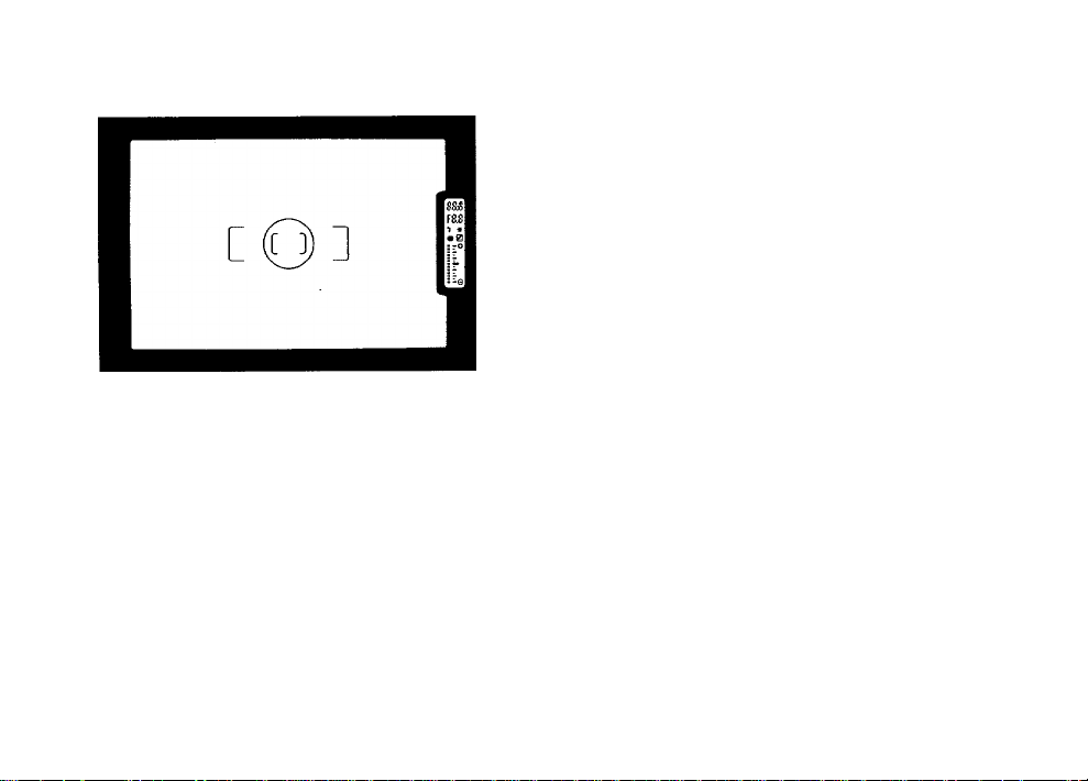
3-point AF Frame (p.35)
C D
F
*
O
Spot AF Frame (p.65)
n n I"
Shutter Speed (p.55, 57, 59,61)
O COI>
n n
Aperture Value (p.55, 57, 59, 61)
>J. L<
Flash Status Information (p.37, 39)
In-Focus Indicator (p.35)
Memory lock indicator (p.70)
Exposure Compensation (p.64)
e
O
Bar Graph (p.61,64)
: Spot metering area (p.68)
VIEWFINDER INDICATION
When the format is switched to panorama, the view
finder switches to the horizontal panorama format
frame. For details on panorama format picture taking,
see page 53.
Page 12
EASY TO USE (For beginners)
1. Loading the batteries
Open the battery chamber cover by using a coin.
Load two batteries (CR2 type) according to the mark
ings ( • , ) in the battery chamber. (See page 13.)
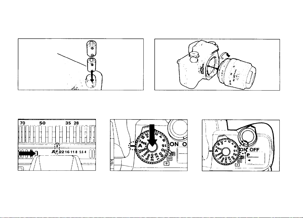
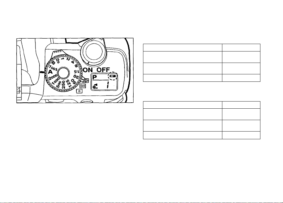
3. Positioning the aperture ring 4. Setting the shutter dial
While holding down the apertureA lock button, turn the lens aper
ture ring to the [ A : position.
(See page 26.)
While holding down the shutter
dial lock button, turn the shutter
dial to [ A ] . (See page 26 ). The
exposure mode will be set in the
Programmed AE Mode.
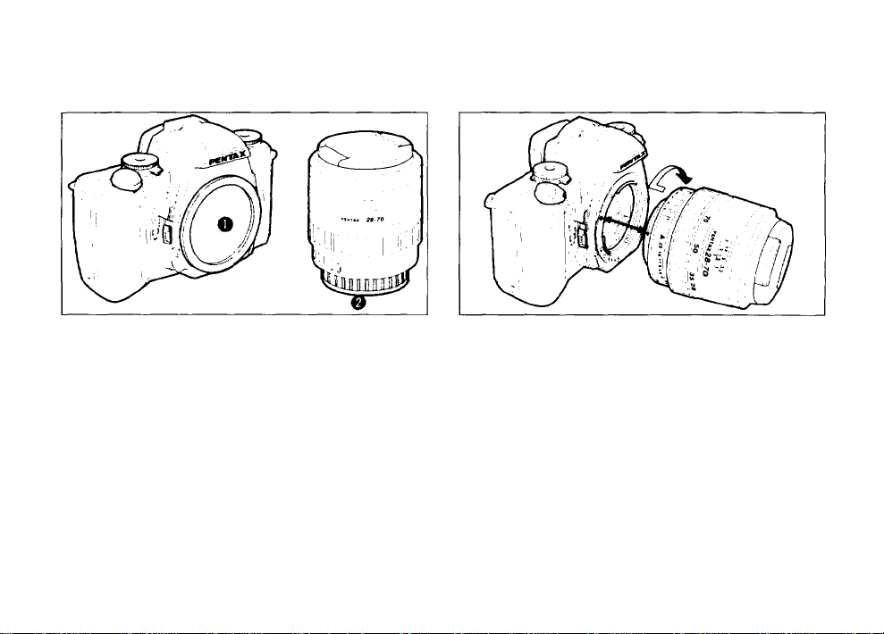
2. Attaching the lens
Align the red indexes on the lens and camera. Turn the
lens to the right until it seats with a click. (See page
16.)
5. Turning on the power
Set the main switch to i ON
page 19.
. See
Page 13
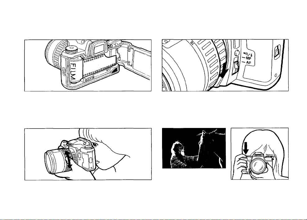
6. Loading film 7. Selecting the Autofocus Mode
Open the back cover, insert a roll of film, align the end
of the film leader with the red mark, and close the back
cover. The film should advance to the first frame auto
matically. (See page 22.)
8. Composing the scene with the zoom ring
While looking through the viewfinder, turn the zoom
ring to the right or left until you obtain the desired com
position. (See page 30.)
Set the focus mode switch to [ AF ]. (See page 34.)
9. Focus on the subject and shoot
Focus [ C D ] on the subject. Depress the shutter re
lease button halfway to lock focus, and then depress it
fully to take a photo. (See page 35.)
Page 14

m
CAMERA FUNCTIONS AVAILABLE WITH VARIOUS LENSES
Function Lens
Autofocus (Lens only)
Manual focus (with FI) *2
Power zoom
Image size tracking
Zoom clip
Auto zoom effect
Programmed AE 0*5
Aperture-Priority AE
Shutter-Priority AE
Metered Manual
Programmed TTL Auto Flash
TTL Auto Flash
Multi(6)-segment metering
Approx, f-stop indication
(Lens with AF Adapter 1.7X)
[Mount type]
(with Matte field)
FA l«ns
[K«]
o
0*3
o
0*4
X X X
X X
X X X
C
0*5
0
F lens
[K»]
....o.........
0*3 0*3
o
X
0*5
o
O'* 5
Q.
Q
c O'
0
A lens
[K.]
X
0*1
o
X X X
X X X
O'
0 X X
O'
Q
01
X
Notes;
* 1. Lenses with a maximum aperture of f/2.8 or larger. (See AF Adapter operating manual.)
* 2. Manual focusing using the focus indicator (FI) (O) in the viewfinder.
* 3. Lenses with a maximum aperture of f/5.6 or larger.
* 4. Pentax-FA zoom lenses with the power zoom contacts only.
* 5. Exception of Pentax-FA Soft 85mm f/2.8 and FA-soft 28mm f/2.8,
* 6. The center-weighted metering or Spot metering is used instead of the multi-(6) segment metering mode.
M lens
[K]
X
0*1
0’*3
o
X X
X X
X X
X
X ♦ 6
X
S lens
[Screw]
X
X
X
C'
o
l^'l
X
X * 6
X
Page 15
HOW TO USE THIS OPERATING MANUAL!
This manual is organized into the following sections, allowing you to optimize the use of the camera:
r-<
I. BASIC OPERATION
(PREPARATION) Page 12 -25
1___________^________________________
1. ADVANCED OPERATIONS
Page 43-89
1_____________________________________
Q
n. BASIC OPERATION
(SHOOTING) Page 26 - 42
If you want to begin taking pictures with this new camera as soon as possible, read section I and II, "BASIC
OPERATION (PREPARATION)" and "BASIC OPERATION (SHOOTING)."
These sections introduce only the basic functions of this camera. More detailed information can be found in sec
tion III and section IV.
Page 16
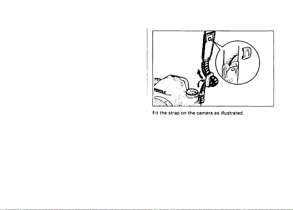
AHACHING THE CAMERA STRAP
CD
>
o
o
-0
m
JO
>
TJ
>
JO
>
o
z
I . BASIC OPERATION
(PREPARATION)
There is a pocket on the strap so you can store the
finder cap, release socket cover, hot shoe cover or
any other small accessory as illustrated.
Page 17
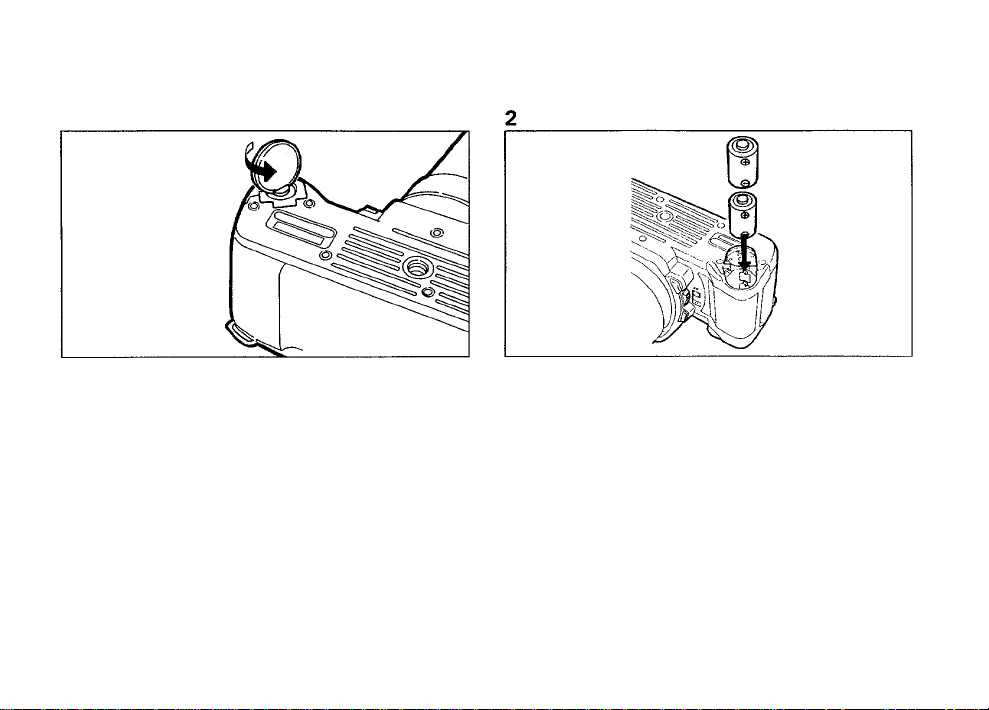
(2) LOADING THE BATTERIES
1. Open the battery chamber cover by using a coin,
etc. as shown in the illustration.
2. Load two 3V lithium batteries (CR2) or equivalent
as shown in the illustration.
Misuse of the battery can cause hazards such as leak
age, overheating, explosions, etc. The battery should
be inserted with the " + " and " —" sides facing cor
rectly.
00
>
o
o
•V
m
30
>
H
o
z
30
m
■D
>
30
>
H
o
z
Page 18
>
o
o
'V
m
9
>
H
o
z
9
>
9
>
O
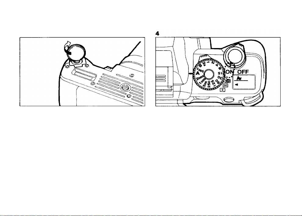
3. Turn the battery chamber cover screw in the direc<
z
tion of the arrow to lock it securely.
4. Set the main switch to [ ON ] and check that the
LCD panel shows the information as shown above.
When the battery is replaced, all camera settings re
main unchanged except the audible PCV signal
switching, red-eye reduction flash function and auto
matic flash function of the built-in flash.
The optional" AA-Battery Pack Fg" is also available
for this camera instead of using the lithium batteries.
The LCD display as shown above is given as an exam
ple and may be different if a lens is attached.
Page 19
• Low Battery Warning
When the batteries are nearly exhausted, the battery
symbol [*^] appears on the LCD panel to warn you.
Replace the batteries as soon as possible. See page 13.
• When the low battery warning [ca] starts blinking,
the shutter cannot be released and all indicators in
the viewfinder disappear. Replace the battery as soon
as possible. See page 13 for replacing the batteries.
• Replace two batteries at the same time. Do not mix
battery brands, type or an old battery with a new one.
It may cause explosion or overheating.
Battery Life (using 24-exposure film rolls at 20°C/
68° F)
General existing light photography
Flash photography
(using flash 50% of the times)
Flash photography
(using flash 100% of the times)
Bulb exposure time
Battery Life (using 24-exposure film rolls at 10°
C/14°F)
General existing light photography
Flash photography
(using flash 50% of the times)
Flash photography
(using flash 100% of the times)
Bulb exposure time
CR2 batteries were used under Pentax testing condi
tions. Actual battery life and performance may vary
drastically depending on usage of Autofocus, Power
zoom and external conditions such as temperature and
freshness of the battery.
about 120 rolls
about 20 rolls
about 12 rolls
about 8 hours
about 30 rolls
about 15 rolls
about 5 rolls
about 2 hours
OD
>
«
o
-D
m
3D
>
o
z
3D
m
5
3D
>
Page 20
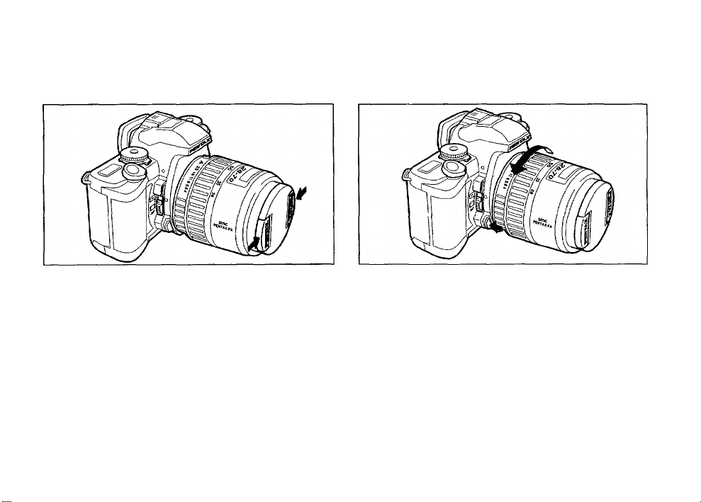
(3) ATTACHING THE LENS
>
o
o
“0
m
3
>
o
3
3
m
3
>
3
>
H
o
. Remove the body mount cap O and rear lens cap
z
0 as shown in the illustration.
The body mount cap is designed to protect the cam
era against scratches and dust at the factory. For
storage, the optional accessory "Body Mount Cap K"
is available.
2. Align the red dots on the camera and lens mount,
attach the lens to the camera body, and turn it fully
to the right until you hear a click.
• Ensure that the camera's main switch is in the "OFF!
position before attaching an FA zoom lens to prevent
unexpected operation of the lens.
Page 21
3. To remove the front lens cap, squeeze the tabs on
both sides in the direction of the arrow.
•
• We assume no responsibility nor liability for damages
resulting from the use of lenses made by other manu
facturers.
• The camera body and lens mount incorporate lens in
formation contacts and an AF coupler. Dirt, dust, or
corrosion may cause damage to the electrical system.
Clean the contacts with a soft, dry cloth.
* How to remove
To remove the lens, turn it to the left while depressing
the lens unlock button.
• To protect the contacts and AF coupler of the lens
against damage after removal, be sure to set the lens
down with the mount side facing upward.
>
o
o
31
>
T3
3)
>
m
■D
>
X
Page 22

(4) USING THE SHUHER RELEASE BUHON
The shutter release button has two positions.
Depressing it down halfway (first position) turns on the
exposure meter and autofocus system. Depressing it
>
fully (second position) releases the shutter. When tak
W
o
ing a picture, depress the shutter release button gently
o
to prevent camera shake.
■p
ni
3
>
• To prevent camera shake, depress the shutter release
button gently.
• Before loading a roll of film, slowly depress the shut
ter release button to learn where the first position is.
• The LCD indication stays on for about 10 seconds
>
after the button is released from the halfway position.
3
>
Depressing the shutter release button down halfway
H
keeps the LCD indicator on.
o
z
Not pressed Pressed halfway
down
(first position)
Pressed fully
down
(second position)
Page 23

(5) TURNING ON THE POWER
1. The power is turned on when the main switch is set
to [ON].
2. The power is turned off when the main switch is
set to [ OFF ].
When not in use, ensure that the main switch is set to
[OFF].
00
>
CO
o
o
m
9
>
-I
O
z
9
3
m
?
9
>
o
z
Page 24
(6) FILM LOADING
We suggest that you first operate the camera with no
film loaded to become familiar with its operations.
D
>
«
Automatic film speed setting
O
This camera is designed to use DX-coded films with ISO
o
ratings from 25 to 5000.
T>
m
3
)
>
• When DX-coded film is used, the correct film speed is
H
automatically set for the camera. If you use a non-DX
o
z
coded film, you can set the film speed manually. See
page 76.
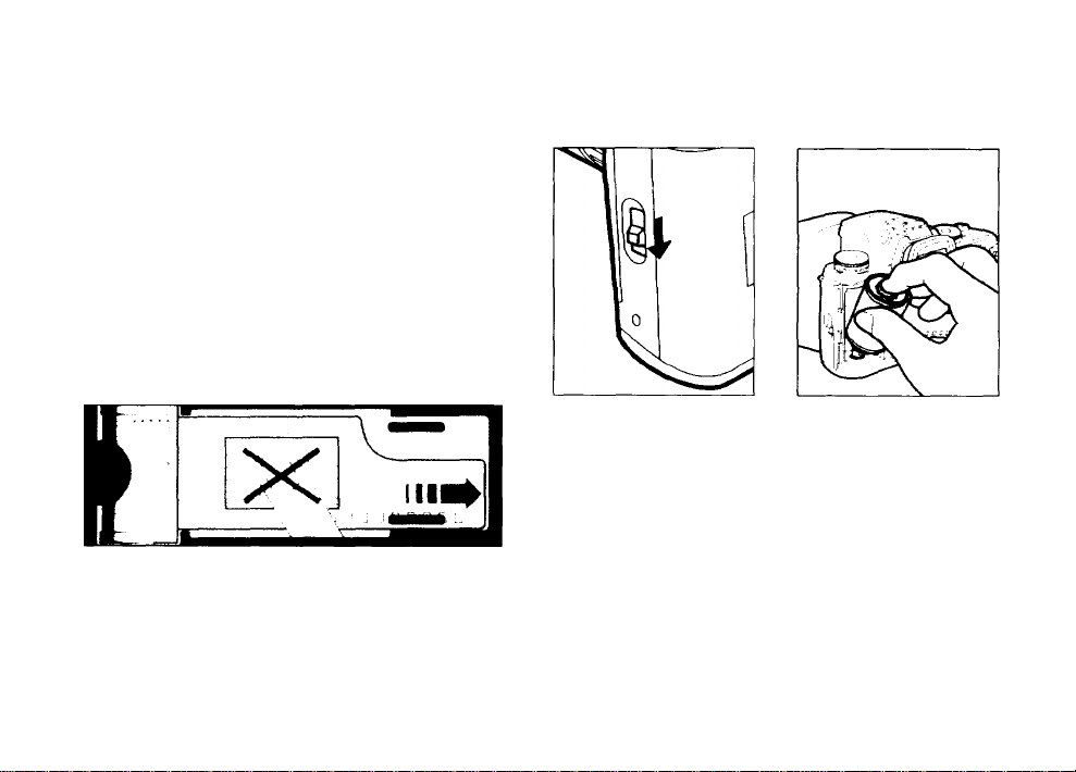
• Before loading film for the first time after purchase,
■0
>
open the back cover and remove the protective card
31
>
DO NOT TOUCH THE SHUTTER CURTAINS.
1. To open the back cover, slide the back cover re
lease lever in the direction of the arrow.
2. Place the film cartridge in the film chamber as
shown in the illustration.
• Always load and unload film in the shade or by using
your body to shade the camera
Page 25
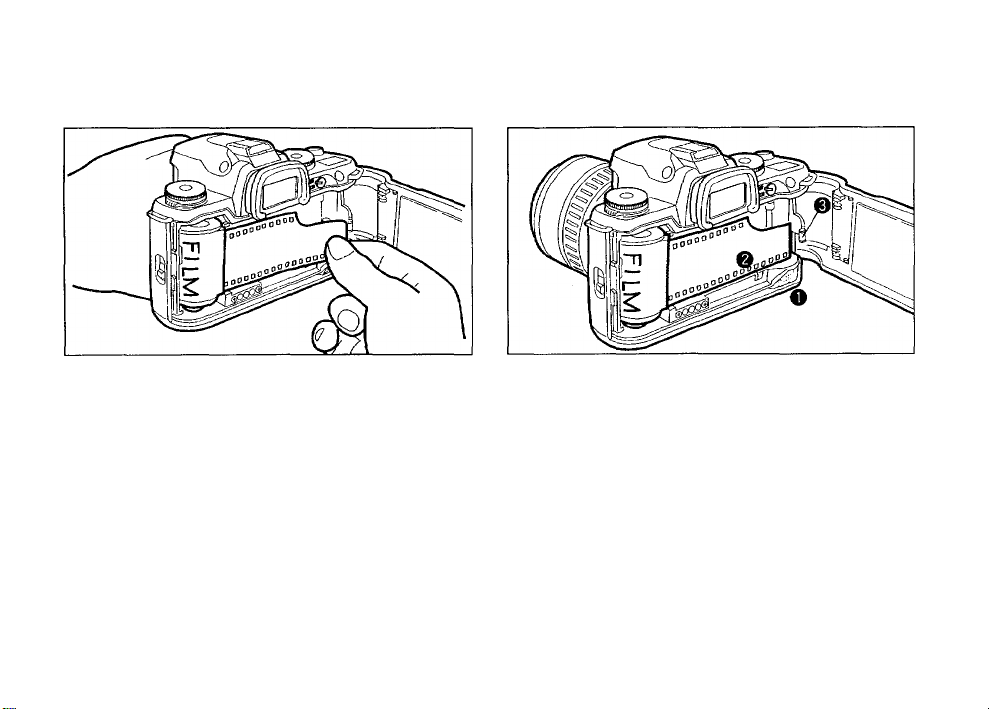
3. As shown in the illustration, pull the film leader out
only far enough to reach the take - up spool.
4. Align the film leader with the film leader end mark
O as shown.
OD
>
o
o
■o
m
3
>
H
o
z
3
m
■D
>
39
>
o
z
)
THE SHUTTER CURTAINS ARE FINE-PRECISION
MATERIAL. DO NOT TOUCH THEM WITH YOUR
FINGERS OR ANY OTHER OBJECT WHILE LOADING
FILM.
If you have pulled out too much film, push it back Into
the cartridge to reduce the slack.
The DX information pins in the film chamber are used
to read film speed. Keep them clean and free from
scratches. To remove smudges, wipe them gently
with a soft, dry cloth.
• Make sure that the film perforations properly engage
on the sprocket teeth
• Make sure that the film leader is positioned under the
film retainer 0 as shown in the illustration.
Page 26
Film loaded with slack No!
OB
>
o
o
*0
m
JO
>
Film loaded flat Yes!
5. Close the back cover and set the main switch to
the [ ON ] position. The film automatically ad
vances to the first frame.
If the film Is not loaded
properly. [ Q_ f ] on
the LCD panel blinks,
indicating that the film
is not loaded properly.
Open the back cover
and load the film once
again.
• Check that [ / ] and [Q_ ] are displayed on the LCD
panel.
• The film counter indication advances one each time
the shutter is released.
Page 27
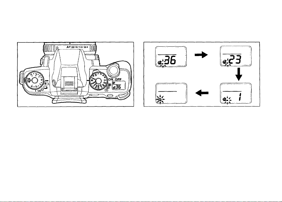
(7) UNLOADING FILM
1. The film automatically rewinds at the end of the
roll.
• During rewinding, [ — ] blinks on the LCD panel, indi
cating that the film is being rewound, the exposure
counter counts frame numbers in reverse.
• Never open the back cover until the whole film roll is
completely rewound.
• When removing the film from the camera, protect it
from exposure to direct sun light.
2. When the film is fully rewound, only [Q] blinks on
the LCD panel.
09
>
o
o
*0
m
jj
>
7)
m
•V
>
30
>
H
o
z
Page 28
m
>
at
o
O
■o
in
a
>
o
z
■ V
>
73
>
A roll of 24-exposure film takes about 1 3 seconds to
rewind.
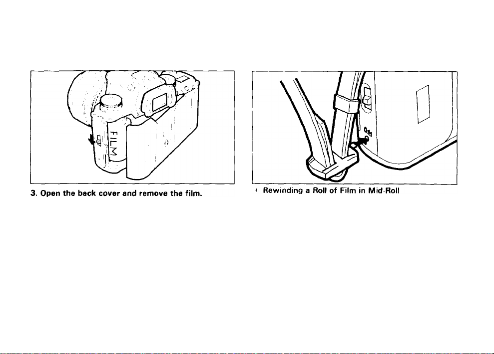
Before opening the back cover, check that I Q is
blinking.
When the camera is not in use, set the main switch to
the [ OFF . position.
The shutter may be released a frame or more after
the specified number of frames have been used as in
dicated by the number of frames on the film cartridge
However, those extra frames may be lost in process
ing. When you take important pictures, rewind the
film when the film reaches the number of frames indi
cated on the film cartridge.
If you wish to unload the film before exposing all the
frames, use this function
Set the main switch to the ' ON position, and then de
press the mid-roll rewind button by using the protruding
part of the strap clamp.
• Do not depress the button with an object having a
sharp tip.
• Before opening the back cover, check that Q is
blinking.
Page 29
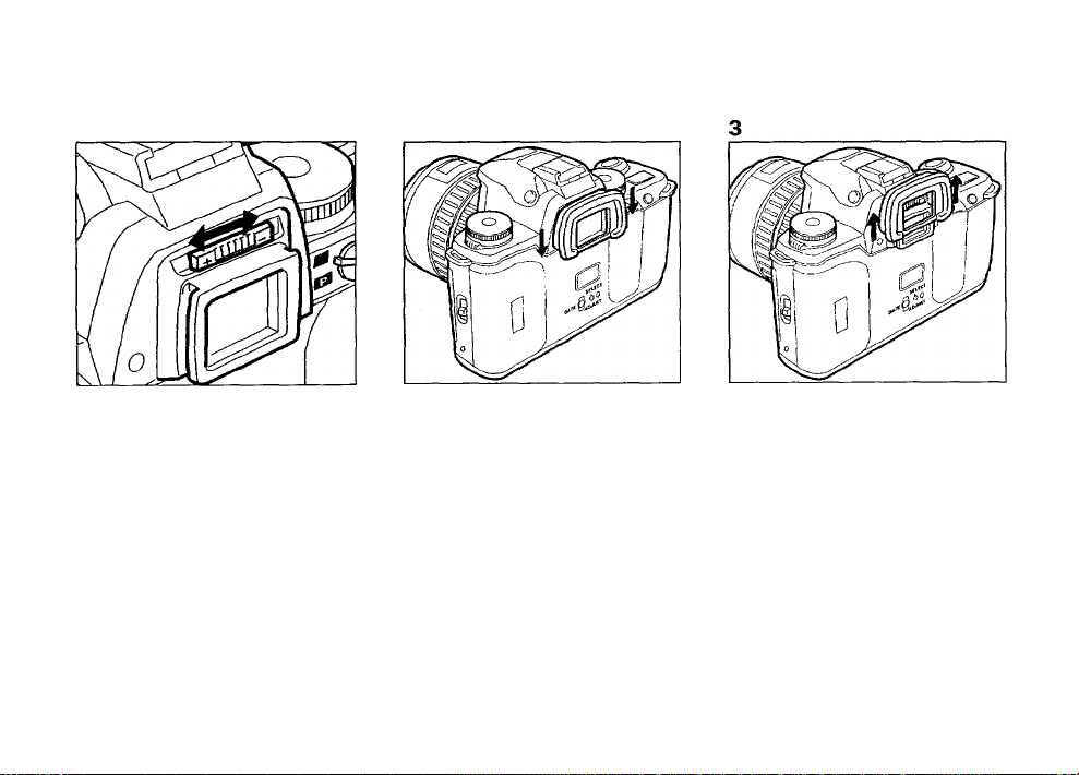
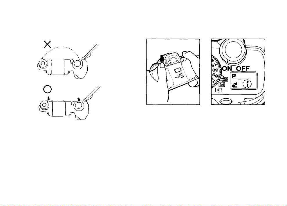
(8) ADJUSTING THE VIEWFINDER DIOPTER
1. Aim the camera at a bright subject. While looking
through the viewfinder, move the diopter adjust
ment lever to the left or right until the autofocus
frame [C 3] appears in the sharpest focus.
2. To attach the Eyecup Fg, slide it down the grooves
on both sides of the viewfinder.
3. To detach the Eyecup Fg, push it up in the direction
of the arrow.
The diopter adjustment range is
(diopters).
-1.5D to -2.5D
>
o
o
"0
m
33
>
H
o
z
■ V
>
33
>
-i
Page 30
II. BASIC OPERATION (SHOOTING) (D US ING TH E P RO GRAM ME D A E M ODE
Purpose
For easy picture taking, use this mode. In the
Programmed AE mode, the camera automatically se
lects the best combination of aperture and shutter
speed setting allowing you to take pictures by simply
depressing the shutter release button.
How to set
1. Turn the lens aperture ring to the [ A ] position as
shown in the illustration.
To move the lens aperture ring to the [ A ] position,
turn the aperture ring while holding down the
aperture-A lock button on the lens. The lens aperture
ring can be released from the [ A ] position in the
same manner.
2. Turn the shutter dial to [ A ] while holding down
the shutter dial lock button. The shutter dial can be
released from [ A ] in the same manner.
• ( P : appears on the LCD panel to indicate that the
Programmed AE Mode is set.
• See page 56, 58 and 60 for other available exposure
modes.
Page 31

(2) USING THE MULTI (6)-SEGMENT METERING MODE
MULTI(6)-SEGMENT METERING
This camera incorporates a high-precision six-segment
TTL metering system. Light values are measured in six
segments within the image field, enabling an optimal ex
posure to be made under a variety of lighting condi
tions. With conventional averaged metering systems,
underexposure of the subject results from the bright
ness of the background affecting the overall metering.
With multi(6)-segment metering, the camera records
the brightness in six zones within the image field and
uses these measurements to choose an exposure that
will not underexposed the subject. The multi(6)segment metering system also calculates exposure val
In the multi(6)-segment metering mode, the metering
system automatically measures light in six different
zones, enabling proper exposure value in a wide variety
of normal and adverse lighting conditions, such as a
backlit condition.
1. Set the metering mode switch to [ SB ].
• When a lens other than an A, F or FA lens is attached,
use either center-weighted metering or spot meter
ing. The multi-segment metering mode cannot be set.
See page 68 for selecting the metering mode.
ues for a scene to automatically compensate for highcontrast and other difficult lighting conditions. Even a
beginner can achieve excellent results with ease.
os
>
CA
O
o
TJ
m
OS
>
H
o
z
»
X
o
o
z
o
Page 32

(3) USING THE 3-POINT AF MODE
QD
>
W
o
o
•V
m
3
>
H
o
z
This camera incorporates 3-point autofocus system.
The subject will be focused properly even if the main
X
o
subject is slightly off the center of the AF frame.
o
c Set the AF mode switch to C 3'.
• The Spot AF Mode is also available in this camera.
See page 65 for details.
Page 33

(4) USING THE SINGLE-FRAME DRIVE MODE.
One picture is taken each time the shutter release but
ton is depressed.
Set the drive mode dial to [ □].
The Consecutive-Frame Mode, Self-Timer Mode and
Auto Bracketing Mode are also available in this camera.
For details of each drive mode, see page 43.
03
>
w
o
O
T3
m
30
>
o
z
v>
z
o
o
H
z
o
Page 34

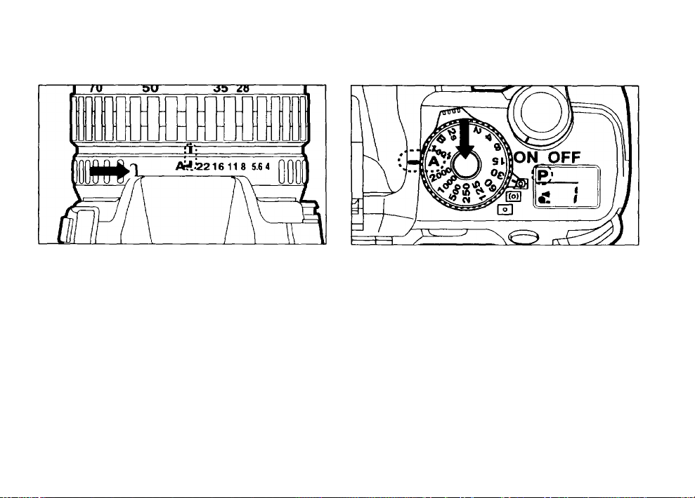
Wide angle
(5) USING ZOOM LENSES
Using the zoom function makes the subject appear
larger (telephoto) or smallerCwide angle) in the view
finder. Turn the zoom ring to the desired position and
depress the shutter release button to take a picture.
• The smaller the number shown in the zoom scale win
dow, the wider the angle. Converselv. the larger the
number, the more magnified the image appears.
Page 35

Turning the zoom ring to the right makes the subject ap
pear larger (telephoto) and turning it to the left makes
the subject appear smaller (wide angle).
Using the manual zoom function with an FA zoom lens
attached
Pull the power zoom ring toward the camera body until
the words [POWER ZOOM] are hidden.
CD
>
w
o
o
JO
>
CO
X
o
o
H
z
o
Page 36

IS
>
IS
o
O
D
m
3
>
H
o
z
CO
Using the Puwer Zoom Function
X
O
1. Push the power zoom ring forward until the words
o
POWER ZOOM appear beneath the power zoom
ring.
2. Turning the power zoom ring to the right brings the
subject closer (telephoto) and turning it to the left
makes the subject smaller (wide angle). To stop
zooming, release the power zoom ring.
If a power zoom lens Is attached, three zooming
speeds are available. Turning the power zoom ring
fully to the right or left, zooms the lens quickly.
Turning it slightly gives you slow operation. At an in
termediate position, the lens zooms at medium speed.
Zooming the lens with the power zoom function auto
matically focuses the lens on the subject. However,
for final focusing, depress the shutter release button
halfway down to focus the subject.
When the main switch is set to [ OFF _ while a
Pentax-FA zoom lens is in use, the lens automatically
retracts to its shortest physical length.
An FA zoom lens without
the power supply contacts
are shown in the illustration
does not have the power
zoom function (ie: FA28 70mm f 4 AL lens).
Page 37

(6) HOLDING THE CAMERA
Camera held horizontally
For best results, be sure to hold the camera correctly
as shown in the illustrations.
Hold the camera firmly, with your left hand supporting
the camera and lens as shown in the illustrations.
While taking a picture, hold your breath and gently de
press the shutter release button. (Sudden force on the
shutter release button will cause camera shake, making
the picture blurred.)
Camera held vertically
To reduce camera shake, support your body or the
camera on a solid object - a table, tree, or a wall for in
stance.
Although there are individual differences among pho
tographers, in general the shutter speed for a hand
held camera is the inverse of the focal length. For ex
ample, 1 /50 of second when the focal length is
50mm, and 1/100 of second when it is 100mm. A
tripod should be used for shutter speeds slower than
this.
When using an ultra-telephoto lens, a tripod that is
heavier than the total weight of the camera and lens
is recommended to avoid camera shake.
>
K
CJ
O
■0
m
31
>
o
u>
X
o
o
H
z
o
Page 38

(7) SELECTING THE AUTOFOCUS MODE
For autofocus operation, set the focus mode switch to
[ AF],
When you depress the shutter release button halfway
down, the lens automatically focuses.
• See page 48 for manual focusing.
Page 39

(8) TAKING A PICTURE
Set the focus mode switch to [ AF ].
1. Focus on the subject with the 3-point AF frame
[C D] indicated in red in the photograph. When the
shutter release button is depressed halfway down,
the lens automatically focuses.
2. When the subject is in focus, the focus indicator
[ O] lights up and an audible PCV beeping signal is
emitted.
• As this camera incorporates 3-point autofocus sys
tem, the subject will be focused properly even if the
subject is slightly off the center of the AF frame.
• Select the Spot AF Mode to focus on a particular spot
in the frame. See page 65.
• When the shutter release button is depressed half
way down, the shutter speed and aperture setting are
displayed in the viewfinder and on the LCD panel.
• When [^ ] blinks in the viewfinder and on the LCD
panel, the use of the built-in flash is recommended.
For more details on the built-in flash, see page 37.
• The audible PCV signal can be turned off. See details
on page 71.
• During autofocus operation, the focusing ring should
not be obstructed with your fingers, hands, or any
other object.
The focus indicator [O] blinks when the camera is not
able to obtain proper focus for one of the following rea
sons.
1. The subject is too close. Adjust the camera-tosubject distance.
2. The subject is difficult to autofocus. See "HARD-TOAUTOFOCUS" on page 51.
n
>
o
o
-0
m
X
>
cn
X
O
O
Page 40

3. To release the shutter, gently depress the shutter re
lease button fully.
• The shutter cannot be released if the subject is out of
focus.
• Depress the shutter release button halfway down.
09
While [O] is on, the camera-to-subject distance is
>
fixed (focus lock). To refocus on another subject, lift
M
O
your finger off the shutter release button.
O
• When the drive mode switch is set to the
•O
m
Consecutive-Frame Mode [ Oil ], the lens focuses
a
>
each time you release the shutter.
H
• When using the SMC Pentax-F Soft 85mm f/2.8
O
Z
lens, set the aperture between f/2.8 and f/4.5. See
M
page 52 for details.
Z
O
O
Predictive Autofocus Mode
When the camera senses subject movement during the
autofocus operation, the camera will automatically
switch the focus mode to the predictive autofocus
mode to measure the speed of a moving subject, and
predict where it will be at the moment of shutter release
to maintain sharp focus on the subject.
• If the subject is moving too fast, the shutter may not
be released.
Page 41

(7) BASIC OPERATION FOR THE BUILT-IN RETRACTABLE HL FLASH (RTF)
A
---
IP
Q.
----
Li
____
’
0
The Flash-Recommended Indicator
If the built-in flash is recommended, the flashrecommended indicator [^] starts blinking in the view
finder and on the LCD panel when the shutter release
button is depressed halfway down.
• In the Programmed AE Mode and the AperturePriority AE Mode, the flash-recommended indicator
[ appears when you attempt to photograph a sub
ject in low light, or in a backlit situation. In the
Shutter-Priority AE Mode, the flash-recommended in
dicator appears only when attempting to photograph
a subject in a backlit situation.
Using the built-in flash
If [ 0 ] is displayed on the LCD panel, it indicates that
the automatic flash function is set. Delete it from the
LCD panel. See page 42 for more details.
1. Push the flash pop-up button to activate the flash.
• The flash unit starts charging automatically. When it
is fully charged, ] appears on the LCD panel. When
the shutter release button is depressed halfway
down, ] also appears in the viewfinder.
• When the shutter release button is depressed half
way down, the shutter speed and the aperture setting
appear in the viewfinder.
• When the built-in flash is used, using a lens hood is
not recommended as it may obstruct the path of the
light coming from the flash, causing vignetting in the
picture corners.
D)
>
m
o
O
TJ
m
3>
>
H
o
z
m
X
o
o
Page 42

flash unit discharges. After using the flash, retract
the built-in flash by pressing it down into the cam
era body.
If the built in flash is used continuously, the battery
may become warm, but it does not mean the battery
is faulty; it is one of the battery's characteristics.
With the built-in flash poppep-up, an external flash
cannot be attached to the hot shoe. If you would like
to use an external flash together with the built-in
flash, see the flash connections on page 77.
The shutter cannot be released until the flash is fully
charged.
Flash effective range for Programmed TTL Auto Flash
with ISO 100 (400) film used
Maximum Lens Aperture
f/1.4
f/2
f/2.8
f/3.5,f/4.7
f/5.6
Effective Ranoe
approx. 0.8 - 3.9m (0.8- 5.6m)
2.6 - 12.8ft (2.6-18.4ft)
approx. 0.8 - 3.3m (0.8- 4.8m)
2.6 - 10.8ft (2.6-15.7ft)
approx. 0.7 - 2.8m (0.7- 4.0m)
2.3-9.2ft (2.3-13.1ft)
approx. 0.7 - 2.4m (0.7- 4.0m)
2.3 - 7.9ft (2.3-13.1 ft)
approx. 0.7 - 2.0m (0.7- 4.0m)
2.3-6.6ft (2.3-13.1ft)
The effective range of the flash depends on the maxi
mum aperture of the lens in use. A lens with a maximum
aperture of f/1.4 is marked as 1:1.4 on its barrel.
• This effective range table is only applicable when the
exposure mode is set at the Programmed AE mode.
When any other exposure mode is used, see page 73.
• The minimum effective range is always 0.7m (2.6 ft)
even if a lens with a maximum aperture f/2.8 or
smaller is in use. When a subject is shot at a distance
closer than 0.7m (2.6 ft), the correct exposure can
not be obtained, and you will see vignetting in the pic
ture corners.
Page 43

Inappropriate lens warning when the built-in flash is
used
When using an inappropriate F-orFA- lens, [^] will ap
pear in the viewfinder and [ 4 ] on the LCD panel when
the shutter release button Is depressed halfway down.
For more details on COMPATIBILITY OF F AND FA
LENSES WITH THE BUILT-IN FLASH, see page 74.
• Taking a picture while this warning is displayed may
cause vignetting in the picture corners or semi
circular vignetting at the bottom of the picture.
• Keep in mind that when lenses other than an F or FA
are used, this warning will not appear.
Depressing the multi-function button with the built-in
flash popped up
At each press of the multi-function button, the flash
mode on the LCD panel switches as shown in the chart.
Normal Red-eye reduction Automatic flash Red-eye reductin
(p.37) (p.40) (Smart flash) +
(p.42) Automatic flash
When the built-in flash is retracted, depressing the
multi function button switches the audible PCV signal
ON and OFF.
n
>
o
o
■V
tn
JJ
>
o
0>
X
o
o
-t
z
a
Page 44

o
>
(0
o
O
■o
m
31
>
CO
Red-eye Reduction Flash Function
z
O
This camera includes a red-eye reduction flash function,
O
which reduces the red-eye phenomenon utilizing
preflash. In this mode, the preflash is discharged just
before the shutter is released which reduces the diame
ter of the pupil of the eye. Then the main flash is dis
charged while the pupils are smaller, which in turn
reduces the red-eye effect.
How to Set
1. Push the flash pop-up button to activate the flash.
2. Depress the multi-function button until [<■> ] ap
pears on the LCD panel.
• To set the red-eye reduction function, depress the
multi-function button only when the built-in flash is in
the popped up position. If the multi-function button is
depressed with the built-in flash is in the retracted po
sition, the PCV signal mode will be switched.
How to cancel
With the built-in flash popped up, depress the multi
function button until [<■>] disappears on LCD panel.
Page 45

When the AF500FTZ is attached and the slave flash
function is in use, the Red-eye reduction flash func
tion cannot be used as the slave flash is discharged
when the preflash of the built-in flash is discharged.
When only a dedicated flash is in use and is dis
charged, the red-eye reduction display on the LCD
panel is disregarded.
About Red-eye Phenomenon
Shooting portraits with flash in a dark environment
often causes a subject's eyes to turn out reddish in the
print. This phenomenon, commonly known as "Red-
Eye", is caused by the reflection of the electronic flash
in the retina of your subjects eye. It can be reduced by
taking the photo in a brighter light condition or by
shooting with a wider angle lens at a closer distance, or
by employing the red-eye reduction flash feature. When
using a Pentax dedicated flash unit off the camera, it
may also help to position the flash as far away from the
camera as possible.
ts
>
(n
o
o
7J
>
U1
X
o
o
Page 46

AUTOMATIC FLASH FUNCTION(SMART FLASH FUNCTION)
This is a convenient flash mode that the flash dis
charges only when it is necessary even if the flash is in
the popped-up position.
The Automatic Flash Function varies depending on
the selection of the camera's metering mode and the
exposure mode as follows:
Exp osu re
Mode
Pro gramed
AE
Oth er
Exp osu re
Modes
Multi-segm ent
Aut omatic dis
cha rge in low
ligh t and bac klit
situ atio ns
For ced emissio n
Meterin g M ode
Cen ter-weighte d Spo t
Aut omatic dis
cha rge in low ligh t
situ atio n
For ced emissio n
Aut omatic
discharge in
low ligh t
situ atio n
For ced emis
sion
How to set
1. Push the flash pop-up button to activate the flash.
2. Depress the multi-function button until [ B ] ap
pears on the LCD panel.
• Depress the multi-function button with the built-in
flash popped-up position. If the button is depressed
with the built-in flash retracted position, the PCV
mode will be switched.
How to cancel
With the built-in flash popped up, depress the multi
function button until [ B ] disappears from the LCD
panel.
Page 47

m. ADVANCED OPERATIONS
(1 ) S E L E C T I N G A D R I V E M O D E
This drive mode has a total of three drive modes as
shown.
Types of Drive Modes
Single-Frame Mode
[ □] : One picture is taken each time the shutter re
lease button is depressed.
Consecutive-Frame Mode
[ Oil] : Pictures can be taken consecutively while hold
ing down the shutter release button.
See page 44.
Self-Timer Mode
[ 0 ] : A picture will be taken with a 12-second-delay.
See page 44.
Auto Bracketing Exposure in 1/2 EV step
[1/2] : Three pictures are taken consecutively with dif
ferent exposure levels in 1/2 EV step incre
ments. See page 46.
Auto Bracketing Exposure in 1 EV step
[ 1 ] : Three pictures are taken consecutively with dif
ferent exposure levels in 1 EV step increments.
See page 46.
>
o
<
>
o
TJ
in
31
>
H
5
z
vt
Page 48

o
How to set
z
CO
Set the drive mode dial to [Ql ] ■
• The camera focuses on the subject frame by frame in
this mode.
• The shutter cannot be released while the built-in flash
is being charged.
2. Self-Timer Mode
The self-timer mode delays the shutter release, and is
useful for taking group shots that include the photogra
pher. The shutter will be released about 12 seconds
after the shutter release is depressed.
How to set
1. Set the drive mode dial to [ci)j.
Page 49

2. Focus on the subject first using the autofocus
frame and by depressing the shutter release but
ton halfway down. Then depress the shutter re
lease button fully.
• The shutter will be released about 12 seconds later.
• When the self-timer is in operation, the audible PCV
signal is heard and the rate increases for the last two
seconds.
•
How to cancel
To cancel the self-timer operation after it has been acti
vated, move the drive mode dial to a position other than
[0].
i Underexposure may occur if light enters the view
finder during self-timer operation. If you intend to
move away from the viewfinder, attach the supplied
finder cap as shown in the illustration.
* When using accessories such as the Findercap, re
move the Eyecup Fg. The Eyecup Fg comes from the
factory fitted to the camera's viewfinder accessory
grooves.
>
o
<
>
z
o
Itl
o
o
■D
m
>
o
Page 50

>
o
<
>
z
o
m
Auto Bracketing Exposure Mode
o
When you take a picture that requires exposure com
o
pensation it may be difficult to obtain the correct expo
m
9
sure. Use this mode to make three different bracketed
>
exposures with different exposure levels.
o
z
(A
1. Auto Bracketing Exposure in 0.5 EV step
Set the drive mode dial to [ 1X2 ].
When the shutter release button is depressed fully,
three pictures are taken consecutively as follows.
First picture: Correct exposure
Second picture: 0.5 EV underexposure
Third picture: 0.5 EV overexposure
Page 51

• If your finger lifts up from the shutter release button,
the dot on the bar graph blinks in the viewfinder to in
dicates that the camera is ready to take the second
picture at any time.
• In the Auto Bracketing Exposure Mode, the camera
automatically measures the exposure for each shot.
• The focus is locked at the first picture and remains
locked until all three pictures are taken.
2. Auto Bracketing Exposure in 1.0 EV step
Set the drive mode dial to [ 1 ].
When the shutter release button is depressed fully,
three pictures are taken consecutively as follows.
First picture: Correct exposure
Second picture: 1.0 EV underexposure
Third picture: 1.0 EV overexposure
In the normal photography, set the drive mode dial to
[ n] Single-Frame Mode.
Auto Bracketing Exposure Mode combined with the
Exposure Compensation Function.
You can combine the Auto Bracketing Exposure Mode
with exposure compensation function to compensate
only in the overexposure (-I-) or the underexposure
( — ) direction.
Example: Bracketing in the overexposure direction.
1. Set the drive mode dial to 1 (1 EV step).
2. Set the Exposure compensation dial to -I- 1 (-h 1 EV
step) .
3. At this setting, the first exposure is overexposed by
1.0 EV, the second picture is exposed properly and
the third picture is overexposed by 2.0 EV.
>
o
<
>
z
o
m
O
O
■o
m
3)
>
o
Page 52

(2) MANUAL FOCUSING
use the manual focus mode to focus the lens with the
aid of the in-focus indicator fO i in the viewfinder.
o
z
(0
How to focus
1. Set the focus mode switch to [ MF ].
2. While looking through the viewfinder, turn the fo
cusing ring to the right or left while holding the
shutter release button halfway down.
3. When the subject comes into focus, the in-focus in
dicator [ O] lights up in the viewfinder. Depress
the shutter release button fully to take the photo
graph.
Page 53

When the subject comes into focus, the focus indica
tor [O] lights up in the viewfinder and an audible PCV
signal is heard. The audible PCV signal can be can
celed. See page 71.
If an old type screw-mount lens is used with an op
tional Mount Adapter K, the in-focus indicator in the
viewfinder cannot be used.
When the autofocus mode or the in-focus indicator is
unsuited for focusing
When the autofocus function or the viewfinder's in
focus indicator [O] cannot be used for focus confirma
tion for the following reasons, focus on the subject in
the manual focus mode with the aid of the matte field in
the viewfinder as you would with a non-AF SLR camera.
a) The in-focus indicator [ O] blinks because the sub
ject is difficult to autofocus.
b) The maximum aperture of the lens in use is smaller
than f/5.6.
c) A bellows 100mm ^/4, Shift 28mm f/3.5 (shifted),
or Reflex lens are in use.
d) An old type screw-mount lens fitted with an optional
"Mount Adapter K".
>
o
<
>
m
31
>
o
■D
-I
Page 54

1. Set the focus mode switch to [ MF ].
2. While looking through the viewfinder, turn the fo
cusing ring to the right or ieft until the image in the
viewfinder is clearest.
Using the snap-in focus function
When the subject comes to the point where the lens
was prefocused, the shutter is automatically released.
How to use
1. Use a non-autofocus lens.
2. Set the focus mode switch to [ AF ].
3. Focus at the point where you wish to capture the
subject.
4. Using the optional 'Cable Switch F', keep the trigger
release button depressed so that the autofocus and
metering systems stay active.
5. The camera releases the shutter automatically when
the subject comes into focus at the point selected.
Page 55

HARD-TO-AUTOFOCUS SUBJECTS
The autofocus system is highly precise, but not perfect.
Depending on the brightness, contrast, shape, and size
of your subject, the autofocus system may not operate.
In such a case, use the focus-lock technique (see page
66.) on another subject that is the same distance away,
or set the focus mode switch to [ MF ] and use the
manual focus mode to focus the lens on the subject
with the aid of the matte field in the viewfinder (see
page 50).
Subjects which may fool the autofocus system include;
a) Extremely low-contrast subjects such as a white wall
in the autofocus frame [C ]].
b) Subjects which don't reflect much light in the
autofocus frame [C D].
c) Subjects which are moving too fast.
d) Multiple subjects in the foreground and background
of the autofocus frame [C 3.
e) Subjects positioned against reflected light or strong
backlight or with extremely bright backgrounds. >
o
<
>
o
■o
m
X
>
o
z
u>
Page 56

Notes on Accessories
The following conditions do not allow autofocusing or
manual focusing with the in-focus indicator in the view
finder. Use the manual focus mode to focus on the sub
ject with the aid of the matte field surrounding the
autofocus frame.
a) When using special effect filters or 'Magic Image
Attachment' or 'Stereo Adapter'.
b) When using Extension Tubes or an Auto Bellows for
>
O
<
>
Z
O
m
O
O
■s
o
z
M
close-up photography.
Note on the SMC Pentax F SOFT 85mm f/'2.8 lens
When shooting at a distance closer than approx. 1.5m
(4.9ft), set the lens to a manual f-stop setting between
f/2.8 and f/4.5. A smaller aperture (f/5.6 to f/32)
may cause the autofocus system and the viewfinder's
in-focus indicator to malfunction. To remedy this prob
lem, temporarily set the lens to f/4.5. After focusing
on the subject, lock focus, and set the lens to the re
quired f-stop.
Using A Polarizing Filter
When using an ordinary polarizing filter; the half mirror
incorporated into the autofocus system reduces the ef
fectiveness of the autofocus function when used in
combination with an ordinary polarizing filter. Use a
CIRCULAR POLARIZING FILTER for proper autofocus
operation.
Page 57

(3) TAKING PANORAMA FORMAT PICTURE
You can switch between the panorama format and
standard format picture taking mode in the middle of
the roll by moving the panorama lever. The panorama
format picture allows horizontally positioned dynamic
pictures to be taken (the panorama format is approxi
mately 13x36mm on the film).
1. Turn the panorama lever to [la] to select the pano
rama format mode.
2. Compose the scene within the panorama format
frame in the viewfinder.
2
When the panorama lever is switched to panorama,
the viewfinder switches to the horizontal panorama
format frame.
Ensure that the panorama lever is turned fully to the
position you selected.
What appears on the extreme edges of the panorama
frame may be cut off in the development process.
Compose your picture with a margin of safety.
>
a
<
>
z
o
m
o
O
•V
m
u
>
H
o
z
(O
Page 58

NOTES ON THE DEVELOPMENT OF PANORAMA FORMAT PICTURE
■ With panorama format pictures, only the middle area of the frame is exposed. The number of exposures avail
able in the panorama format is equivalent to that of the standard photo size.
When developing the film, if you have taken only panorama format pictures on the entire roll of film, tell the clerk
at the processing lab to develop the film with only the panorama format. If there are both panorama and standard
format pictures on the film, ask the clerk to develop the film with both standard and panorama format.
The development of panorama format pictures is a more time-consuming and expensive process than that of stan
dard pictures. Please consult the processing lab for more details.
Panorama format processing facilities differ depending on the area and requirement. Your local film processor or
camera dealers will advise you on all options available to you.
When the panorama format pictures are printed with a standard size format, the black cropped areas will appear
at the top and bottom of the picture.
Page 59

(4) SELECTING AN EXPOSURE MODE
>
o
<
>
Using the Programmed AE Mode
Purpose
The camera automatically selects the optimum combi
nation of shutter speed and aperture setting, making it
easy to take a good photograph by just depressing the
shutter release button.
How to set
1. Set the lens aperture ring to [ A ].
2. Set the shutter dial to [ A ].
• Turn the lens aperture ring while holding down the
aperture-A lock button.
• Turn the shutter dial to [ A ] while holding down the
shutter dial lock button.
The shutter dial can be released from [ A ] to another
position in the same manner as above.
• When the shutter release button is depressed half
way, the shutter speed and aperture setting will be
displayed in the viewfinder.
• Exposure Warning
If the subject is too bright or too dark, the shutter speed
and aperture setting will blink in the viewfinder. If the
subject is too bright, select a darker subject. Use a flash
if the subject is too dark.
o
o
T)
m
JO
>
o
z
u>
Page 60

o
■0
m
Purpose
a
>
When the desired aperture is selected, an appropriate
H
shutter speed is automatically set by the camera for a
O
z
proper exposure. This mode is ideal for shooting land
tn
scapes with increased depth of field, or a portrait
against a blurred background. For details on the effect
of the aperture setting, see page 86.
1. Set the lens aperture ring to the desired f-stop
other than [ A ].
2. Set the shutter dial to [ A ].
• Set the shutter dial to [ A ] while holding down the
shutter dial lock button. [ Av ] appears on the LCD
panel to indicate that the Aperture-Priority AE Mode
is set. The shutter dial can be released from [ A ] in
the same manner as mentioned above.
• When the shutter release button is depressed half
way, the shutter speed and aperture setting will be
displayed in the viewfinder.
Page 61

When an F or FA lens is used, an approximate aper
ture indication will appear in the viewfinder when the
shutter release button is depressed halfway. When
lenses other than an F or FA series are used, no ap
proximate aperture indication will appear in the view
finder.
When lenses other than an FA and F series are used,
use either the center-weighted metering or the spot
metering. The multi-segment metering mode cannot
be used.
When the f/1.2 lens is in use with the lens aperture
ring set at a position other than the [ A ] position, the
center-weighted metering mode will be set instead of
the multi-segment metering mode. As the exposure
will come out 1 stop overexposed, set the lens aper
ture ring to [ A ] or adjust the exposure deliberately
1 stop under.
* Exposure Warning
If the subject is too bright or too dark, the selected shut
ter speed will blink in the viewfinder and on the LCD
panel as a warning as shown. When the subject is too
bright, choose a smaller aperture, if available; when it is
too dark, choose a larger aperture, if available. When
the shutter speed indication stops blinking, you can
take the picture. If both shutter and aperture blink, it
means that the exposure is out of metering range, un
able to obtain a correct exposure even if the aperture is
adjusted. Select a darker subject if it is too bright, or
use a flash if it is too dark.
>
a
<
>
z
o
m
O
O
TI
m
3)
>
o
z
tn
Page 62

o
■o
Purpose
31
>
When the desired shutter speed is selected, the appro
priate aperture is automatically set by the camera for a
o
z
proper exposure according to the brightness of the sub
M
ject. This mode is suitable for freezing the action with a
fast shutter speed or capturing a flowing dynamic
image with a slow shutter speed. For details on the ef
fect of the shutter speed, see page 85.
1. Set the lens aperture ring to[ A ].
2. Sat the shutter dial to a shutter speed other than [A],
• While holding down the shutter dial lock button, turn
the shutter dial to the desired shutter speed. [ Tv ]
appears on the LCD panel to indicate that the
Shutter-Priority AE Mode is selected.
Page 63

3. Set the shutter dial to the desired shutter speed.
• When the shutter release button is depressed half
way down, the shutter speed and the aperture value
will be displayed in the viewfinder.
• In flash photography, when you use the flash sync
shutter speed of 1/100 second or a non-dedicated
external flash unit, set the shutter dial to the [100^]
(1/100 of second) position.
* Exposure Warning
If the subject is too bright or too dark, the shutter speed
and aperture setting in the viewfinder blink. When the
subject is too bright, choose a faster shutter speed. If it
is too dark, choose a slower shutter speed. When the
shutter speed indication stops blinking, you can take
the picture. If both selected shutter speed and aperture
blink, it means that the exposure is out of metering
range, unable to obtain a correct exposure even if the
shutter speed is adjusted. Select a darker subject if the
■ subject is too bright. Use a flash if it is too dark.
>
o
<
>
z
o
m
O
O
■o
m
3)
>
H
o
z
(A
Page 64

o
TI
Itl
Purpose
3
>
The Metered Manual Mode is a convenient exposure
H
mode for taking pictures using the same shutter speed
o
2
and aperture setting combination, or taking creatively
CO
under or overexposured photographs.
How to set
1. Set the lens aperture ring to the desired f-stop set
ting.
2. Set the shutter dial to the desired shutter speed.
• To set the shutter dial to a position other than [ A ],
turn the shutter dial while holding down the shutter
dial lock button.
• [ M ] appears on the LCD panel to indicate that the
Metered Manual Mode is set.
Page 65

3. Turn either the shutter dial or lens aperture ring
until the dot is displayed in the center of the bar
•
graph.
• When the shutter release button is depressed half
way, the shutter speed, approximate aperture and bar
graph will be displayed in the viewfinder.
• When a lens other than an F or FA lens is used, no ap
proximate aperture indication will appear in the view
finder.
• When the dots are displayed to the [ O ] side on the
bar graph, it indicates overexposure and when the
dots are displayed to the [ © ] side, it indicates under
exposure.
• Moving one dot on the bar graph indicates 0.5 step
(0.5EV). However, when under or over exposure is
set beyond + 3 or - 3 steps (3EV), [ O ] or [ © ] in
dicator will blink.
• In flash photography, when you use the flash sync
shutter speed of 1/100 second or a non-dedicated
external flash unit, set the shutter dial to the [1OOV]
(1 /100 of second) position.
• When a lens with no lens information contacts is
used, use either center-weighted metering or spot
metering. The multi-segment metering mode cannot
be used.
• When using a Pentax A f/1.2 lens with the lens aper
ture ring set other than the A position, the center
weighted metering mode will be set instead of the
multi-segment metering mode. As the exposure will
come out 1 stop over, set the lens aperture ring to
[A ], or adjust the exposure deliberately 1 stop
under.
• Exposure Warning
If the subject is too bright or too dark, the selected shut
ter speed will blink in the viewfinder as a warning as
shown. When the subject is too bright, choose a smaller
aperture; when it is too dark, choose a larger aperture.
When the shutter speed indication stops blinking, you
can take a picture. If both shutter and aperture blink. It
means that the exposure is out of metering range, un
able to obtain a correct exposure even if the aperture is
adjusted. Select a darker subject or use a flash if it is
too dark.
>
o
<
>
z
o
o
■ V
m
3)
>
H
o
z
O)
Page 66

iO
——TT
■*22 16 iv
>
o
<
>
z
o
m
O
Using the Bulb Exposure Mode
o
■o
m
Purpose
This mode is useful for the long exposures required for
shooting night scenes and fireworks. The shutter re
mains open as long as the shutter release button is held
down.
35
3 5.6 4
/
How to set
1. Set the lens aperture ring to the desired f-stop
other than [A].
2. Set the shutter dial to [ B ].
• Set the shutter dial to the [ B ] position. Turn the
shutter dial while holding down the shutter dial lock
button.
• [ M ] appears on the LCD panel and [bul is displayed
in the viewfinder to indicate that the Bulb Exposure
Mode is set.
Page 67

3. Adjust the desired aperture by lens aperture ring.
When using this mode, use a steady tripod to prevent
camera shake and attach the optional 'Cable Switch
F" after removing the Release Socket Cap F.
Up to approx. 8 hours of time exposure are possible
with a new lithium battery at room temperatures.
>
o
<
g
o
m
o
o
TJ
m
30
>
o
z
c/>
Page 68

m (5) ABOUT EXPOSURE COMPENSATION
1 2 3
o
"V
overexposure (brighten) or underexposure (darken) a
JO
>
subject, or compensate for difficult lighting conditions
which may fool the camera's built-in exposure meter.
O
z
tn
How to set
1. Turn the exposure compensation dial to the de
sired compensation value.
2. To set the exposure compensation dial to a posi
tion other than the [ 0 ] position, turn the exposure
compensation dial while holding down the expo
sure compensation dial release button.
3. The bar graph which indicates the compensation value and IS 1 appear in the viewfinder.
Exposure compensation does not work in the Bulb
Exposure Mode.
The exposure compensation range is 3EV to + 3EV
in 0.5EV step.
Moving one dot on the bar graph indicates 0.5EV
step.
When exposure compensation is used in the Metered
Manual Mode, the dots on the bar graph indicate
under or overexposure, it is not indicating the expo
sure compensation value.
Page 69

(6) SPOT AF MODE
Select the Spot AF Mode to critically focus on a specific
spot of the subject which is in the Spot AF autofocus
frame.
Flow to focus
1. Set the AF mode switch to the Spot AF position
[C D].
2. Focus on the main subject with the Spot AF frame
indicating in red in the illustration.
• When the main subject is off the Spot AF frame, use
the focus-lock technique. See page 66.
>
u
<
>
z
o
m
Q
O
TJ
m
3
>
H
o
Page 70

FOCUS LOCK FUNCTION
In the Spot AF mode, the camera focuses with the Spot
AF frame in the center of the viewfinder. If you shoot
without positioning the autofocus frame on the main
subject, the main subject will not be focused properly.
How to use
1. When the composition does not allow the
autofocus frame to be placed over the most impor
tant subject, the camera will focus on the back
ground as shown in the illustration.
O
•V
>
H
o
z
in
Page 71

2. To prevent this, focus on the main subject with the
autofocus frame. Depress and hold the shutter re
lease button halfway down. The in-focus indicator
remains on, indicating that the focus is temporarily
locked.
3. While holding the shutter release button halfway
down, re-aim the camera or recompose the picture,
then depress the shutter release button fully to re
lease the shutter.
•
• Lifting your finger off the shutter release button
clears the in-focus indicator [O] in the viewfinder
and cancels the focus lock function.
• To refocus on another subject, lift your finger off the
shutter release button.
>
o
<
>
z
o
in
o
31
>
-t
Page 72

(7) SWITCHING THE METERING MODE
2. Measure the small area in the center of the view
finder as illustrated.
o
Using the Spot Metering Mode
z
cn
The Spot Metering Mode measures light only in the
small area in the center of the viewfinder. When shoot
ing in this metering mode, place the subject you want to
meter within the AF spot frame [C 3] in the center of
the viewfinder.
How to use
1. Set the metering mode switch to the [CE] position.
• If the brightness range between areas in the photo
graph is too great, the exposure should be determined
in consideration of the overall brightness. Otherwise,
the picture will come out improperly exposed.
Page 73

Using the Center-Weighted Metering Mode
This metering system does not automatically compen
sate backlight like the Multi(6) - Segment Metering
Mode. The creative exposure will be decided by your ad
justment.
How to use
1, Set the metering mode switch to the [[»]] position.
The metering pattern in the illustration above shows
the higher part of the pattern (in the center of the
viewfinder) has more sensitivity to light than the
lower part.
In this metering mode, the camera does not automati
cally compensate the exposure in backlit situations
like the Multi(6)-Segment Metering Mode. The crea
tive exposure will be decided by your adjustment.
>
o
<
>
z
o
m
o
o
“0
m
J3
>
H
o
Page 74

>
o
<
>
z
o
m
About Memory Lock
o
The memory lock function enables an exposure level to
o
■D
be memorized before shooting. The memory lock func
m
a
tion is very effective when used along with spot meter
>
ing. Use the memory lock function to get a correct
o
exposure when the subject occupies only a small part of
z
CO
the viewfinder.
Position the area to be measured in the spot metering area and depress the memory lock button [ ML ].
• As soon as the memory lock button [ ML ] is de
pressed. a 10 second timer starts and the camera
stores the measured exposure level until the time ex
pires. The memory lock function remains while the
momory lock button is depressed.
• If the shutter button is depressed halfway down while
the memory lock timer is operating, the memorized
meter reading will remain even if the memory lock
button is released.
• During memory lock operation. [ * ] is displayed in
the viewfinder.
• The audible PCV signal can be heard when the mem
ory lock button is depressed.
How to cancel
To cancel the memory lock function, depress the mem
ory lock button [ ML ] again.
Page 75

(8) TURNING OFF THE AUDIBLE PCV SIGNAL
How to cancel
1. Depress the multi-function button to erase [ -o) ]
from the LCD panel.
Change the PCV Signal Mode only when the built-in
flash is retracted. If the PCV Signal Mode is switched
with the built-in flash popped up, the flash mode will
be changed.
To turn the audible PCV signal back on, depress the
multi-function button to make [•«) ] appear on the
LCD panel.
>
a
>
z
o
m
Q
O
X
>
o
z
(/>
<
Page 76

(9) ADVA NC ED OP ER AT IO N FO R TH E BU IL T -IN FL AS H (R TF )
Programmed AE Mode
• The camera automatically chooses an optimum com
bination of shutter speed and aperture according to
the subject brightness, allowing you to take a flash
photograph with ease.
• The shutter speed automatically changes to approxi
mately 1/100 sec. or to a slower speed which does
not cause camera shake. The slowest shutter speed
depends on the focal length of the lens fitted to the
camera. When a Pentax non-AF lens is used, the cam
era uses the shutter speed of 1/100 second.
>
O
<
>
Shutter-Priority AE Mode
Z
O
• Shutter speeds slower than 1 /100 of second can be
ttl
O
O
m
31
>
H
O
Z
(Л
set.
• In this mode, the aperture automatically changes ac
■ V
cording to the ambient brightness, making flash pho
tography easy.
Aperture-Priority AE Mode
In this mode, the shutter speed automatically changes
with the ambient brightness, making flash photography
easy. The shutter speed changes in the range from
1/100 sec. to a slower shutter speed which does not
cause camera shake. The slowest shutter speed de
pends on the focal length of the lens in use. The shutter
speed of 1/100 sec. is automatically set when a
Pentax non-autofocus lens is in use.
Metered Manual Mode
• When using the built-in flash in the Metered Manual
Mode, any combination of aperture and shutter speed
slower than 1/100 can be set. In this mode, the ex
posure of the background can be controlled by the
manual exposure while the flash properly exposes the
foreground subject.
Page 77

Calculating the flash effective distance according to
the camera-to-subject distance.
Guide Number (11) f/2.8
3.9 -i" 5 = 0.8m
3.9m
Maximum flash distance = Guide Number Selected
aperture
Minimum flash distance = Maximum flash distance h-
5*
When the distance to the subject is less than 0.7m
(2.3ft), the flash cannot be used. If the flash is used
within that distance, it causes vignetting in the picture
corners, light is distributed unevenly and the picture
may be overexposed.
• The value 5 used in the formula above was obtained
from the built-in flash.
The guide number (GN) depends upon the film speed
used as shown below.
IS025 GN5.5
IS050 GN7.8
IS0100 ^ GN11
If an IS0100 film is used at an aperture of f/2.8, the
flash effective distance is obtained as follows:
IS0200 ^ GN15.6
IS0400 ^ GN22
Thus, the flash effective distance is from approx. 0.8m
to 3.9m.
Calculating the aperture according to the camera-tosubject distance
Aperture = Guide Number Camera-to-subject dis
tance
If the calculated aperture value is different than an indi
cated f-stop on the aperture ring, for instance f/3,
choose the next smallest aperture ring number (f2.8 in
this case).
Calculating the camera-to-subject distance in the
Shutter-Priority AE Mode.
The camera-to-subject distance can be calculated using
the above mentioned formula. However, in the ShutterPriority AE Mode, the-camera-to-subject distance will
change depending on what aperture is set.
>
o
<
>
z
o
o
TJ
X
>
o
z
(0
Page 78

COMPATIBILITY OF F AND FA LENSES WITH THE BUILT-IN FLASH
I compatible x = incompatible because of vignetting
F Fish-Eye Zoom 17-28mm f/3.5-4 5
Lens name
F Zoom 24-50mm f/4
FA Zoom 28-70mm f/4
FA*Zoom 28-70mm f/2.8
FA Zoom 28-80mm f/3.5-5.6
F Zoom 28-80mm f/3.5-4.5 A*3
>
FA Zoom 28-105mm f/4-5.6 A*4
a
<
FA Zoom 28-200mm f/4-5.6
>
z
F Zoom 35-80mm f/4-5.6
o
m
FA Zoom 70-200mm f/4-5.6
O
FA*Zoom 80-200mm f/2.8 A»6
o
■ V
m
F Zoom 80-200mm f/'4.7-5.6
31
>
FA Zoom 80-320mm f/4.5-5.6
F or FA Zoom 100-300mm f/4.5-5.6
o
z
F or FA* Zoom 250-600mm f/5.6
CO
Compatibility
X
A * 1
0
X
G * 2
/G * 5
Q
o
o
c
X
* 1 : Focal lengths between 28-50mm lens: vignetting
will not occur. But, inappropriate lens warning will
appear at focal lengths between 24-35mm.
* 2 : Vignetting will occur at focal lengths between 28-
80mm. With the focal length set at 35mm, it will
occur when the camera-to-subject distance is
closer than 3m.
* 3 : Vrgnetting will occur at focal lengths between 28-
35mm.
* 4 : Vignetting will occur at focal lengths between 28-
35mm. With the focal length set at 35mm, it wril
occur when the camera-to-subject distance is
closer than 1 5m.
* 5: Vignetting will occur at focal lengths between 28-
70mm.
* 6: Vignetting will occur at focal length between
80-90mm.
Page 79

FA20mm f/2.8
Lens name
FA*24mm f/2
F or FA 28mm f/2.8
FA 43mm f/1.9 Limited
F or FA 50mm f/1.4
F or FA 50mm f/1.7
FA*85mm f/1.4
F or FA 135mm f/2.8
FA*200mm f/2.8
FA*300mm f/2.8
F or FA*300mm f/4.5
FA*400mm f/5.6
F or FA*600mm f/4
F or FA MACRO 50mm f/2.8
F or FA MACRO 100mm f/2.8
FA Soft 28mm f/2.8
F or FA Soft 85mm f/2.8
Compatibility
X
X
о
о
о
о
о
о
о
X
о
о
X
о
о
о
о
>
о
<
>
Z
о
m
О
О
*D
гл
эт
>
ч
о
Page 80

(10) SETTING THE FILM SPEED (ISO) MANUALLY
>
o
<
>
z
a
m
o
This camera automatically reads the film speed from
O
the film's DX code. However, the film speed setting can
•0
m
be changed. If you use a non-DX coded film, set the film
3
>
speed manually.
H
5
z
(A
How to set
1. To change the ISO to a larger number (higher film
speed), turn the exposure compensation dial while
holding down the exposure compensation dial re
lease button and align [▲ , with the index line as il
lustrated.
2. To change the ISO to a smaller number (lower film
speed), turn the exposure compensation dial while
holding down the exposure compensation dial re
lease button and align [T: with the index line as il
lustrated.
3. Depress the memory lock button until the desired
ISO is indicated on the LCD panel.
4. After the ISO is set. move the exposure compensa
tion dial to 0 (.
• The shutter cannot be released with the exposure
compensation dial set at I A or [ ▼ ).
• When the ISO film speed is set manually, [ ISO ap
pears on the LCD panel.
Page 81

(11) USING A PENTAX DEDICATED EXTERNAL FLASH
If the built-in flash is not powerful enough, a Pentax
dedicated external flash should be used.
An external TTL Auto Flash like the PENTAX AF FTZ or
AF FT series flash units (ie: AF500FTZ, AF330FTZ ,
AF220T or the AF240FT) incorporate the TTL Flash
Mode.
1. Remove the hot shoe cover FC and attach a Pentax
dedicated flash unit.
2. Turn ON the flash.
3. Set the flash unit to the TTL Auto Mode.
4. Ensure that the flash is fully charged.
5. Proceed as if the built-in flash were being used.
• When the flash is fully charged, the ready lamp on the
flash unit lights up. When the shutter release button
is depressed halfway down, [^] appears in the view
finder indicating the flash is ready.
• Using the dedicated flash in each exposure mode is
the same as using the built -in flash, see page 72.
•
Using the built-in flash and the external flash simulta
neously
An external flash cannot be attached when the built-in
flash is in its popped up position. When the built-in flash
and the external flash are used simultaneously, use the
following optional accessories.
• Hot Shoe Adapter Fg
• Off-Camera Shoe Adapter F
• Extension Cord F5P (L)
HOTSHOE ADAPTER Fg
>
o
<
>
z
o
in
o
o
•n
m
a
>
o
z
0)
Page 82

AF500FTZ and AF330FTZ
• These flash units feature a built-in infrared spotbeam
to assist the autofocus system in dim light and lowcontrast conditions.
• The auto zoom function will automatically adjust the
angle of discharge according to the lens focal length
only when an F or FA lens is in use.
• The AF500FTZ features a wireless slave-sync flash
function.
• The flash effective range appears on the LCD panel
only when an A, F, or FA lens is in use.
>
O
• Multiple flash burst on a single frame is possible with
<
>
the AF500FTZ.
Z
O
• These flash units feature the contrast-control-sync
m
O
flash. See page 79 for more details.
O
• In the Programmed AE, Shutter-Priority AE, or
■O
(Tl
Aperture-Priority AE, the TTL Auto Flash Mode will
3)
>
be set automatically even if the flash is set to Manual.
-I
• When the flash is charged and left unused for about
5
Z
3 minutes, the power automatically switches off to
O)
save battery power. Depressing the shutter release
button halfway down will restart charging of the flash
units.
AF24-0FT, AF400FTZ
• These flash units feature a built-in infrared spotbeam
to assist the autofocus system in dim light and lowcontrast conditions.
• In the Programmed AE, Shutter-Priority AE, or
Aperture-Priority AE: TTL Auto Flash Mode will be
set automatically even if the flash unit is set to
Manual.
• When the flash unit is charged and left unused for
about 5 minutes, the power will automatically switch
off to save battery power. Depressing the shutter re
lease button halfway down will restart charging of
the flash unit.
AF200T, AF220T, AF280T. and AF400T
• If the TTL auto mode is selected, these flash units can
be used for daylight-sync shooting, because the shut
ter speed is adjusted according to the ambient bright
ness. The slower shutter speed varies according to
the lens focal length. The shutter speed varies within
the shutter speed range of 1/100 of second to a
slower speed which does not cause camera shake.
However, when a non-autofocus lens is in use, the
shutter speed is set to 1/100 of second. The aper
ture value will also be fixed but will vary depending on
what ISO film is loaded.
Page 83

When using the Three-Level Auto (red, green, and
yellotA/ settings) mode, the aperture value is adjusted
as shown in the table. When the flash is fully charged,
the shutter speed also varies within the shutter speed
range of 1/100 to a slower speed which does not
cause camera shake. The slowest shutter speed var
ies according to the lens focal length. When a non
autofocus lens, the shutter speed will be set to
1/100 of second.
AF200T AF280T AF400T
Red
f/2.8 f/4 f/4
Green f/5.6 f/8 f/8
Yellow
f/11
with ISO 100
Notes on Pentax dedicated flash units
When the built-in flash is used in combination with a
Pentax dedicated flash unit, if the trailing-shuttercurtain sync flash mode is set for the dedicated flash
unit, the built- in flash also operates in the trailingshutter-curtain flash sync. mode. Ensure that both flash
units are fully charged before releasing the shutter.
Contrast-Control-Sync Flash Photography
Using the AF330FTZ or AF500FTZ in combination with
the built-in flash allows twin flash photography
(contrast-control-synch flash photography). This is
based on the difference between the amount of light
discharged from two units.
1. Put the AF500FTZ or AF330FTZ in the Contrast-
Control-Sync Flash Mode.
2. Ensure that both flash units are fully charged and
then shoot.
• The ratio of the amount of flash light is 1 (built-in
flash) : 2 (dedicated flash unit). When the
AF500FTZ or AF330FTZ is used off the camera, the
effect of contrast control is increased. Use an op
tional "Hot Shoe Adapter F" (use two pieces for the
AF330FTZ) and "Extension Cord 5P" to connect the
dedicated flash unit to the camera. Do not combine
an accessory with a different number of contacts
such as a "Hot Shoe Grip" as a malfunction may
occur.
• In the Contrast-Control-Sync Flash Mode, the top
flash sync speed is 1/60 of second.
Multi-burst flash with the Pentax dedicated flash
When discharging more than 2 Pentax dedicated
flashes, make sure that they are of the same type, com
bine the Type B with Type C or Type D with Type E.
(refer to the overview of Flash Function on page 80).
The Built-in flash can be operated with any type of
Pentax TTL dedicated flash unit.
>
o
<
>
z
o
tn
O
O
•V
m
73
>
o
z
(0
Page 84

Overview of Flash Function
CAMERA FUNCTION TYPE A
After the flash is charged, the camera automatically
switches to the flash-sync speed.
Automatic aperture setting in the Programmed AE
Mode or Shutter-Priority AE mode.
Flash confirmation signal in the viewfinder
TTL auto flash 1
Slow-speed sync in the Shutter-Priority AE Mode or
>
Metered Manual Mode
О
<
AF spotbeam C: C:'
>
z
Trailmg-shutter-curtain sync flash ( *4)
о
m
Contrast-control-sync flash mode ( * 4)
О
О
TYPE A : Built-in flash
TYPE B : AF500FTZ( * 6), AF330FTZ
Л
>
TYPE C : AF400FTZ, AF240FT
н
TYPE D : AF400T, AF280T, AF220T, AF200T,
о
Z
СП
TYPE E : AF200S, AF160, AF140,
AF080C, AF140C, AF200SA
О
C'
* 5
TYPE В TYPE C
* 2.The AF200SA and AF201SA do not operate.
* 3.0nly the manual mode can be used.
+ 4. The shutter speed is 1 / 60 or slower.
* S.Trailing-shutter-curtain sync flash combined with
TYPE В or TYPE C flash.
* 6. Multi-burst and slave-sync flash are possible.
TYPE D TYPE E
-
rj
-
Г * 1 :0 * 1
0*2
c
0'
О » 3
C:
Notes:
* 1
When using a Type D flash (except AF200SA and
AF220T) in the MS (Manual Sync) or M (Manual)
modes or when using a Type E flash, set the cam
era’s exposure mode to the Aperture-Priority AE
Mode, Manual or Bulb. The Program and AperturePriority AE Modes cannot be used because the ac
tual required aperture value may change.
Using other type of a flash
Use of non-Pentax flash units may damage the camera.
For the best results, use a Pentax dedicated flash unit.
Page 85

(12) DAYLIGHT-SYNC SHOOTING
Purpose
In daylight conditions, when a portrait picture is taken
with a person's face cast in shadow, discharging the
flash will eliminate the shadow.
Daylight-sync photography is obtained in the same
manner as normal flash photography, so you simply
depress the shutter release button.
With Daylight-Sync
• If the background is too bright, it may be overex
posed.
• When taking a daylight-sync photograph in the
Programmed AE Mode, the flash does not discharge
if the automatic flash function is activated even if the
flash is in the popped-up position. Before shooting,
confirm that [Q ] is not displayed on the LCD panel.
>
o
<
>
z
o
o
■D
3]
>
O
z
CO
Page 86

(13) SLOW-SPEED-SYNC SHOOTING
Purpose
It is possible to balance the exposure of a foreground
subject against a dimly-lit background by using the
flash to properly expose the foreground subject and a
slow-shutter-speed to expose the low light background.
How to set
With the Metered Manual Mode set
1. Depress the flash pop-up button to activate the
built-in flash.
2. Set the camera's exposure mode to the Metered
Manual Mode.
3. Select an appropriate shutter speed (slower than
1/100 of second) and aperture combination for a
correct exposure.
4. Release the shutter.
How to set
With the Shutter-Priority AE Mode set
1. Set the camera's exposure mode to the Shutter-
Priority AE Mode.
2. Set the desired shutter speed.
• If the aperture in the viewfinder blinks, a correct ex
posure will not be obtained for the background.
Adjust the shutter speed until the blinking stops.
3. Depress the flash-pop up button to activate the
built-in flash.
4. Take a picture.
• In the slow-speed-sync shooting, use of a tripod is
recommended to prevent camera shake.
Page 87

(14) ACCESSORIES (OPTIONAL)
A number of dedicated accessories are available for this
camera.
• Cable Switch F
A shutter release cord designed for use with the MZ-
5/ZX-5, MZ-5„/ZX-5n, MZ-IO/ZX-10. MZ-
50/ZX-50, Z-1p/PZ-1p, MZ-M/ZX-M, Z-70/PZ-
70.Z-1 /PZ-1, Z-20/PZ-20, Z-10/PZ-10.
• Magnifier FB
A viewfinder accessory for magnifying the central
area of the viewfinder.
• AF500FTZ
A TTL Auto Zoom flash with a built-in AF spotbeam
and large guide number of 50 in meters (ISO 100). It
features slave-sync flash function, multiple-flash
burst, contrast-control-sync flash, leading/trailing-
curtain-sync flash mode.
• AF330FTZ
A TTL Auto Zoom flash with a built-in AF spotbeam
and guide number of 33 in meters (ISO 100). It fea
tures contrast-control-sync flash sync, leading/
trailing-curtain-sync flash mode.
• AF220T
A TTL Auto flash with the guide number of 22 in me
ters (ISO 100). It features the bounce-flash.
• Hot Shoe Adapter Fa. Extension Cord F5P (L) and
Off-Camera-Shoe Adapter.
The adapters and cord which allow the AF240FT,
AF330FTZ, AF400FTZ and AF500FTZ to be used off
the camera, while maintaining full electronic coupling
to the camera.
AF Adapter 1.7X
An adapter for autofocus photography using KA- or
K-mount lenses with a maximum aperture of f/2.8 or
larger.
Macro Flash AF140C
A TTL macro flash unit with the guide numbers 14 in
meters (ISO 100).
Refconverter A
Right angle finder which attaches to the grooves on
both sides of the viewfinder. The viewfinder magni
fication is able to switch from 1X to 2X.
Filters
Skylight, Cloudy, UV, Y2, 02, R2, and Circular
Polarizing Filter are available. Each filter is available in
sizes of 49mm, 52mm, 67mm and 77mm.
AA Battery Pack Fg
A battery pack which takes four AA batteries can at
tach at the bottom of the camera, instead of using the
lithium batteries.
Data Back Fg
Allowing you to imprint one of the following data
modes on the film both standard format and pano
rama format mode.
year/month/day, day/month/year, month/day
/year, day/hour/minute,
--------------------
(blank)
>
a
<
>
z
o
m
O
O
■V
m
31
>
o
z
to
Page 88

(15) CAMERA CASE
m
o
The soft case Is available as an option and consists of a
o
front and a back cover.
■ V
m
3)
>
1. Open the front cover and place the camera body in
-i
5
z
«
the back cover.
2. Fasten the back cover to the camera body by tight
ening the fitting screw in the tripod socket.
3. Attach the front case.
• Choose one of the front cases in accordance with the
table to the right.
• The back case Fc is the same back case included with
the Soft case S.M and L.
•
Front case comes in three sizes, S, M and L
Case
20mm, 28mm, 50mm f/1.4, f/1.7. Fisheye Zoom 1 7-28mm, Zoom 28-70mm f 4,
Fr.S
Zoom 35-80mm, FA Soft 28mm
24mm,Macro 50mm,135mm, Zoom 28-
F,;M
80mm, Zoom 28-200mmAL, Soft 85mm
85mm f 1.4, Macro 100mm, Zoom 28-105
FcL
mm. Zoom 70-200mm, F Zoom 80-200mm
Applicable F, FA-lens
Page 89

(16) EFFECT OF APERTURE AND SHUTTER SPEED
Slow shutter speed
A correct exposure is established by a combination of
shutter speed and aperture setting according to the
subject brightness. There are many correct combina
tions of shutter speed and aperture for a particular sub
ject brightness. Different shutter speed and aperture
settings produce different effects.
Effect of Shutter Speed
The shutter speed determines the film exposure time, or
the length of time that light is allowed to strike the film.
If the subject is moving the image will be blurred when
a slow shutter speed is used. It is possible to enhance
the effect of motion, (The movement of a wave or wa
terfall) by intentionally using a slower speed. Choosing
a high shutter speed will allow the image of a moving
subject to be frozen. A higher shutter speed also helps
prevent camera shake.
J»
o
<
>
o
■D
m
3J
>
H
o
z
CO
Page 90

Open aperture
Effect of Aperture
The aperture increases or reduces the amount of re
flected light from an object which passes through the
lens, controlling how much light strikes the film. If the
aperture is opened up to increase the amount of light,
objects in front of and behind an in-focus subject will
not be in focus. That is, the range of focus (depth of
field) becomes small. If the aperture is closed down to
reduce the amount of light, the depth of field increases.
For instance, if you shoot a person against a landscape
with the aperture open, the landscape in front of and be
hind the person will be blurred, making the person ap
pear to rise out of the landscape. By contrast, closing
down the aperture increases the in-focus range.
Page 91

(17) DEPTH OF FIELD
Zoo m 2 8-70mm f/'4 len s fo cus ed a t th e distan ce of 2m with the lens focal length 28mm.
15
Depth of field refers to the range around the optimum
focusing point of the subject in which the elements at
different distances are in focus. The depth of field in
creases as the aperture is closed down, the focal length
of the lens becomes shorter, or the subject is positioned
farther away.
10 8 7 6
F16
F5.6
1
Camera-tosubject
distance(m)
>
O
<
>
o
m
30
>
•H
5
2
CO
Page 92

(18) USING THE PREVIEW BUTTON
m
Set the main switch to the ] ON J position and then
a
>
depress the preview button.
H
o
z
• If the lens aperture is set to an f-stop other than
w
position, the camera will close down the aperture you
have set while depressing the preview button.
• This preview button can also be used even if the lens
aperture ring is set to the [ A ^ position.
•
Page 93

(19) INFRARED INDEX
When infrared film and an "R2" or '02” filter are used,
the focal point is different from that of ordinary film ex
posed in visible light. The autofocus system cannot
compensate for this difference automatically.
How to focus
1. Focus on a subject as usual.
2. Set the focus mode switch to [ MF ] and turn the
focusing ring to the left by the distance indicated
on the infrared index.
• As shown in the illustration, if 28 is read from the
zoom scale, adjust the distance scale to 28 on the
infrared index (red line).
• In the autofocus mode, the focus cannot compensate
for infrared photography.
• To set the proper exposure level for infrared pictures,
refer to the instructions accompanying the film. The
Programmed AE Mode does not give a correct expo
sure. Use the Metered Manual Mode.
>
o
<
>
z
o
m
a
o
T)
m
31
>
-I
5
z
cn
Page 94

IVOTHERS TROUBLESHOOTING
What appears troublesome may be easily remedied. Here are some problems that may occur and their remedies.
Before contacting a Pentax service center, check the following items.
Symptoms
The shutter does not release. The main switch is set to [ OFF ].
The low battery warning [ca| appears.
The battery is improperly installed.
The exposure compensation dial is set
to [ A ] or [ T ] .
The self-timer is being set.
The built-in flash is being charged.
Indicators do not appear on the
LCD panel.
m
39
The camera does not focus.
The main switch is the [ OFF ] position.
No battery has been installed.
The battery is improperly installed.
The battery is dead.
AF frame is not placed over the subject.
The subject is too close.
The focus mode is set to [MF].
The subject is difficult to autofocus.
Causos
Ramedim
Set the main switch to [ ON ].
Replace the battery.
Install the battery properly.
Set the exposure compesation dial to
the another position.
Cancel the self-timer mode.
Wait until the flash is fully charged.
Turn the main switch to [ ON ].
Install the battery.
Install the battery properly.
Replace the battery.
Move the camera until the AF frame
[C D] covers the subject.
Increase the camera-to-subject dis
tance.
Set the focus mode switch to [AF].
Use the focus technique or focus
manually using the matte field.
Rafarwie»
P.19
P.13
P.13
P.76
P.45
P.38
P.19
P.13
P.13
P.13
P.35
P.35
P.34
P.66
P.50
Page 95

Symptoms Causes Remedies
EO] blinks in the viewfinder.
The built-in flash does not
charge.
The power zoom system does
not function.
The subject is too close or difficult to
autofocus.
Use the focus-lock technique or focus
manually using the matte field.
The battery is dead. Replace the battery.
The lens is in the manual zoom mode.
Push the power zoom ring forward until
the words [POWER ZOOM] appear.
Reference
P.66
P.50
P.13
P.32
X
m
3
CO
Page 96

SPECIFICATIONS
Type
Format
Usable Film
Exposure Modes
Shutter
Lens Mount
Compatible Lens
Autofocus System
Power Zoom
Viewfinder
Viewfinder Indication
External LCD panel
Indication
Preview Button
TTL autofocus, auto-exposure 35mm SLR with built-in TTL auto flash (RTF)
24x36mm (Approx. 13x36 in panorama format)
35mm perforated cartridge film. DX-coded film with ISO 25-5000; non-DX coded films with ISO 6-6400
Programmed AE Mode, Shutter-Priority AE Mode, Aperture-Priority AE Mode, Metered Manual Mode, Bulb
Mode, TTL Flash Mode
Electronically controlled vertical-run focal-plane shutter. Electromagnetic release. Speed range; (1)Auto
1 2000-30 sec.(stepless;,(2)Manual1 2000 2 sec.(3)Bulb,
Pentax Km? bayonet mount (K-mount with AF coupler, lens information contacts and power contacts)
Pentax Km?-, Ka.-,K*-, and K-mount lenses are usable. Autofocus is possible using AF Adapter with KA-
mount lenses.
TTL phase-matching multi-; 3 points) autofocus system switchable to Spot focusing. AF operational bright
ness range; EV-1 to 18(at ISO 100 with f 1,4 lens). Focus lock available using shutter release button.
Focus Mode: AF(predictive AF provided), ManuallMF
3-Speed Intelligent Power Zoom lens with built-in motor with FA zoom lens
Pentaprism finder, Natural-Bright-Matte focusing screen. Field of view;929'o, Magnification:0.8X(with 50mm
lens at infinity). Diopter; 2.5 to ) 1.5 diopters, 3-point AF frame. Spot AF frame. Panorama format frame
Focus Information: In-focus (Green lamp Ol is lit), front or back focus signals and unable-to-focus indi
cator (Green lamp blinks). Shutter speed indication. Aperture indication. Flash ready indication [ lit.
Bar graphiexposure compensation),Over or Under exposure indication in Manual Exposure Mode, ' S ] ex
posure compensation indication, ’ * ^ memory lock indicator
! P J Programmed-AE Mode, I Tv . Shutter-Priority AE Mode, [ Av ] Aperture-Priority AE Mode. ) M '
Manual Exposure Mode. ' bu Bulb Mode, Film speed 6 - 6400, ISO indication, [0_ ] Film status in
formation, id]--Battery exhaustion warning, Film counter - 0-99 Built-in flash ready indication
^ ' blinking slowly flash recommended warning 1 ^ ] blinks rapidly Inappropriate lens warning.
Red-eye reduction flash mode I Q ; Automaic flash function, ] PCV signal indication
Electronically controlled type and possible to use in all exposure modes
Page 97

Self-timer
Mirror
Film Loading
Film Wind & Rewind
Exposure Meter
•Electronically-controlled type with delay time of 12 sec. Start by depressing of shutter release button.
Operation confirmation: By PCV beep tone. Cancelable after operation
Quick-return mirror with AF secondary mirror
' Film advances automatically to 1st frame after back cover is closed. Film information window is provided
frames/sec.(consecutive mode). Auto rewinding starts at end of roll. Film rewind/completion of rewind
ing is displayed on the LCD panel, mid-roll rewind button will rewind film in mid-roll
TTL multi(6)-segment metering. Metering range from EVO to EV21 at IS0100 with 50mm f/I.A lens.
Center-weighted and Spot metering mode can be set
- Auto wind/'rewind by built-in motor, Consecutive or Single advance mode. Approx.2.0
Exposure Compensation +/'- 3EV in 0.5EV step increments
Auto bracketing Three frame consecutive shots with exposure bracketing in 1 EV or 0.5 EV step increment. Possible to use
Flash
Flash sync
Power Source
with exposure compensation
Series-control, Retractable TTL Auto Flash (RTF), Guide numberl 1 (IS0100/'m). Illumination angle cov
ers 28mm lens angle of view. Flash-sync-speed in the range from 1 /100 to a slower speed. Day-light-sync
flash, Slow-speed-sync flash. Contrast-control-flash sync (ISO range = 25-400). Automatic flash discharge.
Red-eye reduction flash function
Hot shoe with X-contact with couples with Pentax dedicated auto flashes. ISO range = 25-800
Two 3V lithium battery (CR2 or equivalent)
Battery Exhaustion Battery exhaustion symbol [<^] is lit (blinking when the shutter is locked; no indication on the right-hand
Warning edge of the viewfinder.)
Dimension and Weight 135.0mm(W)x90.0mm(H)x61.5mm(D) (5.3"x3.5"x2.4'') 4t0g (14.5oz) body only without batteries
Supplied Accessories Hot Shoe Cover Fc. Release Socket Cap F. Camera Strap Fr„ Eye Cup Fg, Finder Cap
Back cover Interchangeable for replacing Data Back Fg
SPECIFICATIONS ARE SUBJECT TO CHANGE AT ANY TIME WITHOUT NOTIFICATION OR ANY OBLIGATION ON THE PART OF THE MANUFACTURER.
I
m
30
CO
Page 98

WARRANTY POLICY
All Pentax cameras purchased through authorized bona
fide photographic distribution channels are guaranteed
against defects of material or workmanship for a period
of twelve months from date of purchase. Service will be
rendered, and defective parts will be replaced without
cost to you within that period, provided the equipment
does not show evidence of impact, sand or liquid dam
age, mishandling, tampering, battery or chemical corro
sion, operation contrary to operating instructions, or
modification by an unauthorized repair shop. The manu
facturer or its authorized representatives shall not be li
able for any repair or alterations except those made
—jj with its written consent and shall not be liable for dam-
ages from delay or loss of use or from other indirect or
0 consequential damages of any kind, whether caused by
1 defective material or workmanship or otherwise; and it
3 is expressly agreed that the liability of the manufacturer
“ or its representatives under all guarantees or warran
ties, whether expressed or implied, is strictly limited to
the replacement of parts as herein before provided. No
refunds will be made on repairs by non-authorized
Pentax service facilities.
Procedure During 12-manth Warranty Period
Any Pentax which proves defective during the 12month warranty period should be returned to the dealer
from whom you purchased the equipment or to the
manufacturer. If there is no representatives of the
manufacturer in your country, send the equipment to
the manufacturer, with postage prepaid. In this case, it
will take a considerable length of time before the equip
ment can be returned to you owing to the complicated
customs procedures required. If the equipment is cov
ered by warranty, repairs will be made and parts re
placed free of charge, and the equipment will be
returned to you upon completion of servicing. If the
equipment is not covered by warranty, regular charges
of the manufacturer or of its representatives will apply.
Shipping charges are to be borne by the owner. If your
Pentax was purchased outside of the country where
you wish to have it serviced during the warranty period,
regular handling and servicing fees may be charged by
the manufacturer's representatives in that country.
Notwithstanding this, your Pentax returned to the
manufacturer will be serviced free of charge according
to this procedure and warranty policy.
Page 99

In any case, however, shipping charges and customs
clearance fees to be borne by the sender. To prove the
date of your purchase when required, please keep the
receipt or bills covering the purchase of your equipment
for at least a year. Before sending your equipment for
servicing, please make sure that you are sending it to
the manufacturer's authorized representatives or their
approved repair shops, unless you are sending it directly
to the manufacturer. Always obtain a quotation for the
service charge, and only after you accept the quoted
service charge, instruct the service station to proceed
with the servicing.
The local warranty policies available from Pentax dis
tributors in some countries can supersede this war
ranty policy. Therefore, we recommend that you
review the warranty card supplied with your product
at the time of purchase, or contact the PENTAX dis
tributor in your country for more information and to
receive a copy of the warranty policy.
STATEMENT OF FCC COMPLIANCE
This device complies with Part 15 of the FCC Rules. Operation is
subject to the following two conditions: (1) This device may not
cause harmful interference, and (2) this device must accept any
interference received, including interference that may cause unde
sired operation.
Changes or modifications not approved by the party responsible
for compliance could void the user's authority to operate the
equipment.
This equipment has been tested and found comply with the limits
for a Class B digital device, pursuant to part 15 of the FCC Rules.
These limits are designed to provide reasonable protection against
harmful interference in a residential installation. This equipment
generates, uses and can radiate frequency energy and. if not in
stalled and used in accordance with the instructions, may cause
harmful interference to radio communications. However, there is
no guarantee that interference will occur in a particular installa
tion. If this equipment does not cause harmful interference to radio
or television reception, which can be determined by turning the
equipment off and on. the user is encourage to try to correct the in
terference by one or more of the following measures:
• Reorient or relocate the receiving antenna.
• Increase the separation between the equipment and receiver.
• Consult the dealer or an experience radio/TV technician for
help.
This class B digital apparatus meets all requirements of the
Canadian Interference - Causing Equipment Regulations.
Page 100

NAMES OF WORKING PARTS II
OShutter curtain
0Viewfinder eyepiece
6 Diopter adjustment lever (P.25)
OEyecup F<
0 Panorama lever (P.53)
©Memory lock button (P.70)
OFilm information window
0 Pressure plate
OBack cover
CFilm leader end mark (P.21)
dlBattery chamber cover screw (P.13)
©Battery chamber cover (P.13)
©Sprocket (P.21)
©iTripod socket
®DX-information pin (P.21)
©Film chamber
 Loading...