

Page 1
FCP
Single-phase Inverter for single or three-phase motor pump
Operation and maintenance handbook
Page 2

2
1. SPECIFICATIONS
The aim of this handbook, we would like to give you the most important information about the correct
use and maintenance of the inverter; the models of FCP, differents for the voltage output are:
FCP109: Single-phase Inverter for Single-phase motor-pump, max. 1100W (1.5 Hp) for a maximum
current of 9A.
FCP111: Single-phase Inverter for Single-phase motor-pump, max. 1500W (2 Hp) for a maximum
current of 11A.
FCP307: Single-phase Inverter for Three-phase motor-pump, max. 1500W (2 Hp) for a maximum
current of 7A.
This Inverter is designed specifically for motor-pumps operation, all types not depending from the flow
or the pressure, with a perfect feedback control of pressure (detected with a pressure transducer), a
substantial energy savings (up to 40% on respect to the standard on-off system) combined with
various security features for the pump that are not possible in common appliances using pressure or
flow switch.
The following instructions are about the standard model only.
If you require thecnical assistance regarding specific parts at Service Sales please do specify the
exact initials of the model, followed by the number of the model, on the upper-left part of the product.
2. WORKING CONDITIONS
Simbol
Value
Meas. Unit
Ambient working temperature
T
amb
0..+40
°c
Maximum relative humidity
50
%
(40°C)
Protection grade of the Inverter
IP65
Protection grade of the pressure transducer
IP67
Nominal single-phase pump power connected to FCP109
P2n1100
1.5WHp
Nominal single-phase pump power connected to FCP111
P2n15002W
Hp
Nominal three-phase pump power connected to FCP307
P2n15002W
Hp
Nominal voltage supply Inverter
V1n220-230
V
Range voltage supply Inverter
V1207..244
V
Frequency supply Inverter
f150-60
Hz
Voltage single-phase Output for FCP109 – FCP111
V2V1V
Voltage three-phase Output for FCP307
V23xV1V
Fequency Inverter Output
f20..55
Hz
Nominal input current to the Inverter FCP109 – FCP111
I1n10
A
Nominal input current to the Inverter FCP307
I1n12
A
Maximum output single-phase current for FCP109 (ED100%)
I29
A
Maximum output single-phase current for FCP111 (ED100%)
I211
A
Maximum output three-phase current for FCP307 (ED100%)
I27
A
Maximum output Inverter current for one second maximum
I2p3 x I2nA
Maximum pressure gauge
0 – 10
Bar
Resolution of pressure gauge
0.5
Bar
Storage temperature
T
stock
-20..+60
°C
Table 1: Working conditions
Vibrations and hits: they must be avoided by a correct assemblage;
For different environment conditions, please contact our Sales Department.
This Inverter can not be installed in explosive environments.
Page 3

3
3. WARNINGS AND RISKS
The following instructions give you important information for correct assembling and
use of the product. Please do read terms and conditions before installing the device,
these instructions should be read by people who assemble or use it; besides, these
instructions should be available to all person assigned to device setting and
maintenance
The inverter voltage supply is only possible with Inverter closed box, after carefully
following all instructions concerning installation and electrical connections of above
and after following step by step the connections described in Chapter 4 of this
handbook.
Installation workers
The installation, the starting and the maintenance of the product must be done by users that have
read this handbook, in order to avoid any danger of an incorrect use.
Risks due to missed respect of the safety laws
Failing to respect the safety regulations, could endangers others and damage the devices, which can
lead to the loss of warranty. The results of the non-observance of the security rules can be:
Malfunctioning of the system
Danger to others, to electrical and mechanical events
Security for the users
All the accident-prevention laws must be respected.
Security rules for assembling and control
Assembling, controlling and servicing procedures of the device must be read on this handbook. All
operations on this device must be done when the system is not in motion and with no voltage supply.
Alterations and spare parts
Every machine, equipment or system alteration must be authorized by the manufacturer. For your
safety, it is important to use only original spare parts. The use of non-original components may
endanger others and can lead to loss of warranty.
Misdirect working conditions
The working security is guaranteed only for the conditions described in chapter 2 of this handbook.
The values shown cannot be exceeded
4. ASSEMBLING AND INSTALLING
Installation operations must be performed only by whom have carefully read this
handbook and in particular as described in chapter 3 (Warnings and Risks). Please do
observe the health and safety on accident prevention.
If the product shows present any damage signs, do not install it, but contact the assistant service
immediately.
Install the device in a place for away from ice, water, rain et cetera. Do respect working limits and be
extremely careful with the motor and inverter’s cooling.
Page 4
4
4.1 Wall Inverter fixing in vertical position
Install the product in place away from frost and
weather conditions, mounting the unit on a wall in a
vertical position only, leaving at least 200mm of
space above and below the same so as to ensure
sufficient cooling of the heat sink on the back of the
inverter. The wall may also be of metal type as long
as it is not a heat source and be not directly exposed
to the sun.
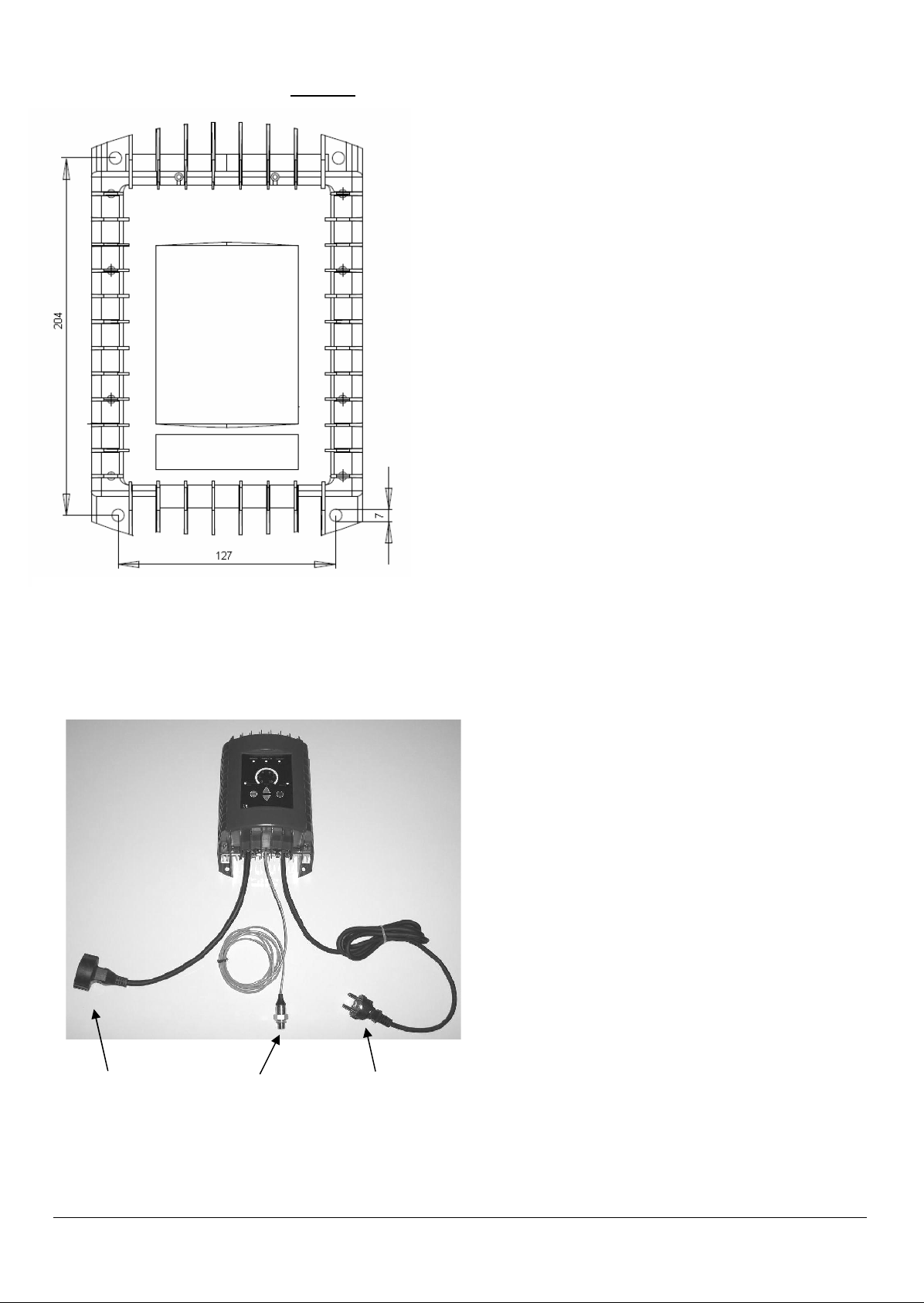
For wall mounting the inverter using the N° 4 holes
7mm diameter arranged in the pattern of holes in
Figure 1.
4.2 Connecting the hydraulic pressure transducer at the pump
Proceed to the hydraulic installing in
accordance with current laws. To control
pressure in feedback you need to connect to
the pump outlet, the pressure transducer
supplied (No. 1 fig 2), ¼ "M, coming from the
central to the inverter.
The type of transducer supplied may be a
different one presented in this handbook, but
maintaining the same connection and
functioning.
Fig. 1: Fixing holes distances (millimetres)
3) 220-230 Vac
Inverter voltage
supply plug
2) Motor pump
voltage supply plug;
Red color for threephase plug
1) Pressure
transducer
Page 5
5
4.2.1 Connecting the pressure transducer to New waterworks system
Connect the pressure transducer in the hole of the filling cap
¼ "F of the pump provided to the output pressure
(depending on the type of pump);
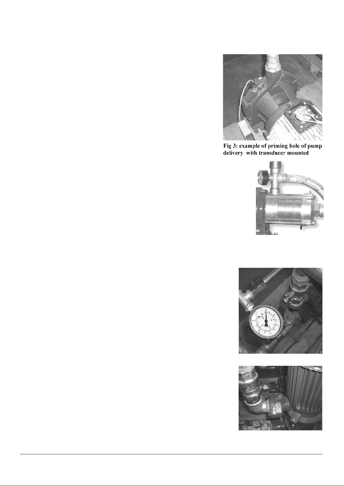
On the delivery of a multistage pump, assembled with a T-fitting is
possible to mount the pressure transducer in place of the pressure
gauge.
Be aware that: in multi-stage pumps with the hole filling near aspiration it
is not possible to mount the pressure transducer at that hole because it
will not do the correct output pressure.
Use ¼” F hole for the pressure gauge, which can be – in case –
removed for connecting the pressure transducer;
Use any other ¼ "F hole on the pump hydraulics connections,
possibly removing the cap (such as a hole for venting air);
Fig. 5: Pressure gauge to replace
Fig. 6: mounting transducer to
venting air hole on the delivery
pump
Fig 4: multistage pump outlet
with manometer to replace
with the transducer
Fig 3: example of priming hole of pump
delivery with transducer mounted
Page 6
6
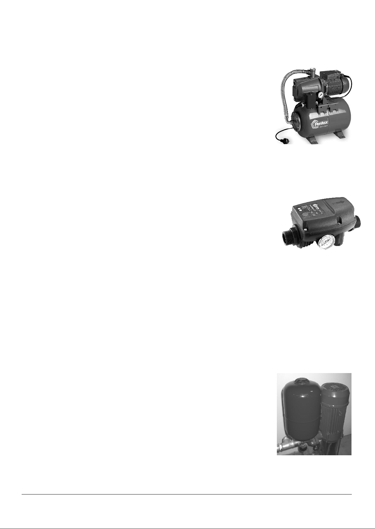
4.2.2 Connecting the pressure transducer to Old waterworks system
Pump comes with PRESSURE-SWITCH with tank or with
galvanized steel tank: mount the pressure transducer in place at
the pressure switch, using reduction to ¼ "M. In case you need to
maintain the switch for maximum pressure additional security,
connect the N.C. output of the switch to ENABLE and 0V contacts
(poles 2 and 5 of J5 electronic board, fig. 10)
Pump comes with flow switch device: replace the flow switch with
a T-fitting flow and in the central hole screwing the pressure
transducer. This allows you to eliminate the problem of any
blocking of the valve flow and to eliminate pressure drop, does
mean eliminate all the problems inherent the flow switch
systems.
It is possible to use a valve or other type of output provided at the delivery of the pump.
In case of installation of the check valve on the outlet of the pump, place the pressure transducer after
the valve.
4.2.3 Membrane Tank
For an optimal pressure control is recommended to mount a small
diaphragm tank (12L are usually good for a pump up to 2Hp).
For a perfect operation of the control of pressure, make sure that the tank is
capable of withstanding the pressure and set the correct pressure to preload before connecting it to (normally 0.5-1 Bar less than the working
pressure) .
Fig. 9: Membrane Tank
Fig 7: pressure switch system
with pressure switch to
replace with transducer
flow switch system
Fig 8: Replace
Page 7
7
4.3 Inverter – Pump connection
Do connect the female schuko cable of the Inverter (No. 2 of fig. 2nd) to the power plug of the pump.
Make sure the pump is in accordance with the operating conditions listed in Chapter 2 of this
handbook. The pump to function with this Inverter must have the appropriate capacitor for the
auxiliary winding and connected to power cable properly dimensioned, with a plug (schuko
recommended).
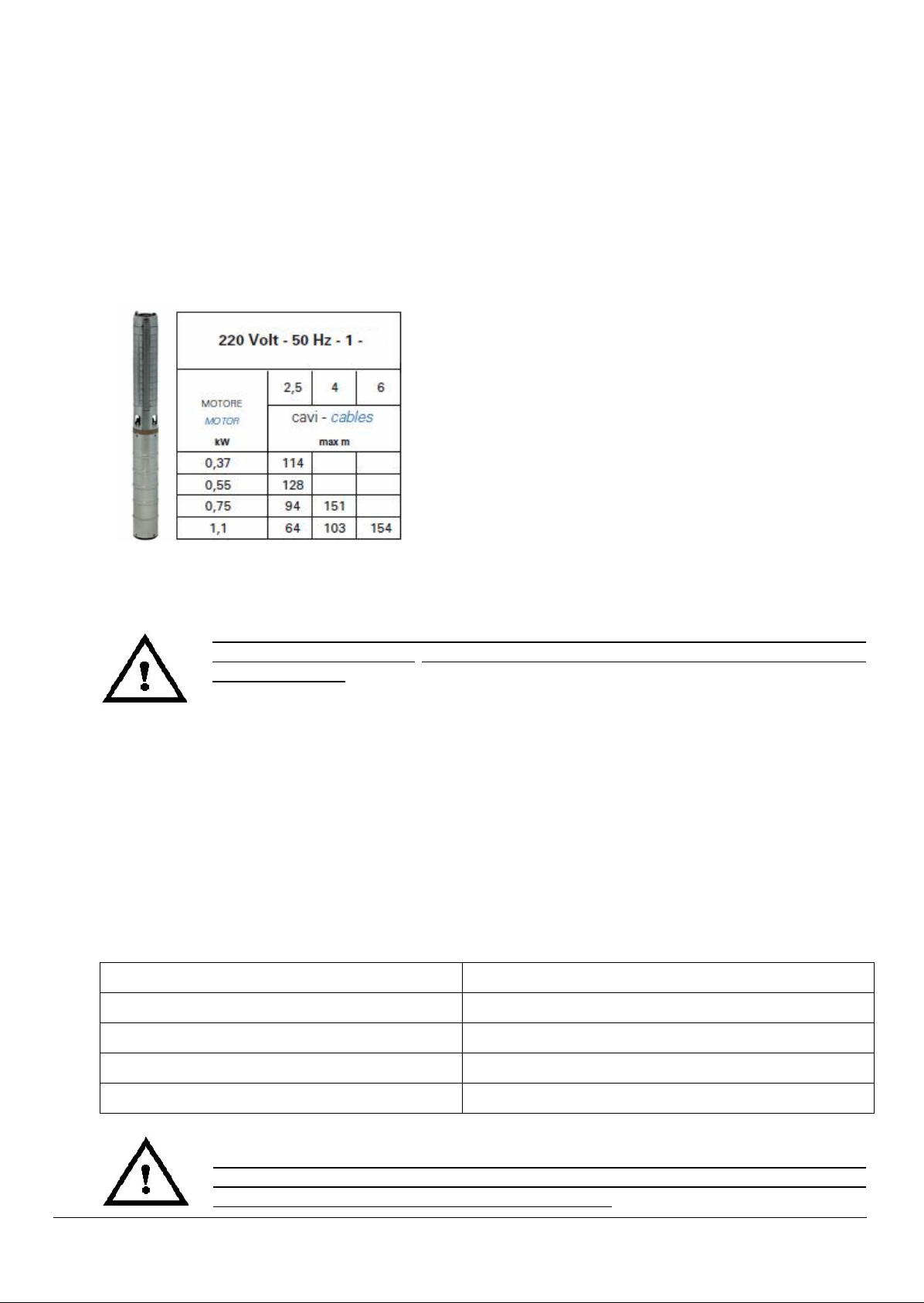
Please do attention to following cable length table if you connect the inverter to a sommersible singlephase motor-pump:
In case of submersed motor pump with a cable
length more than 20 meters be sure that the motorpump is designed to works with inverter (may have
a good phase-phase electrical insulation and not
conductive rolling bearings) otherwise you need to
use the specific output filter (optional – ask our sales
service) connecting it between the inverter output
and the motor pump voltage supply cable.
4.4 Inverter electric connection to line
The line voltage supply must match with the Inverter limits, described on chapter 3 –
WORKING CONDITIONS. Do ensure proper protection from general electrical short
circuit on the line.
The connection to the voltage supply is made by inserting the schuko plug ( No. 3 of Fig. 3) into the
socket power
The plant to which the inverter is connected must be conforms to safety regulations in use:
• Differential automatic switch: IΔn = 30mA
• Magnetic-thermal automatic switch with intervention current proportionate to the power of the
pump installed (see Table 1)
• Ground connection with total resistance less than 100 Ω
• If required by local electrical regulations in force, the installation of a differential circuit breaker,
make sure it is of a type suitable for installation (see table below). The switches are suitable for those
with the characteristic curve for alternating-current fault (type A).
Pump power Kw
Magneto-thermal protection (A)
0.5 (0.75 Hp)
8
0.75 (1 Hp)
12
1.1 (1.5 Hp)
16
1.5 (2 Hp)
25
Table 3: Magneto-Thermal protections
Before reopening of the inverter box to possible change cable or other components,
after functioning, remove voltage and wait at least two minutes, then you can open the
box (danger: contact with electric high voltage parts).
Table 2: cable lengths admitted
Page 8

8
The unit is equipped with all those technical arrangements required to ensure a good functioning
under normal situations installation.
The control system has a entry-filter, also have a current overload protection which guarantees
absolute protection when the Inverter is combined with motors that not exceed the maximum power.
For EMC is good that the power wires of control panel and motor power wires (when the motor are
separated from the inverter) are shielded type (or armoured) with individual conductors of appropriate
section (current density <= 5 A/mm2). These cables must be the minimum length necessary. The
screen conductor must be connected to the ground by both sides. On motor use the metal case for
connection to the ground of the screen.
To avoid loops that can create mass disturbances radiated (antenna effect), the motor operated by
the frequency converter must be connected on the ground individually, always with a low-impedance
using the metallic box of the machine.
The wires from power supply to frequency converter and wires from frequency converter – motor (if
the motor is separated to the Inverter) must be spaced as much as possible, not to create loops, not
make them run parallel less than 50 cm.
Don’t observe these conditions could cancel completely or partially the effect of the filter integrated.
4.5 Access to the electronic board
In case is necessary to change damaged cables, pressure transducer or to add the float switch
contact, you need to open the Inverter case.
The operations of a component for the inverter must be performed only by experienced
personnel qualified by the manufacturer, using only original spare parts supplied by the
manufacturer.
Any action with open box of the Inverter must be made after at least 2 minutes after
open line with appropriate switch or the physical separation from the power supply
cable;
In case of failure to one of the cables or the pressure transducer, for the replacement of that should
be opened by unscrewing the inverter cover the N° 12 screws in the back on the heat sink. For the
extraction of a cable, unscrew the three screws that close the cable triangular plate. Remember to
always replace the O-ring seal on the cable under the plate. To connect the cables in the appropriate
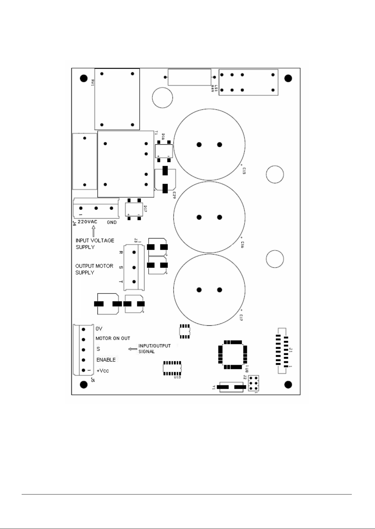
terminals follow the pattern of connections in the electronic board below (fig. 10):
Inverter Power supply cable: contact 220Vac + GND (J4)
Pressure transducer with 4-20 mA output: contact +Vcc, S;
Float switch enable: contact ENABLE, 0V (J5);
Motor ON output signal: Contact MOTOR ON, 0V (J5 - closed when the motor is ON, max. 30V,
3mA)
4.6 Connecting the float contact or other NC contact
To connect an enable Normally Closed contact use the poles 2 (Enable) and 5 (common) of J5 (fig.
10). When the contact open, the Inverter stop the pump; when the contact close, the pump may restart at previous working condition.
For the connection of the float switch contact you need to change the three poles cable of the sensor
with a four poles cable, passing on the same central exit of the transducer cable.
The new connections of pressure transducer and float switch contact must be done
out of the Inverter box, protecting them to humidity, water and dust. Do not practice
others holes to the Inverter case to avoid damages or decrease of the protection and
insulation grade and interruption in anticipation of the guarantee.
Single-phase Motor Power supply cable on FCP109
Three-phase Motor Power supply cable on FCP307: contact R, S,T (J3);
a
nd
FCP111
: contact S, T (J3);
Page 9
9
4.7 Electronic Board connections:
Fig. 10: Electronic Board connections
Page 10

10
5. STARTING AND PROGRAMMING
LED
Description
Power:
Green fixed: Inverter voltage supply is ON
Pump On
Green fixed: Motor ON
Green flashing: Enable OFF condition
Alarm:
Red fixed: Motor stop for a problem that need manual re-start (STOP then START)
Red flashing: Motor stop for a problem with auto re-start
Minimum Flow:
Yellow fixed: Motor stop for minimum output flow
Yellow flashing: Motor is stopping for minimum flow
Dry Working:
Red flashing: Motor stop for dry working condition of the pump, during one of four re-start of
this problem, separated from 15 minuts
Red fixed: final stop after 5th consecutive stop for this problem
Circular Led Bar:
Like a manometer shape of 20 Leds to indicate the instant pressure in BAR. On advanced
regulation to each group of led correspound a function (see table Advanced regulations). In
ALARM condition to each led correspound a different type of alarm (see Alarm table).
Table 5: Led description
Button
Description
Allow to increase the reference pressure; it
allow to go up on the advanced regulation
functions also
Allow to reduce the reference pressure; it
allow to go down on the advanced
regulation functions also
Starting pump; start Self-Regulation Test
on the first installation or after a RESET
Instant Stop of the motor pump
Fig. 11: Control panel
Table 4: Buttons description
Page 11

11
5.1 Programming
A) Make sure the pump is charged (full of water); in case the pump is not charged provide it a
direct voltage supply (without Inverter) until the complete filling of water, then re-connect the
pump to the Inverter;
B) In case the pressure of the system is more than 3 BAR open the delivery to reduce it under this
value, then completely close the delivery or all of the valves on the output of the pump (very
important condition);
C) Press START to start the self-regulation check. Wait roughly one minute for a completed cycle,
and once the flashing Led bar is completed indicate the data saving and the pump stop for null
flow condition (Minimum flow);
D) At this point the Inverter is running; It is now possible to open the delivery of the pump and work;
the reference default pressure, modifiable, is 3 BAR;
E) If necessary, adjust the working pressure acting on keys and on panel; during the
reference pressure setting the led bar is flashing up to one second of data saving; the measured
pressure is indicated by fixed led bar;
F) For a correct over-current motor-pump protecion set the maximum current with F2 on advanced
functions (chap. 5.2) reading the nominal motor data value.
The inverters generally comes to the user with the constructor data (default); if for any reason i.e.
(such as inverters had been previously tested and configured for another pump) the inverter is preregulated, in order to RESET before self-regulation test, is necessary to perform this following:
Command
Procedure
RESET (to restore constructor data)
& press them simultaneously for 5 seconds
Starting SELF-REGOLATION CHECK
After RESET, press
Table 6: Reset and Self-Regulation Check starting
During self-regulation check the velocity and pressure of the pump arrive to maximum
values; if is necessary, limit the maximum pressure before (F7).
We suggest to repeat the self-regulation check after any variation of parameters, in particular for
variation of Maximum Velocity (F4) or Maximum pressure (F7), or in case of variations of the
electrical/mechanical pump conditions, that may appear after long time of working.
5.1.1 Checking the pump stop for delivery closed
At the end of the self-regulation check, done with the delivery of the pump completely closed (all of
the output valves closed) the pump shall be automatically stopping and the Inverter could show the
message "MINIMUM FLOW" by the corresponding Yellow LED. The stop is preceded by a phase of
flashing LED “MINIMUM FLOW”. Verify that the pump stopped and after that the pump re-start
working when opening any valve on pump delivery.
5.1.2 Checking the arrest of the pump dry running
After installing, if is possible, close the water input of the pump and check that, after approximately 40
seconds, the pump stop and show the message “DRY WORKING” with corresponding Red Led.
Page 12

12
5.2 Advanced regulations and control panel visualization
Command
Procedure
Enter on Advanced Regulations
& press them simultaneously for 3 seconds
Press and go up with to enter on the advanced function request, as show on table 7
regulating the value of the selected function on a variation range indicated, on a scale from 0 to 10.
N°
Visualization
Advanced Function
Description
Range
Default
F1
Minimum flow stop
Adjustment of the minimum flow
before pump stop, from the selfregulation value setted.
-10..+10
Step: 1
0
F2
Maximum motor
current
Maximum RMS current setting
– limit value for over-current
thermal protection (A5)
3..9 (11) A for
1..7 A for FCP307
Step: 0.5 A
9 (11)A
7 A
F3
Minimum Motor
Minimum motor velocity
adjustment.
30..70%
Step: 2%
50%
F4
Maximum Motor
Maximum value of the motor
velocity on respect to the
nominal velocity.
90..110%
Step: 1%
105%
(100% for
FCP109)
F5
FCP109 – FCP111:
Starting velocity
FCP307: Rotation
Starting velocity of the motor,
before pressure control
regulation.
Rotation direction on FCP307
40..100%
Step: 3%
0/1
79%
0
F6
Starting maximum
Current
FCP307: Rump
Starting Current – RMS limit
value
Velocity ramp acceleration/deceler.
18..28 A
Step: 0.5 A
1000-10000 RPM/s
Step: 500
26 A
(28 A for
FCP111)
3000 RPM/s
F7
Maximum pressure
Maximum security pressure of
the system.
2..10 Bar
Step: 0.5 Bar
10 Bar
F8
Pressure
Hysteresis
Adjustment of the control
pressure hysteresis.
0.15 ..1 Bar
Step: 0.05 Bar
0.3 Bar
F9
Pressure ramp
Adjustment of the control
pressure ramp on increasingdecreasing.
0.1 .. 2 Bar/s
Step: 0.1 Bar/s
1 Bar/s
F10
Minimum output
value of the
pressure
transducer
Adjustment of the minimum
output value of the pressure
transducer
1..5 mA
Step: 0.2 mA
4 Ma
Velocit
FCP109 and FCP111
y
Veloci
ty
Page 13

13
F11
Maximum output
value of the
pressure
transducer
Adjustment of the maximum
output value of the pressure
transducer
10.. 20 mA
Step: 0.5 mA
20 Ma
F12
Pressure
transducer
measure range
Adjustment of the pressure
transducer range.
10..20 Bar
Step: 0.5 Bar
16 Bar
F13
Proportional P.I.D.
Factor
Proportional factor on the P.I.D.
pressure control
0..6000
Step: 300
3000
F14
Integral P.I.D.
Factor
Integral factor on the P.I.D.
pressure control
0..4000
Step: 200
1000
F15
Minimum flow stop
delay
Delay time on the minimum flow
condition before stopping pump
2..20 sec
Step: 1 sec
10 sec
F16
Dry working stop
delay
Delay time on the dry working
condition before stopping pump
10..100 sec
Step: 5 sec
40 sec
F17
Noiseless working
mode
It is possible change of the
working mode type
0: Normal working
1: Noiseless working
0
F18
Check suspension
It is possible to suspend the self
regulation check using a
theoretical pump curve or to
repeat the check on next START
0: Theoretical curve
1: Start new check
2: Checked curve
1
F19
Phisical quantity
Measures
Measures of different phisical
quantity on respect the
pressure
0: Pressure (0..10)
1: Frequency (15..55)
2: Current (0..10)
3: Voltage (200..240)
4: T [°C] (70..90)
5: Last alarm
6: Motor ΔT[°C](0..100)
0
Table 7: Advanced Functions
WARNING: setting an high Maximum Velocity (function F4) increase the performance
of the pump but can also reduce the endurance of the same for the stress of electrical
and mechanical parts.
NOTES:
Check suspension function (F18-0) eliminate the Self regulation check and regulate the pump working
using a theoretical approximated curve (minimum flow stop is modifiable with F1);
Noiseless working function (F17-1) provide a more silent working power of the motor-pump (low
electromagnetic acoustic noise caused by iron-core vibrations) but increase the power loss and
consequently increases the Inverter temperature;
If the high value of the starting current cause problems on the magneto-thermal switch protection try
reduce this current with F6 and verify that the torque remains sufficient.
Page 14

14
6. PROTECTIONS AND ALARMS
N°
Alarm type with
ALARM led ON
Protection
Description
A1
Current pick
The logic switches off the power instantaneously if this
value exceeds a peak that can damage the power
electronic components. Possible high starting current or
short-circuit on motor.
A2
Over-voltage
The logic switches off the current if the voltage exceeds a
maximum instantaneous limit beyond that can damage
some electronic components of the inverter.
A3
Minimum-voltage
If the voltage goes below the minimum value of 207 Vac
the power supply may provide a under-voltage to some
electronic components; for this the logic switches off the
current.
A4
Over-temperature
IGBT
If the temperature of the power electronic components
(IGBT) exceeds 85°C the inverter provide a thermal
protection and stops the current.
Before this stop protection the Inverter limit the current to
90% of the value imposed (F2)
A5
Motor Over-Current
Thermal protection
To over-current beyond a certain time defined by an I2t
algorithm, the inverter limit the current to protect the
motor from damage to the insulation. For the correct
functioning of this protection regulate the nominal motor
current (F2).
A6
Pressure
transducer problem
In case of a problem or failure of the pressure transducer,
the Inverter switches off the motor current. Re-start must
be manually, pressing STOP followed by START.
A7
Minimum flow
This protection stop the pump when all output are closed
and the flow of water is null. Do not appear “Alarm” led
signalising
A8
Dry working
This protection stop the pump in absence of input flow of
water. After five consecutive re-start, the stop is
permanent and switch on also the “Alarm” led
Table 8: Protections and Alarms
All Alarms are showed with the corresponding Led on the circular Led bar and the red Alarm Led, that
is flashing if the protection have automatic re-start otherwise is fixed if the protection need a manually
re-start doing STOP then START.
Protections and Alarm details:
CURRENT PICK PROTECTION (A1): The Inverter stop immediately the current in case this value
exceed a maximum value limit for the electronic components
CLOSED DELIVERY WORKING PROTECTION (A7): to prevent a closed delivery working, the
control logic read the motor’s working point condition; if this point is under a setting value, the system
switches off the pump, and appears advise “Minimum Flow”. At the end of this condition, the system
restarts its normal operation. The pump curve is detected by the initial self-regulation check.
Page 15

15
DRY WORKING PROTECTION (A8): To avoid that the pump can continue to operate after a problem
in absence of input water, the system read some information of the electric motor, in a time of 30
seconds, and when they go below a minimum, turn off the pump and show the relative signal of alarm
“Dry Working”. The inverter tries N°5 consecutive re-start in this condition, one spaced 15 minutes of
each other. After the fifth consecutive fault, switch on the led Alarm and the re-start must be manually
do, pressing STOP followed by START.
ENABLE OFF: the enable contact (float contact) is open and the led MOTOR ON is flashing.
7. GUARANTEE
Under the current European low: guarantee of 2 years calculated from the date of delivery of
prejudice further provisions of law or contract.
To have service in guarantee, it must submit to the company providing the guarantee certificate
completed.
The guarantee is excluded or interrupted in anticipation if the damage is caused to the following:
External influences, non-professional installation, non-compliance with instructions, interventions by
unauthorized locations, use of not original spare parts and normal wear.
8. DECLARATION OF CONFORMITY
PENTAX SPA - declare that the products :
FCP109
FCP111
FCP307
are conforms to the following European directives and to national law and at following technical
standards:
Machines 98/37/CE
Low Voltage 73/23/CE and subsequent amendments
EMC 89/336/CE
EN60034, EN60335-1, EN 60335-2-41, EN 55014-1, EN 55014-2, EN 61000-3-2,
EN 61000-3-3, EN 61000-3-4, EN 61000-3-12, EN292-1, EN292-2, EN50-178
Manufacturer and depositary of tecnical documentation:
PENTAX S.p.A.
Viale dell’industria, 1
37040 Veronella (VR) - Italia
Gianluigi Pedrollo (President)
Veronella (Vr), 01/01/2008
Page 16

16
 Loading...