

Page 1

OWNER’S GUIDE
ER90/100/200
HOME
VENTILATION
SYSTEMS
J. H. • Rev. 1-93 • Printed in U.S.A. • Form Number 69-0737B—1
Page 2

WELCOME…
…to the world of efficient ventilation. Engineered and
built for long, trouble-free operation, this Honeywell
ER90/100/200 Home Ventilation System provides
proper levels of ventilation with energy savings by
transferring heat and moisture between the exhaust and
fresh air streams. Your home will now be better protected from indoor pollutants such as formaldehyde,
tobacco by-products, radon, moisture, combustion byproducts and carbon monoxide. With the Honeywell
Home Ventilation System you can expect to enjoy the
benefits of a properly ventilated energy efficient home
for years to come.
Features and benefits:
• Recover up to 85 percent of the total heating or
cooling energy in the exhaust air.
• Reduce air conditioning load by up to 0.4 ton during
air conditioning season.
• Operates condensation free. No drain required.
• Easy-to-clean energy transfer wheel assures years
of trouble-free operation.
Page 3

CONTENTS
PAGE
CONTROLS FOR YOUR HOME VENTILATION SYSTEM ................... 2
OPERATING YOUR HOME VENTILATION SYSTEM .......................... 3
GETTING THE MOST FROM YOUR HOME
VENTILATION SYSTEM ................................................................... 4
MAINTENANCE INSTRUCTIONS FOR THE HOME
VENTILATION SYSTEM ................................................................... 6
WARRANTY......................................................................................... 10
BENEFITS OF PERFECT CLIMATE™ AND THE HOME
VENTILATION SYSTEM ................................................................. 11
1 69-0737B—1
Page 4

CONTROLS FOR YOUR HOME VENTILATION SYSTEM
Your Home Ventilation System comes equipped with a factory supplied
control package consisting of:
1. FRESH AIR CONTROL
Fig. 1—Fresh air control for
Home Ventilation System.
Controls the air flow rate in the
system, allowing the homeowner to change the air flow
rate as conditions in the home
INDICATOR
LIGHT
FRESH AIR CONTROL
change. To select the desired
air flow rate position, move the
knob on the controller to the
FRESH AIR
CONTROL
KNOB
MAX
OFF
MIN
desired level. See Fig. 1.
2. DEHUMIDISTAT
Select the desired inside
humidity level for the home.
The dehumidistat will override
the fresh air control and cause
the Home Ventilation System
to operate at high speed until
humidity levels are reduced to
the humidistat setting. At this
point, the dehumidistat will turn
off and airflows will return to
the fresh air control setting. For
summer operation, set
OFF
dehumidistat to
position.
RANGE
SWITCH
M3333
ER90
FRESH AIR CONTROL
HI LO
RANGE
SELECT HI OR LO RANGE - ADJUST AIRFLOW
ER100/200 REMOTE CONTROL
H
I
A
U
T
O
O
L
Fig. 2—Master switch on the
Home Ventilation System cover.
OFF
HI OFF
1
MASTER SWITCH IS ALSO
RANGE SWITCH.
LO
1
ER100/200ER90
ON
M3328
3. MASTER SWITCH
This switch is located on the
unit cover. The switch turns off
the unit completely, disabling
the fresh air control,
dehumidistat and blowers. See
Fig. 2.
2
Page 5

OPERATING YOUR HOME VENTILATION SYSTEM
STEP 1
Set the master
ON
or LO position. The switch light should come on. The system will now
operate whenever the fresh air control or dehumidistat is turned on.
STEP 2
Turn the fresh air control knob to start the unit blowers. The indicator light
should light. The fresh air control varies the speed of the blower. This
allows you options for the amount of ventilation. The Home Ventilation
System is a balanced system; the amount of fresh air introduced into the
house is always balanced with the amount of air exhausted from the
house. Increase the ventilation rate if you feel the house is stuffy, or if
there is an above average occupancy rate. In most applications, a
midrange setting on the fresh air control will provide proper ventilation. On
some units, you may also select a
ventilation.
STEP 3
When using a dehumidistat, set the dehumidistat to the desired humidity
level. If your heating system has a powered humidifier, be sure the
dehumidistat is set at least ten percent relative humidity above your
humidistat. It may be necessary to lower the humidistat setting to avoid
condensation in the winter. This ensures a proper humidity level in the
home. Set dehumidistat to
STEP 4
Your system is now fully functional. Perform an occasional check to
ensure that the exhaust and intake outlets for the unit are clear. You
should check that intake outlets are not close to any source of contamination such as barbecues or automobile exhaust. If you find a source of
contamination close, move it. Be sure to check that the exhaust air is not
being directed to the intake air hood.
ON/OFF
switch located on the Home Ventilation System to
HI
or
LO
range when adjusting
OFF
position for summer operation.
3 69-0737B—1
Page 6

GETTING THE MOST FROM YOUR HOME VENTILATION SYSTEM
FRESH AIR CONTROL
The low voltage remote fresh air controls (ER100/200 only) allow convenient operation of the ventilation system from the living area of your home.
The control performs the following four functions:
1. A two-position
LO
or HI speed range. Only certain models have this feature.
2. The control knob allows selection of continuous ventilation rates
within the pre-selected
3. This same knob is used to place the ventilator into the
In
AUTO,
override switches that can be installed as options with your Home
Ventilation System.
4. An indicator light above the
unit.
MOISTURE CONTROL
Continual operation of the ventilation is recommended for optimum
reduction of indoor air pollution and control of humidity. Increased
moisture removal will always occur at maximum ventilation rates. This
setting should be used when first occupying a newly built home to
remove excess moisture from new wood, plaster, cement and other
moisture absorbing construction materials. If your system is wired
to a dehumidistat, preselected moisture levels can be maintained
automatically. Severe moisture conditions can be controlled with the
sensible energy transfer wheel when the indoor air contains more
moisture than the outdoor air.
HI-LO
range switch lets you place the ventilator into
HI
or LO speed range.
AUTO
the blower is operated by the dehumidistat and/or
HI-LO
switch verifies operation of the
mode.
REMOTE OVERRIDE SWITCH FUNCTIONS
Your ventilation system may incorporate one or more remotely located
switches to activate bathroom ventilation, a dehumidistat, or any combination of these or other ventilation functions. A remote switch in the
position will cause the ventilator to operate at high speed until the override
switch is turned off. The ventilator will automatically return to its previous
setting on the fresh air control. The remote override switch, in combination
with the
exhaust when continuous ventilation is not required. Continuous operation
is recommended except when the home is unoccupied, or when proper
ventilation is provided by other means like open doors and windows.
AUTO
mode, is especially useful for intermittent bathroom
4
ON
Page 7

FROST CONTROL
Some Home Ventilation System models have built-in automatic preheat
frost control systems that allow the unit to operate in cold weather regions.
Areas where the winter design temperature does not fall below 5° F [-15°
C] will not require a preheater. The function of the frost control is to ensure
that the intake air brought into the Home Ventilation System is not below
10° F [-12° C]. This ensures proper operation of the Home Ventilation
System. Operation is indicated by the indicator light located on the Home
Ventilation System cabinet next to the
indicator light is on when the outdoor temperature is below 10° F [-12° C]
or the
TEST
button is pressed. The preheat system is functioning if the
indicator light comes on when the
preheat system before the heating seasons starts each year. Follow the
instructions on the cabinet for testing.
PRESS-TO-TEST
TEST
button is pressed. Test the
button. The
IMPORTANT:
Release the TEST button as soon as the neon light comes
on. Pressing the TEST button longer can cause overheating of the
Home Ventilation System.
5 69-0737B—1
Page 8

MAINTENANCE INSTRUCTIONS FOR THE HOME
VENTILATION SYSTEM
CAUTION
!
Electric shock hazard.
Can cause personal injury or equipment damage.
Disconnect power supply before doing maintenance.
The Home Ventilation System must be maintained on a regular basis for
the best efficiency. Honeywell recommends the Home Ventilation System
to be cleaned and checked at least twice a year, preferably at the start of
each heating and cooling season.
CAUTION
!
Make sure the master switch is in
OFF
position before doing any
maintenance.
Check and/or clean as follows:
Room Air Filter: Remove and wash this wire mesh filter to assure
proper airflow in the unit. See Fig. 3. Only the ER90/100s have the
room air filter.
Fig. 3—ER90/100 stale air intake filter and fresh air filter location.
THUMBSCREWS
COVER
STALE AIR
INTAKE FILTER
FRESH
AIR
INTAKE
FILTER
THUMBSCREWS
M3324
6
Page 9
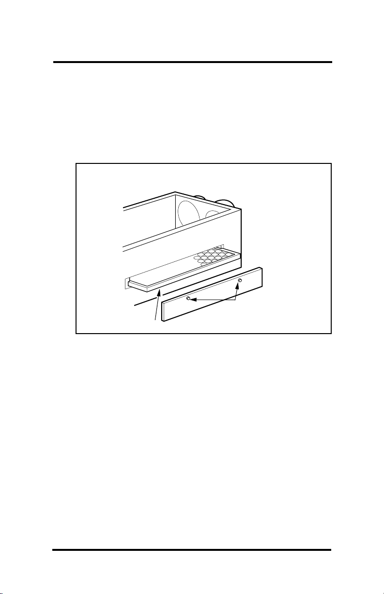
Fresh Air Filter: Replace the fresh air filter at least twice a year. To
remove filter:
1. Unscrew access panel thumbscrews to remove the filter access
panel. See Figs. 3 and 4.
2. Slide the fresh air filter out of the Home Ventilation System.
3. Check filter and replace if clogged.
4. Place the filter access panel back on the Home Ventilation
System and tighten the thumbscrews.
Fig. 4—ER200 fresh air filter location.
THUMB-
FRESH
AIR FILTER
SCREWS
M3323
Weather Caps: Check to ensure that the outside fresh air inlet and
exhaust weather caps do not become clogged with debris like
grass, leaves and snow.
Energy Transfer Wheel: Check the energy transfer wheel for build-up
of dirt and debris.
NOTE: Energy transfer is not affected by stained surfaces.
To remove and clean the ER90/100s Energy Transfer Wheel:
1. Unscrew the screws holding the Home Ventilation System cover
and remove the cover. See Fig. 5.
2. Take out the center divider.
3. Loosen the screw in the center of the wheel hub cap.
4. Rotate hub cap counterclockwise and remove.
5. Grasp hub with two fingers and take straight off the drive shaft.
IMPORTANT:
Lift only by the hub.
7 69-0737B—1
Page 10
5. Spray the energy transfer wheel thoroughly with household spray
cleaner (Fantastic™ or equivalent). Rinse with warm water. Use
a soft brush to remove stains between the plastic windings.
Shake excess water from the wheel.
6. Replace the wheel on the drive shaft.
NOTE: Rotate the wheel counterclockwise until the pin in the shaft has
engaged in the slot in the bottom of the hub. The end of the drive
shaft and the face of the hub will be flush.
7. Put hub cap on, rotate
Fig. 5—ER90/100 Energy Transfer Wheel and belts location.
ENERGY
TRANSFER
WHEEL
ENERGY TRANSFER
WHEEL HUB CAP
in clockwise direction,
tighten screw.
8. Install the center divider.
9. Replace the Home
Ventilation System
cover and tighten the
screws.
BLOWER
AND
MOTOR
DRIVE BELT SET
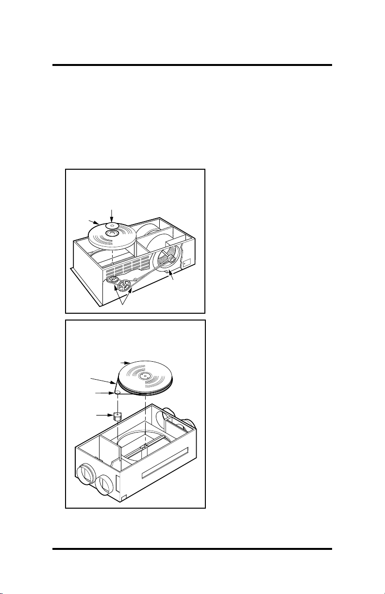
Fig. 6—ER200 Energy Transfer
Wheel and belts location.
ENERGY
TRANSFER WHEEL
WHEEL DRIVE
BELT
WHEEL DRIVE
PULLEY
WHEEL DRIVE
MOTOR
M3325
M3322A
To remove and clean the
ER200 Energy Transfer
Wheel:
1. Unscrew the screws
holding the ventilator
door and open the door.
2. Take out the center
divider.
3. Remove the belt from
the rim of the wheel.
See Fig. 6.
4. Unscrew the screw in
the center of the hub.
5. Use the rim of the wheel
and lift the wheel
straight off the drive
shaft.
6. Spray the energy
transfer wheel thoroughly with household
spray cleaner (Fantastic™ or equivalent).
Rinse with warm water.
Use a soft brush to
remove stains between
8
Page 11

the plastic windings. Shake excess water from the wheel.
7. Replace the wheel on the drive shaft.
8. Replace and tighten the screw in the center of the hub.
9. Replace the belt on the wheel.
10. Reinstall the center divider.
11. Close the ventilator door and tighten the screws.
Belt Drives: If the blower is operating (air coming out of fresh air vent)
but energy transfer wheel does not rotate, check the pulley system.
NOTE: ER90/100 will require removing the energy transfer wheel to check
the pulley system.
See Figs. 5 and 6. Replace broken or stretched belts.
ON, HI
If the blower fails to operate with the master switch in the
LO
position and the Fresh Air Control on, check circuit breakers in
house electrical panel. If power is supplied to unit but blower does not
operate, contact your local HVAC contractor.
or
9 69-0737B—1
Page 12

LIMITED WARRANTY
Honeywell warrants this product to be free from defects in the workmanship or materials, under normal use and service, for a period of one (1)
years from the date or purchase by the consumer. If, at any time during
the warranty period, the product is defective or malfunctions, Honeywell
shall repair or replace it (at Honeywell’s option) within a reasonable period
of time.
If the product is defective, please contact:
a) the dealer from whom you purchased it, or
b) the local Honeywell Residential Sales Office who will assist you in
locating a qualified service representative,
c) the Honeywell Customer Assistance Center at 1-800-468-1502.
This warranty does not cover removal or reinstallation costs. This
warranty shall not apply if it is shown by Honeywell that the defect or
malfunction was caused by damage which occurred while the product
was in the possession of a consumer.
Honeywell’s sole responsibility shall be repair or replace the product
within the terms stated above. HONEYWELL SHALL NOT BE LIABLE
FOR ANY LOSS OR DAMAGE OF ANY KIND, INCLUDING ANY
INCIDENTAL OR CONSEQUENTIAL DAMAGES RESULTING, DIRECTLY OR INDIRECTLY, FROM ANY BREACH OF ANY WARRANTY,
EXPRESSED OR IMPLIED, OR ANY OTHER FAILURE OF THIS
PRODUCT. Some states do not allow the exclusion or limitation of
incidental or consequential damages, so this limitation may not apply to
you.
THE WARRANTIES SET FORTH HEREIN ARE EXCLUSIVE, AND
HONEYWELL EXPRESSLY DISCLAIMS ALL OTHER WARRANTIES,
WHETHER WRITTEN, ORAL, IMPLIED OR STATUTORY, INCLUDING
BUT NOT LIMITED TO ANY WARRANTIES OF MERCHANTABILITY,
WORKMANSHIP, OR FITNESS FOR A PARTICULAR PURPOSE.
This warranty gives you specific legal rights, and you may have other
rights which vary from state to state.
If you have any questions concerning this warranty, please write
our Customer Assistance Center, Honeywell Inc., P.O. Box 524, MN272164, Minneapolis, Minnesota 55440-0524 or call toll-free at
1-800-468-1502, Monday-Friday, 7:00 am.-5:30 p.m. Central time.
In Canada, Honeywell Limited/ Honeywell Limitee, 740 Ellesmere Road,
Scarborough, Ontario M1P 2V9.
10
Page 13

THE BENEFITS OF PERFECT CLIMATE™ AND THE HOME
VENTILATION SYSTEM
We take it for granted that our homes protect us from the elements.
But, because of tighter, better quality home constructions, our indoor
environments may be exposing us to unacceptable levels of the very
things we are trying to escape—excessive heat, dryness, humidity,
toxic gases, dust and contaminants—sealed neatly in by the
weatherproofing.
So, what’s the weather forecast for indoors?
Today’s indoor forecast is stormy weather for many homeowners. But
rapid clearing and fresh breezes are just around the corner!
FEELING RIGHT AT HOME
Unlike what the outdoor brings us, you can have control of indoor conditions. Temperature, humidity levels and air quality all can affect physical
health, mental attitude, general comfort and energy savings. With today’s
technological advances, you can achieve a “perfect climate” indoors.
After all, people look to their homes as a place to escape the stresses
of work, a busy lifestyle and an increasingly polluted outdoor environment.
Creating a perfect indoor climate is becoming critical to feeling right at
home.
The Honeywell Home Ventilation System removes stale, unhealthy air and
replaces it with a stream of fresh air. The difference a Honeywell Home
Ventilation System makes is that it transfers moisture as well
as heat.
The Honeywell system uses an exclusive design, a rotating wheel
constructed of many layers of a fine polymer material that work to recover
up to 80 percent of the total heating or cooling energy in the exhaust air.
Have you considered the complete package of perfect climate controls for
your home?
CONSIDER THE COMPLETE PACKAGE FOR PERFECT CLIMATE™
11 69-0737B—1
Page 14

FOR YOUR HOME
1. Honeywell Chronotherm III™ Programmable Thermostats
How it works...
OPTIMAL
EFFICIENCY AIR
CONDITIONER
OR HEAT PUMP
M3340A
THE
HOME
VENTILATION SYSTEM
IS ONE PART OF A PERFECT
TM
CLIMATE, AN INDOOR ENVIRONMENT
THAT MAKES YOU FEEL BETTER, ALLOWS YOU
TO LIVE AND WORK MORE COMFORTABLY, MAINTAINS
PRECISE INDOOR TEMPERATURE, HUMIDITY AND AIR
QUALITY, AND ACHIEVES MAXIMUM ENERGY SAVINGS.
HONEYWELL
DEHUMIDISTAT
CONDITIONED
AIR
HUMIDIFIER
HONEYWELL
WATER FILTER
HOME
VENTILATION
SYSTEM
FRESH AIR
CONTROL
OPTIMAL
EFFICIENCY
FORCED AIR
FURNACE
HONEYWELL
CHRONOTHERM
PROGRAMMABLE
THERMOSTAT
HONEYWELL
TM
ELECTRONIC
AIR CLEANER
PERFORMANCE
STATUS
INDICATOR
AIR
COLD AIR
RETURN
RETURN AIR
CONDITIONED
HONEYWELL
ELECTRONIC AIR CLEANER
REGISTER
FRESH
AIR TO
HOME
HONEYWELL
RESIDENTIAL
SECURITY
SYSTEMS
HONEYWELL
HOME
VENTILATION
SYSTEM
SUPPLY AIR
REGISTER
STALE
AIR FROM
BATHS
STALE AIR
EXHAUST
FRESH AIR
INTAKE
TM
2. Honeywell F50, the air cleaners of choice
3. Honeywell Dehumidistats
4. Honeywell Home Ventilation Systems
5. F76 Water Filter
6. Honeywell Home Security Systems
PERFECT CLIMATE™
12
Page 15

DESCRIBING PERFECTION
The most convenient, most energy efficient, cleanest, healthiest and
most comfortable indoor environment possible today! Perfect climate is
achieved when the five core components of a home’s climate system
work together:
• optimal efficiency heating and cooling equipment.
• precise, programmable temperature control.
• effective indoor air quality control.
• controlled humidity.
• proper ventilation and air distribution.
PRODUCTS FOR A
Heating and cooling system: This is the workhorse of your indoor
climate system. Good advice is to have your local heating/cooling
contractor tune up your system annually for comfort, safety and
economy reasons. If your heating plant is old, think about replacing
it with a modern and improved unit. Advances in product technology
have very impressively increased the efficiency of equipment.
Sometimes the improved performance will pay back much of the
cost in a few short years.
PERFECT CLIMATE™
13 69-0737B—1
Page 16

Home and Building Control Home and Building Control Helping You Control Your World
Honeywell Inc. Honeywell Limitée
1985 Douglas Drive North 740 Ellesmere Road
Golden Valley, Minnesota 55422 Scarborough, Ontario
M1P 2V9
QUALITY IS KEY
Page 17

GUIDE DE L’UTILISATEUR
ER90/100/200
SYSTÈMES DE
VENTILATION
RÉSIDENTIELS
J. H. • Rev. 1-93 • Imprimé aux États-Unis • Form Number 69-0737B—1
Page 18

BIENVENUE…
…dans l’univers des systèmes de ventilation efficaces.
Résistants, fiables et durables, les systèmes de
ventilation résidentiels ER90/100/200 de Honeywell
assurent une ventilation efficace et permettent
d’économiser l’énergie grâce au transfert de chaleur et
d’humidité entre le courant d’air frais et le courant d’air
évacué. Votre maison sera protégée mieux que jamais
contre les polluants intérieurs comme le formaldéhyde,
les sous-produits du tabac, le radon, l’humidité, les
sous-produits de combustion et le monoxyde de
carbone. Vous bénéficieriez des avantages d’une
maison bien ventilée et à haut rendement énergétique
des années durant.
Caractéristiques et avantages:
• Récupération, jusqu’à 85 pour cent, de l’énergie
requise pour réchauffer ou refroidir l’air évacué.
• Diminution de 0,4 tonne de la charge des
installations de conditionnement d’air pendant la
période de climatisation.
• Aucune condensation. Ne nécessite pas de drain.
• Roue de transfert d’énergie fiable et facile à nettoyer.
Page 19

TABLE DES MATIÈRES
PAGE
RÉGULATEURS DU SYSTÈME
DE VENTILATION RÉSIDENTIEL ........................................................ 2
FONCTIONNEMENT DU SYSTÈME
DE VENTILATION RÉSIDENTIEL ........................................................ 3
UTILISATION EFFICACE DU SYSTÈME
DE VENTILATION RÉSIDENTIEL ........................................................ 4
INSTRUCTIONS RELATIVES À LA MAINTENANCE
DU SYSTÈME ....................................................................................... 6
GARANTIE........................................................................................... 10
LES AVANTAGES DE L’AMBIANCE PARFAITE (PERFECT
CLIMATE
MD
) ET DU SYSTÈME DE VENTILATION RÉSIDENTIEL .. 11
1 69-0737B—1
Page 20

RÉGULATEURS DU SYSTÈME DE VENTILATION RÉSIDENTIEL
Le système de ventilation résidentiel est muni des régulateurs suivants,
installés en usine:
1. UN RÉGULATEUR D’AIR FRAIS
Fig. 1—Régulateur d’air frais—
système de ventilation
résidentiel.
Ce régulateur règle le débit
d’air dans le système. Il permet
de modifier le débit lorsque les
conditions intérieures
VOYANT
BOUTON DU
RÉGULATEUR
D'AIR FRAIS
FRESH AIR CONTROL
MAX
OFF
MIN
changent. Pour choisir le débit
d’air souhaité, positionner le
bouton du régulateur à la
vitesse voulue. Voir la fig. 1.
2. UN DÉSHUMIDISTAT
Ce régulateur permet de
choisir le taux d’humidité à
l’intérieur de la maison. Le
déshumidistat prend priorité
sur le régulateur d’air frais et
fait fonctionner le système à
vitesse élevée jusqu’à ce que
le taux d’humidité soit ramené
au point de consigne. Le
déshumidistat cesse alors de
fonctionner et le débit d’air est
de nouveau réglé par le
SÉLECTEUR
DE
VITESSE
MF3333
ER90
FRESH AIR CONTROL
HI LO
RANGE
SELECT HI OR LO RANGE - ADJUST AIRFLOW
RÉGULATEUR À DISTANCE MODÈLES ER100/200
H
I
A
U
T
O
O
L
régulateur d’air frais. L’été,
régler le déshumidistat à OFF.
Fig. 2—Interrupteur principal
sur le couvercle du système de
ventilation résidentiel.
OFF
HI OFF LO
1
ER100/200ER90
1
L'interrupteur principal est aussi
un sélecteur de vitesse.
ON
MF3328
3. UN INTERRUPTEUR
PRINCIPAL
Cet interrupteur est situé sur le
couvercle de l’appareil. Il
permet de fermer
complètement l’appareil,
mettant hors service le
régulateur d’air frais, le
déshumidistat et les
ventilateurs. Voir la fig. 2.
2
Page 21

FONCTIONNEMENT DU SYSTÈME DE VENTILATION RÉSIDENTIEL
ÉTAPE 1
Mettre l’interrupteur principal ON/OFF sur le boîtier du ventilateur à ON
ou LO. Normalement, le voyant de l’interrupteur s’allume. Le système
fonctionnera lorsque le régulateur d’air frais ou le déshumidistat sera en
marche.
ÉTAPE 2
Tourner le bouton du régulateur d’air frais pour faire fonctionner le
ventilateur de l’appareil. Normalement, le voyant s’allume. Le régulateur
d’air frais fait varier la vitesse du ventilateur; il permet de choisir le niveau
de ventilation. Le système de ventilation résidentiel est un système à
équilibrage d’air : la quantité d’air frais est toujours égale à la quantité d’air
évacué. Si la maison n’est pas bien ventilée ou si le nombre d’occupants
est plus élevé qu’à l’habitude, augmenter la ventilation. Généralement, un
débit d’air moyen assure une ventilation adéquate. Certains modèles
comportent un sélecteur de vitesse qui permet de régler la ventilation à HI
ou à LO.
ÉTAPE 3
Régler l’humidistat au taux d’humidité désiré. Si le système de chauffage
est muni d’un humidificateur, s’assurer que le déshumidistat est réglé à un
taux d’humidité relative d’au moins dix pour cent supérieur à celui de
l’humidistat. L’hiver, il peut être nécessaire d’abaisser la valeur de
consigne de l’humidistat pour empêcher la condensation et maintenir ainsi
un niveau d’humidité adéquat dans la maison. L’été, régler le
déshumidistat à OFF.
ÉTAPE 4
Le système est maintenant prêt à fonctionner. Voir de temps à autre si les
orifices de prise d’air frais et d’extraction de l’air vicié sont obstruées.
Veiller à ce qu’aucune source de pollution (p. ex. barbecue ou tuyau
d’échappement de voiture) ne se trouve à proximité de la prise d’air frais.
Le cas échéant, éloigner ces sources de pollution. L’air évacué ne doit
pas souffler en direction de la prise d’air.
3 69-0737B—1
Page 22

UTILISATION EFFICACE DU SYSTÈME DE VENTILATION RÉSIDENTIEL
RÉGULATEUR D’AIR FRAIS
Le régulateur d’air frais à distance basse tension (ER100/200 seulement)
permet de faire fonctionner le système de ventilation à partir d’un endroit
commode dans la maison. Il comporte quatre fonctions:
1. Un sélecteur de vitesse à deux positions, HI et LO, qui permet de
faire fonctionner le ventilateur à vitesse élevée ou à basse vitesse.
Cette caractéristique n’existe que sur certains modèles.
2. Le bouton du régulateur permet de choisir une ventilation continue à
l’intérieur de la gamme de vitesses présélectionnée.
3. Le bouton du régulateur permet également de faire fonctionner
le ventilateur en mode AUTO. Le ventilateur est alors commandé
par le déshumidistat et (ou) les régulateurs de dérogation installés
en option.
4. Un voyant, au-dessus de l’interrupteur HI-LO, permet de vérifier si
l’appareil fonctionne.
RÉGULATION DE L’HUMIDITÉ
Pour réduire la pollution de l’air intérieur et assurer une régulation de
l’humidité, faire fonctionner le ventilateur de façon continue. Pour abaisser
davantage le taux d’humidité, augmenter la ventilation. Ce type de réglage
est recommandé pour une maison neuve, car il permet d’éliminer l’excès
d’humidité provenant des matériaux neufs (bois, plâtre, béton) et d’autres
matériaux à haute teneur en humidité. Si l’appareil est relié à un
déshumidistat, le taux d’humidité sera maintenu automatiquement aux
niveaux préréglés. Pour résoudre un grave problème d’humidité, utiliser la
roue de transfert d’énergie sensible.
RÉGULATEURS DE DÉROGATION À DISTANCE
Le système de ventilation peut comprendre un ou plusieurs régulateurs à
distance permettant d’assurer une bonne ventilation dans la salle de
bains, un déshumidistat, ou d’autre types de régulateurs. Lorsqu’un
régulateur à distance est à ON, le ventilateur fonctionne à vitesse élevée
jusqu’à ce qu’il soit mis à OFF. Le ventilateur est alors commandé de
nouveau par le régulateur d’air frais. Le fonctionnement avec régulation à
distance et en mode AUTO permet d’assurer un ventilation intermittente
adéquate dans la salle de bains lorsqu’une ventilation continue n’est pas
nécessaire. Le fonctionnement du ventilateur en continu est recommandé
sauf si la maison est inoccupée ou que d’autres moyens efficaces sont
utilisés (p. ex. portes et fenêtres ouvertes).
4
Page 23

PROTECTION CONTRE LE GEL
Certains ventilateurs sont munis d’un dispositif intégré et automatique de
préchauffage qui permet au système de fonctionner dans les régions
plus froides. Ce dispositif maintient l’air frais au-dessus -12 °C (10 °F) et
assure un meilleur fonctionnement du ventilateur. Il n’est pas nécessaire
dans les régions où la température ne descend pas au-dessous de -15
°C (5 °F). Le voyant sur le boîtier du ventilateur, près du bouton d’essai,
s’allume lorsque le ventilateur est en marche. Lorsque la température
extérieure est au-dessous de -12 °C (10 °F) ou que le bouton d’essai est
enfoncé, le voyant s’allume. Le dispositif de préchauffage fonctionne
lorsque le bouton est enfoncé et que le voyant s’allume. Vérifier le
dispositif de préchauffage chaque année, avant le début de la période
de chauffage. Suivre les instructions sur le boîtier.
IMPORTANT:
Relâcher le bouton d’essai dès que le voyant s’allume. Ne
pas appuyer longtemps sur le bouton d’essai, car le système
pourrait surchauffer.
5 69-0737B—1
Page 24

INSTRUCTIONS RELATIVES À LA MAINTENANCE DU SYSTÈME
AVERTISSEMENT
!
Risque de chocs électriques
Peut causer des blessures ou endommager le matériel
Couper l’alimentation électrique avant de procéder à la
maintenance du système.
Pour que le système de ventilation résidentiel fonctionne efficacement, en
assurer la maintenance à intervalles réguliers. Le nettoyer et le vérifier au
moins deux fois par année, de préférence au début de la période de
chauffage ou de climatisation.
AVERTISSEMENT
!
S’assurer que l’interrupteur est à OFF avant de procéder à la
maintenance du système.
Marche à suivre pour la maintenance et le nettoyage:
Filtre de prise d’air vicié: Enlever le filtre et le laver pour maintenir un
débit d’air adéquat dans l’appareil. Voir la fig. 3. Seuls les modèles
ER90 et ER100 sont munis d’un filtre de prise d’air vicié.
Fig. 3—Emplacement du filtre d’air vicié et du filtre d’air frais modèles ER90/100
VIS À
AILETTES
COUVERCLE
FILTRE
DE PRISE
D'AIR
FRAIS
VIS À
AILETTES
FILTRE
DE PRISE
D'AIR VICIÉ
MF3324
6
Page 25

Filtre d’air frais: Remplacer le filtre d’air frais au moins deux fois par
année. Pour enlever le filtre:
1. Enlever le panneau d’accès au filtre en dévissant les vis à
ailettes. Voir les fig. 3 et 4.
2. Glisser le filtre pour le retirer.
3. Vérifier le filtre et le remplacer s’il est obstrué.
4. Remettre le panneau d’accès et serrer les vis.
Fig. 4—Emplacement du filtre d’air frais - modèle ER200
VIS À
FILTRE
D'AIR FRAIS
AILETTES
MF3323
Couvercles anti-intempérie: Vérifier si des débris (herbe, feuilles,
neige) obstruent les grilles.
Roue de transfert d’énergie: Vérifier si la roue de transfert d’énergie
est sale ou obstruée.
Remarque: Les taches ne nuisent pas au transfert d’énergie.
Marche à suivre pour enlever et nettoyer la roue de transfert d’énergie sur
les modèles ER90/100:
1. Dévisser le couvercle du ventilateur et l’enlever.
2. Retirer la cloison centrale .
3. Tourner le chapeau du moyeu dans le sens antihoraire
et l’enlever.
4. Saisir le moyeu avec les doigts et le retirer de l’arbre
d’entraînement.
IMPORTANT:
Soulever la roue par le moyeu uniquement
.
7 69-0737B—1
Page 26

5. Vaporiser un produit de nettoyage domestique (p. ex. du
Fantastic
MD
ou un produit semblable) sur la roue de transfert
d’énergie. Rincer à l’eau tiède. Enlever les taches entre les
enroulements en plastique avec une brosse douce. Secouer pour
enlever l’excès d’eau.
6. Reposer la roue sur l’arbre d’entraînement.
REMARQUE: Tourner la roue dans le sens antihoraire jusqu’à ce que la
tige sur l’arbre soit entrée dans la fente au bas du moyeu. L’extrémité
de l’arbre d’entraînement et la face du moyeu sont alors alignées.
7. Replacer le chapeau du
moyeu et le tourner
Fig. 5—Emplacement de la
roue de transfert d’énergie et
des courroies - modèles ER90
et ER100.
ROUE DE
TRANSFERT
D'ÉNERGIE
CHAPEAU DU
MOYEU DE LA ROUE DE
TRANSFERT D'ÉNERGIE
dans le sens horaire.
8. Replacer la cloison
centrale.
9. Replacer le couvercle et
serrer les vis.
Marche a suivre pour enlever
et nettoyer la roue de transfert
d’energie sur le modele
ER200:
1. Dévisser les vis de la
porte du ventilateur et
enlever la porte.
2. Retirer la cloison
MF3325
VENTILATEUR
ET MOTEUR
COURROIES
D'ENTRAÎNEMENT
centrale.
3. Enlever la courroie de la
jante de la roue.
4. Dévisser la vis au centre du moyeu.
5. À l’aide de la jante, soulever la roue de son arbre d’entraînement.
6. Vaporiser un produit de nettoyage domestique (p. ex. du Fantastic
ou un produit semblable) sur la roue de transfert d’énergie. Rincer
à l’eau tiède. Enlever les taches entre les enroulements en
plastique avec une brosse douce. Secouer
pour enlever l’excès d’eau.
7. Reposer le moyeu sur l’arbre d’entraînement.
8
Page 27

REMARQUE: Tourner la roue dans le sens antihoraire jusqu’à ce
que la tige de l’arbre soit bien entrée dans la fente au bas du
moyeu. L’extrémité de l’arbre d’entraînement et la face du moyeu
sont alors alignées.
8. Replacer et serrer la vis au centre du moyeu.
9. Replacer la courroie sur la roue.
10. Replacer la cloison centrale.
11. Fermer la porte du ventilateur et serrer les vis.
Entraînement de la courroie: Si le ventilateur est en marche (de l’air sort
par les évents d’air frais) mais que la roue de transfert d’énergie ne
tourne pas, vérifier le système de poulies.
REMARQUE: Sur les modèles ER90/100, il faut enlever la roue de
transfert d’énergie pour vérifier le système de poulies.
Voir les fig. 5 et 6.
Fig. 6—Emplacement de la
roue de transfert d’énergie et
des courroies - modèle ER200
Roue de
transfert d'énergie
Courroie entraînement
de la roue
Courroie entraînement
du moteur
Moteur entraînement
de la roue
Remplacer les courroies
brisées ou lâches.
Si le ventilateur ne
fonctionne pas lorsque
l’interrupteur principal est à
ON, HI ou LO et que le
régulateur d’air frais est en
marche, vérifier les
disjoncteurs dans la boîte
électrique de la maison. Si
le courant se rend à
l’appareil mais que le
ventilateur ne fonctionne
pas, consulter un spécialiste
en conditionnement d’air.
MF3322A
9 69-0737B—1
Page 28

GARANTIE RESTREINTE DE HONEYWELL
Honeywell garantit que le présent produit est exempt de tout vice de
fabrication ou de matière dans la mesure où il en est fait une utilisation et
un entretien convenables et ce, pour une période de un an à partir de la
date d’achat par un consommateur. Si le produit est défectueux ou s’il
fonctionne mal pendant la période de garantie, Honeywell le réparera ou
(selon son gré) le remplacera dans un délai raisonnable.
Si votre produit est défectueux, veuillez communiquer avec:
a) le fournisseur qui vous a vendu le produit, ou
b) le bureau des ventes du groupe de la Régulation résidentielle et
commerciale de Honeywell de votre région qui vous donnera le nom
d’un technicien qualifié,
c) le Honeywell Customer Services Dept. au 1-800-468-1502.
La présente garantie ne couvre pas les frais de main-d’oeuvre pour le
retrait ou la réinstallation de l’appareil. Cette garantie n’est pas valide si
Honeywell peut démontrer que la défectuosité ou le mauvais
fonctionnement est attribuable à une utilisation ou à une manipulation
inadéquate du produit lorsqu’il était entre les mains du client.
La responsabilité de Honeywell se limite à réparer ou à remplacer le
produit conformément aux modalités susmentionnées. HONEYWELL
N’ASSUME AUCUNE RESPONSABILITÉ POUR QUELQUE DOMMAGE
OU PERTE QUE CE SOIT RÉSULTANT D’UNE VIOLATION
QUELCONQUE D’UNE GARANTIE, EXPRESSE OU TACITE,
APPLICABLE AU PRÉSENT PRODUIT. Certains territoires et provinces
ne permettent pas l’exclusion ou la restriction des dommages indirects et,
par conséquent, la présente restriction ne peut s’appliquer.
LA PRÉSENTE GARANTIE TIENT LIEU DE TOUTES AUTRES
GARANTIES, EXPRESSES OU TACITES, ET LES GARANTIES DE
VALEUR MARCHANDE ET DE CONFORMITÉ À UNE FIN
PARTICULIÈRE SONT PAR LES PRÉSENTES EXCLUES APRÈS LA
PÉRIODE DE UN AN DE LA PRÉSENTE GARANTIE.
La présente garantie donne au consommateur des droits légaux
spécifiques et peut-être certains autres droits et recours prévus qui
peuvent varier d’une province à l’autre.
Si vous avez des questions au sujet de cette garantie, veuillez écrire à:
Customer Assistance Center, Honeywell Inc. P.O. Box 524, MN27-2164,
Minneapolis, Minnesota 55440-0524 ou appelez sans frais au
1-800-468-1502 du lundi au vendredi de 7 h à 17 h 30, heure du Centre.
Au Canada, veuillez écrire à: Honeywell Limited/Honeywell Limitée, 740,
Ellesmere Road, Scarborough, Ontario, M1P 2 V9.
10
Page 29

LES AVANTAGES DE L’AMBIANCE PARFAITE (PERFECT
CLIMATEMD) ET DU SYSTÈME DE VENTILATION RÉSIDENTIEL
Nous prenons tous pour acquis que nos maisons nous protègent des
éléments de la nature. Mais parce qu’elles sont mieux construites et plus
étanches, nous sommes parfois exposés, dans des limites inadmissibles,
à des conditions ou à des éléments que nous voulons éviter : chaleur
excessive, sécheresse, humidité, gaz toxiques, poussières et
contaminants.
Quelles sont les prévisions météorologiques pour l’intérieur de nos maisons?
Un tempête s’abat actuellement sur de nombreuses maisons. Toutefois,
un dégagement rapide est prévu. Des vents frais soufflent déjà dans
les environs.
LE CONFORT À LA MAISON
Nous n’avons aucun moyen pour contrer les conditions climatiques
extérieures. Cependant, nous sommes en mesure de maîtriser les
conditions à l’intérieur de nos maisons. La température, le taux d’humidité et
la qualité de l’air peuvent affecter notre santé et notre état d’esprit. Ils
peuvent également avoir des effets sur le confort en général et sur le
rendement énergétique de nos maisons. Heureusement, la technologie
moderne nous permet de créer une ambiance parfaite à la maison.
Après tout, ne désirons-nous pas que notre maison soit un havre
nous permettant d’échapper au stress, à la vie trépidante et à un
environnement de plus en plus pollué. Créer un climat intérieur parfait est
essentiel à notre bien-être.
Le système de ventilation résidentiel de Honeywell élimine l’air vicié et
malsain et le remplace par de l’air frais. Sa particularité est de transférer
aussi bien l’humidité que la chaleur.
La roue rotative du ventilateur de conception unique, faite de plusieurs
couches de polymère fin, récupère jusqu’à 80 pour cent de l’énergie de
chauffage ou de refroidissement dans l’air vicié.
Avez-vous déjà pensé aux nombreux avantages de la gamme
complète de produits d’ambiance parfaite pour votre maison?
11 69-0737B—1
Page 30

L’AMBIANCE PARFAITE (PERFECT CLIMATEMD)
Son
fonctionnement....
CONDITIONNEMENT D’AIR PARFAIT. IL
PERMET DE MAINTENIR UNE TEMPÉRATURE ET UN
TAUX D’HUMIDITÉ PRÉCIS, ET D’ÉCONOMISER L’ÉNERGIE.
RÉSIDENTIEL N’EST QU’UN
ÉLÉMENT DU SYSTÈME DE
LE
SYSTÈME
DE VENTILATION
TM
MD
AIR
NEUF
SYSTÈME
DE SÉCURITÉ
RÉSIDENTIEL
HONEYWELL
SYSTÈME DE
VENTILATION
RÉSIDENTIEL
CLIMATISEUR
OU POMPE
À CHALEUR
À EFFICACITÉ
OPTIMALE
DÉSHUMIDISTAT
HONEYWELL
AIR
CONDITIONNÉ
HUMIDIFICATEUR
DE CHAUFFAGE
À EFFICACITÉ
FILTRE À EAU
HONEYWELL
THERMOSTAT
PROGRAMMABLE
CHRONOTHERM
HONEYWELL
RÉGULATEUR
D’AIR FRAIS
APPAREIL
À AIR PULSÉ
OPTIMALE
INDICATEUR
D'ÉTAT DU
FILTRE À AIR
ÉLECTRONIQUE
REGISTRE
D'AIR REPRIS
AIR
CONDITIONNÉ
RETOUR
D'AIR FROID
FILTRE À AIR ÉLECTRONIQUE
HONEYWELL
MF3340A
1. Thermostat programmable Chronotherm Honeywell
2. Honeywell F50, filtre à air électronique
3. Déshumidistat Honeywell
4. Système de ventilation résidentiel Honeywell
5. F76 filtre à eau
6. Système de sécurité résidentiel Honeywell
REGISTRE
D'AIR NEUF
AIR
REPRIS
AIR
VICIÉ
ÉVACUÉ
AIR
NEUF
12
Page 31

PERFECT CLIMATE
MD
DÉFINITION DE LA PERFECTION
La perfection consiste à créer l’environnement intérieur le plus pratique,
le plus éconergétique, le plus propre, le plus sain et le plus confortable
qui soit. Cinq conditions sont essentielles pour obtenir une ambiance
parfaite:
• un appareil de chauffage et de climatisation à efficacité optimale
• un régulateur de température programmable et précis
• une régulation efficace qui assure la qualité de l’air
• la régulation de l’humidité
• une bonne ventilation et une distribution efficace de l’air.
LES PRODUITS QUI ASSURENT UNE AMBIANCE PARFAITE
Systèmes de chauffage et de climatisation: ces systèmes constituent
la base du conditionnement de l’air ambiant. Pour des raisons de
confort, de sécurité et d’économie, demander à votre entrepreneur
d’en faire la mise au point une fois par année. Si votre système de
chauffage est vieux, il serait peut-être avantageux de le remplacer par
un système moderne et fiable. Grâce à la technologie moderne, le
rendement énergétique des nouveaux appareils est nettement
supérieur. Il est parfois possible d’amortir les coûts d’un nouveau
système en quelques années à peine.
13 69-0737B—1
Page 32

Home and Building Control Groupe de la Régulation Pour la maîtrise de votre univers
Honeywell Inc. résidentielle et commerciale
1985 Douglas Drive North Honeywell Limitée
Golden Valley, Minnesota 55422 740 Ellesmere Road
Scarborough, Ontario
La qualité,
la clé du succès
 Loading...