

Page 1
95C-10866B
CT62A,B
08/98 Imprimé au Mexico © Honeywell Inc. 1998 Publication n°
CT62A,B
Line Voltage Electric Heat Thermostats
ilsedoil.
jusqu'à ce le nouveau thermostat fonctionne comme
Conserver l’ancien thermostat à titre de référence
entaillée ou usée, et appliquer au basoin du ruban
S'assurer que la gaine des fils n'est pas craquée,
que les fils sont débranchés, apposer un ruban à
Débrancher les fils de l'ancien thermostat. À mesure
à la boite de jonction et retirer la base.
Dévisser les vis qui retiennent la base du thermostat
couvercle devrait normalement se décrocher
Retirer le couvercle de l'ancien thermostat. Le
chauffage au panneau de selVice principal.
Commencer par couper le courant du circuit de
MISE EN GARDE
RETRAIT DE L’ANCIEN THERMOSTAT
et la preuve d'achat.
Conserver les paquets de vis, les directives, le reçu
Pour éviler d'endommager l'élément sensible, ne
Déballer soigneusement le nouveau thermostat.
isolation.
de plastique de bonne qualité pour assurer une bonne
relié afin de facililer le raccordement au nouveau thermostat.
son extrémité et inscrire la lettre de la bome auquel il est
si une vis ne bloque pas le couvercle en place.
lorsqu'on le tire fermement vers le bas. S'il résiste, vérifier
3
effectué le raccordement.
pas retirer le couvercle du thermostat avant d'avoir
M5795A
2
[13]
1
[83]
4
3
1
[54]
8
2
1
2
[13]
1
2
1
[39]
1
[111]
8
4
3
[19]
4
[48]
4
3
1
3
8
2
[73]
7
Your Honeywell Thermostat
°C
10
20
30
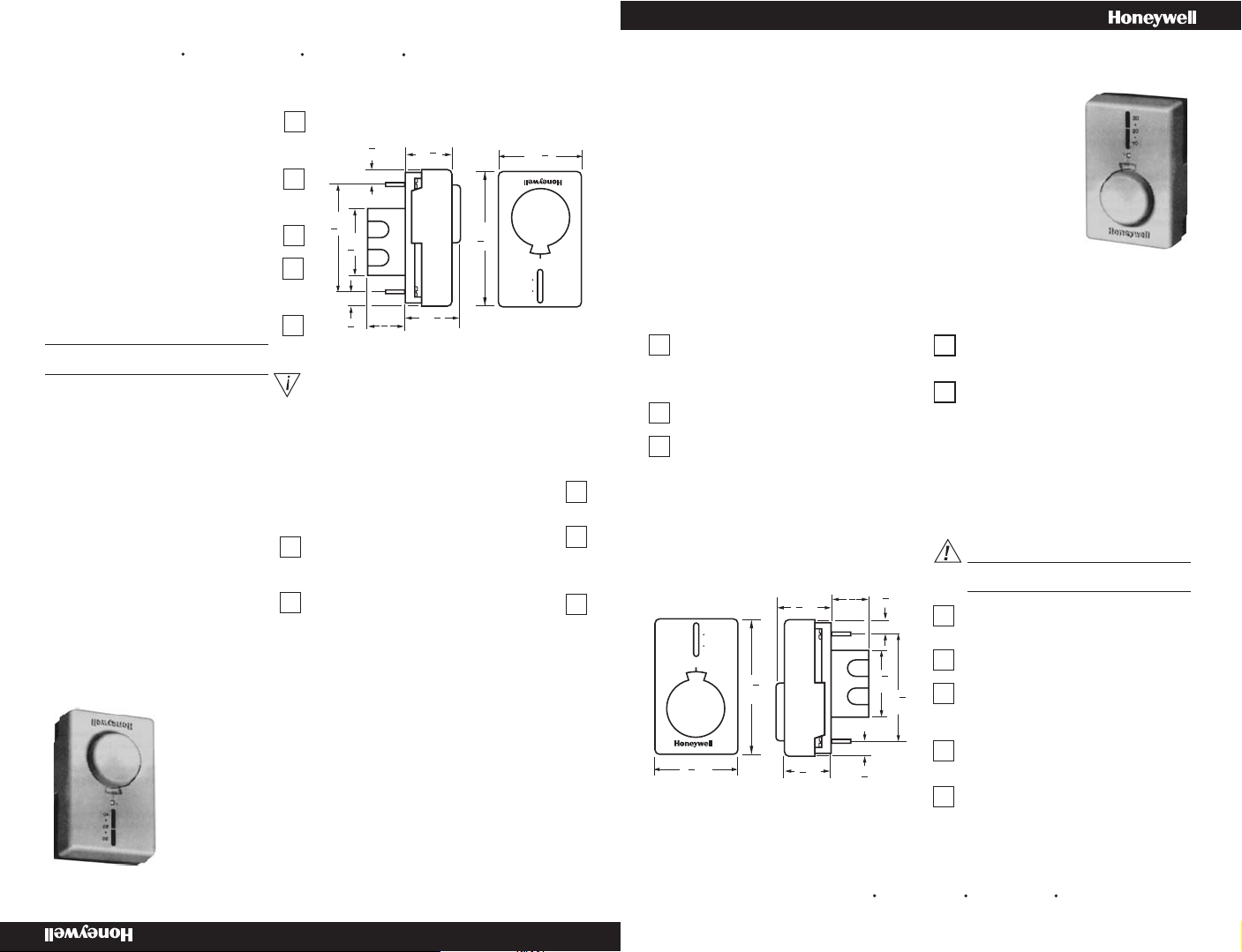
Your new Honeywell CT62 Electric Heating Thermostat provides line voltage control of a radiant cable, electric baseboard,
and resistive-rated fan forced heaters within the ratings listed above.
1
VUE FRONTALE VUE LATÉRALE
STEP. It is recommended that as you read, understand
and complete each step, you check it off with pencil or
pen.
time. If the system does not work, contact your local
electrician for assistance.
2
FRONT VIEW SIDE VIEW
correctement. tout spécialement s'il n'a pas
S'assurer que le système de chauffage fonctionne
dessous pour s'assurer que le thermostat convient
Relire les caractéristiques nominales indiquées ci-
directives ci-dessous sont suivies ÉTAPE PAR
Le thermostat Honeywell sera bien installé si les
ENCOMBREMENT DU THERMOSTAT
PRÉPARATION
2
votre localilé pour obtenir de l'aide.
ne fonctionne pas, communiquer avec un électricien de
tonctionné pendant une période prolongée. Si le système
au système.
comprise et exécutée.
étape au crayon ou au stylo à mesure qu'elle est lue,
ÉTAPE. Nous vous recommandons de cocher chaque
1
ci-dessus.
chauffants, de plinthes électriques et d'appareils de chauffage à air forcé résistils, dans les limiles des capacités indiquées
Votre nouveau thermostat Honeywell CT62 pour chauffage électrique assure la régulation tension secteur de câbles
Votre thermostat Honeywell
Modèles à installer soi-même
22 Aà 120.240 V c.a.; 19Aà 277 V c.a.
Caractéristiques électriques nominales: 60 Hz, non inductif
Gamme de température: 10 à 25° C [50 à 80° F]
Le CT62B est un thermostat à double rupture de courant.
Directives d'installations
Le CT62A est un thermostat à simple rupture de courant.
Thermostats tension secteur pour chauffage électrique
Installation Instructions
CT62A provides single-line break.
CT62B provides double-line break.
Temperature Range: 10 to 25° C [50 to 80° F]
Electrical Ratings: 60 Hz noninductive
22A at 120-240 Vac; 19A at 277 Vac
Do-It-Yourself models
PREPARATION
Proper installation of your Honeywell thermostat will
occur if you follow these instructions STEP-BY-
ü
Check thermostat sullability for your home's system
by reviewing the ratings listed above.
Make certain that your heating system is working,
especially if it has been inoperative for a length of
THERMOSTAT MOUNTING
DIMENSIONS
3
1
30
20
10
°C
[111]
7
[73]
2
8
4
3
4
8
1
3
4
[48]
[19]
1
[39]
2
1
[13]
2
08/98 Printed in Mexico ©Honeywell Inc. Form Number 95C-10866B
Carefully unpack your new thermostat. To avoid
damage to the sensing element, do NOT remove the
thermostat cover until wiring has been completed.
Save packages of screws, instructions, receipt and
proof-of-purchase.
3
REMOVE OLD THERMOSTAT
WARNING
Begin by tuming off power to the heating circuli at
1
[13]
2
1
2
8
[54]
1
3
4
[83]
M5795A
the main service panel.
Remove cover of old thermostat- cover normally
snaps off when pulled firmly from the bottom. If it
resists, check for a screw that locks the cover.
Loosen screws holding thermostat base to outlet box
and lift away.
Disconnect wires from old thermostat. As you
disconnect each wire, tape the end and label II with
the letter of the terminal designation to make reconnection
to new thermostat easier.
Check the old insulation for cracks, nicks or fraying,
and apply high quality plastic tape where necessary
for adequate insulation.
Retain the old thermostat for referance purposes
and until your new thermostat is functioning
smoothly.
Page 2
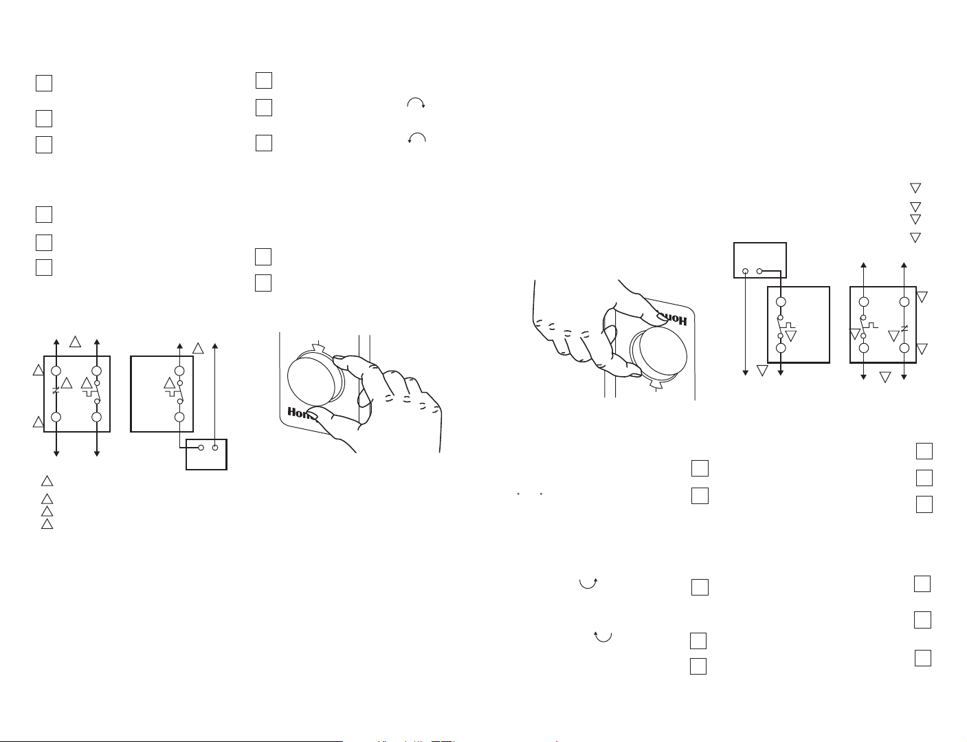
WIRE AND MOUNT NEW THERMOSTAT
4
Turn the temperature setting dial to 20° C. [70° F]
This will prevent accidental damage to the dial
stop during mounting.
Remove thermostat cover by grasping the top and
bottom ends with fingers, and pulling outward.
Connect wires to the thermostat as shown in the
applicable wiring diagram. Push the wires into the
outlet box, and insert the thermostat into the box for
mounting by pushing against top and bottom of the
thermostat base.
IMPORTANT: Do not press on dial indicator knob.
Secure the thermostat to the box with the two
captive mounting screws provided.
Replace thermostat cover.
Set Dial to desired room temperature
IMPORTANT:
3
3
Rough handling or strong pressure can
damage control knob or sensing element, and change
calibration.
L1
1
CT62B
L2
L1
2
44
T1 T1
T2
TO
ELECTRIC
HEATER
1
POWER SUPPLY. PROVIDE DISCONNECT MEANS AND OVERLOAD
PROTECTION AS REQUIRED
2
BREAKS ON POSITIVE OFF
3
EXPOSED UNUSED LEADWIRES TO BE PRQPERL Y INSULATED
4
THERMALLY ACTIVATED-BREAKSON TEMPERATURE
RISE. MAKES ON TEMPERATURE FALL
CAUTION:
SPECIAL SERVICE CO/ALR SOLDERLESS CONNECTORS MUST
BE USED WHEN CONNECTING WITH ALUMINUM CONDUCTORS;
OTHERWISE, A FIRE HAZARD CAN RESULT.
CT62A
(HOT)
L1
1
ELECTRIC
HEATER
95C-10866B
L2
M8420
CHECK OUT THERMOSTAT
5
Turn on the power to the heating system.
Turn setting dial all the way clockwise ; listen
for click sound as switch makes contact. Electric
heater should begin operation.
Turn dial all the way counterclockwise ; listen
for click sound as swich breaks contact. Electric
heater should shut off.
6
SETTING THERMOSTAT
Begin with setting indicator at 20° C [70° F] on
the scale.
If this setting is not satisfactory after at least two
hours of operation, turn setting indicator upscale to
raise the temperature, or downscale to lower the temperature. Move indicator only a degree each time.
°C
20
2
M8422
M8422
2
CT62A
.
T1 T1
4
L1
1
Une manipulation trop brusque ou une
MF8409
ÉLECTRIQUE
DE CHAUFFAGE
APPAREIL
4
L1
1
L2
20
°C
l’indicateur d’un degre à la fois seulement.
vers le bas de l’èchelle pour la diminuer. Déplacer
vers le haut de l’echelle pour augmenter la tempèrature ou
deux heures de fonctonnement, tourner le cadran
Si ce réglage n’est pas satisfaisant après au moins
(HOT)
L1
Commencer par régler le thermostat à 20 C [70 F].
6
RÉGLAGE DU THERMOSTAT
Ne pas appuyer sur le bouton du cadran de
fonctionner.
L'appareil de chauffage électrique devrait cesser de
entendre le déclic qui se produit lorsque le contact s'ouvre.
dans le sens antihoraire ; écouter pour
Faire tourner le cadran de réglege jusqu'au bout
marche.
L'appareil de chauffage électrique devrai! se mettre ne
le déclic qui se produi!lorsque le contact se referme.
dans le sens horaire ; écouter pour entendre
Faire tourner le cadran de réglage jusqu'au bout
Rétablir le courant à l'appareil de chauffage.
VÉRIFICATION DU THERMOSTAT
5
LES RISQUES D'INCENDIE
À DES CONDUCTEURS EN ALUMINIUM AFIN D'ÉVITER
SPÉCIAL CO/AlR LORSQUE LE THERMOSTAT EST RACCORDÉ
UTILISER DES CONNECTEURS SANS SOUDURE POUR SERVICE
AVERTISSEMENT:
BAISSE DE TEMPÉRATURE.
HAUSSE DE TEMPÉRATURE; FERMETURE SUR
DÉCLENCHÉ PAR LA CHALEUR. RUPTURE SUR
DOIVENT ËTRE CORRECTEMENT ISOLÉS.
LES FILS CONDUCTEURS NON UTILISÉS ET EXPOSÉS
RUPTURE SUR COUPUAE DE COURANT.
COUPURE ET UNE PROTECTION CONTRE LES SURCHARGES
ALIMENTATION, FOURNIR, AU BESOIN, UN DISPOSITIF DE
ÉLECTRIQUE
DE CHAUFFAGE
L’APPAREIL
VERS
T2
2
L2
CT62B
Régler le cadran à la température ambiante désirée.
Remettre le couvercle en place.
des deux vis imperdables fournies.
Fixer le thermostat à la boîte de jonction au moyen
schéma de raccordement qui s'applique à votre
Raccorder les fils au thermostat comme l'indique le
par les côtés inférieurs et en le faisant basculer vers
Retirez le couvercle du thermostat en le saisissant
20° C [70° F]. On évitera ainsi d'endommager la
Mettre le bouton de réglage de la température à
CÂBLAGE ET MONTAGE DU
4
3
2
1
3
3
réglage ou l'élément sensible et altérer l'étalonnage.
pression trop forte peuvent endommager le bouton de
IMPORTANT:
réglage.
IMPORTANT :
du thermostat par le haut et le bas.
insérer le thermostat dans la boîte en appuyant sur la base
modèle. Repousser les fils dans la boîte de jonction et
l’extérieur.
butée d'arrêt du cadran pendant l'instailation.
NOUVEAU THERMOSTAT
4
95C-10866B
Page 3

M5796
95C-10866B
DE RÉGLAGE
BOUTON
ANNEAU GRADUÉ
12 HEURES
POSITION
RÉGLAGE À LA
BOUTON DE
3
7
thermomètre du couvercle.
jusqu'à que la position 12 heures corresponde au
l'anneau gradué dans le sens antihoraire
Tenir le bouton fermement et faire tourner
que le contact fasse entendre un déclic.
consigne dans le sens horaire jusqu'à ce
Faire tourner le bouton de réglage du point de
Retirer le couvercle du thermostat.
et la température du thermomètre.
Noter la différence entre la température de conaigne
0
1
2
1
4
1
6
1
2
4
2
8
2
1
2
0
relevé au thermomètre, prendre en note la
Si le point de consigne du thermostat diffère du
si le le contact du thermostat se referme et que la
Il n'est pas nécassaire de réétalonner le thermostat
Réétalonnage :
différence et ré-étalonnez le thermostat comme suit
thermomètre.
température de consigne est la méme que celle du
Le système de chauffage se meltra en marche.
Vértftcatlon de l'étalonnage :
l'étalonnage comme suit :
et qu'il semble toujours être mal étalonné, vérifier
thermostat est installé dans un emplacement qui convient
de température de 0,5 °C [1°F] sont normaux. Si le
réagit à la pression barométrique et à l'altitude. Des écarts
sensible des CT62 à double membrane remplie de vapeur
quelques heures avant de vérifier l'étalonnage. L'élément
réétalonner. Laisser le thennostat fonctionner pendant
contrôlées. Il ne devrait donc pas être nécesseire de les
d'instrument précis et dans des conditions soigneusement
Les thermostats CT62 sont étalonnés à l'usine au moyen
8
ÉTALONNAGE
correspondent pas.
thermomètre ne
et la température au
Le réglage du thermostat
fonctionne sans cesse
L'appareil de chauffage
Absence de chaleur
Symptômes
Le thermostat Honeywell exige peu ou pes d'attention. La plupart des problèmes relèvent de ce qui suit :
7
VÉRIFICATION
Action
THERMOSTAT
SUPPORT DU
avant de vérifier de nouveau l'étalonnege.
Remettre le couvercle en place, et ettendre 5 minutes
membrane de détection de la température.
La chaleur dégagée par les mains fait réagir la
jusqu'au bout
Le thermomètre est mal étalonné.
thermostat.
rayonnante ont un effet sur le
Des courants d'air ou autre chaleur
antihoraire jusqu'au bout.
température dans le sens
Toumer la cadran de réglage de la
Autre.
effectués.
Raccordements du thermostat mal
temperature dans le sens horaire
Toumer le cadren de réglage de la
rétablie au panneau principal.
Assurez-vous que l'alimentation est
Réétalonner le thermostat. Voir l'étape 8.
niveau du sol, sur un mur intérieur.
devrait être situé à environ 1,5 m [5 pl] au-dessus du
changer l'emplacement du thermostat. Le thermostat
Communiquer avec un électricien afin de faire
électricien qualifié.
panneau principal et communiquer avec un
n'est pes le cas, couper l'alimentation électrique au
refroidir dans les deux minutes qui suivent. Si ce
L'appareil de chauffage devrait commencer à se
obtenir de l'aide.
Communiquer avec un électricien qualifié pour
couvercle vers le bas jusqu'à ce qu'il se referme.
resserrez toutes les connexions. Faites basculer le
Une fois coupée l'alimentation électrique au circuit,
chauffage.
qualifié pour taire vérifier le thermostat et l'appareil de
n’est pes le cas, communiquer avec un électricien
réchauffer dans les daux minutes qui suivent. Si ce
L'appareil de chauffage devrait commencer à se
Vérification
TROUBLESHOOTING
Your Honeywell thermostat requires little or no attention. Most problems can generally be traced to the following:
Symptom Checkout Actton
No heat.
Make sure power is on at
main service panel. Turn
the temperature setting diale
fully ciockwise .
Improper connections to
thermostat.
Other.
Heater never turns
off.
Thermostat setting
and thermometer
reading disagree.
CALIBRATION
8
The CT62 Thermostats are calibrated at the factory using
precise instruments under closely controlled conditions.
Recalibration should not be necessary. Allow the thermostat to operate for several hours before checking the
calibration. The CT62 Thermostat vapor-filled dual
diaphragm sensing element is affected by barometric
pressure and altitude. Temperature deviations of 10 F
[0.50 C] are normal. If the thermostat is mounted in a
suitable location and still appears out of calibration, check
calibration as follows:
Check Calibration
Turn the setting knob clockwise until the switch
makes (click sound). The heating equipment will
come on.
No recalibration is necessary If the thermostat switch
makes with the thermostat setting at the same
temperature as indicated on the thermometer.
If the thermostat setting differs from the thermom-
eter, record the temperature difference and
recalibrate as instructed in the Recalibration Procedure
section.
Recalibration Procedure
Note the temperature difference between the
temperature setting and the thermometer.
Turn temperature setting
dial fully
counterclockwise .
Thermostat affected by
drafts or radiant heat.
Thermometer is out of
calibration.
Remove the thermostat cover.
Rotate set point knob clockwise until you hear
switch click.
Hold the set point knob firmly and rotate the set
point scale ring counterclockwise until the
12 o'clock position of the ring agrees with the' cover
thermometer.
Heater should start to warm up within two minutes. If not,
contact qualified electrician to check thermostat and heater.
With power to circuit OFF, tighten all wiring connections. Repair
any frayed or broken wires.
Contact a qualified electrician for assistance.
Heater should start to cool within minutes. If not, turn off power
at the main service panel, and contact qualified electrician.
Contact electrician to change the location. The thermostat
should be about 5 ft [1.5m] above the floor and on an inside
wall.
Recalibrate. See step 8.
The heat from your hand will affect the diaphragm
sensor. Replace thermostat cover, wait 5 minutes
and recheck calibration.
THERMOSTAT
BASE
0
2
1
2
8
2
1
4
2
6
1
4
1
2
1
0
3
SETTING KNOB
AT 12 O’CLOCK
POSITION
SCALE RING
SETTING KNOB
M5796
95C-10866B
Page 4

Honeywell warrants this product to be free from defects in the workmanship or materials, under normal use and service, for a
period of one (1) year from the date of purchase by the consumer, If, at any time during the warranty period, the product is
defective or malfunctions,Honeywell shall repair or replace ii (at Honeywell's option) within areasonable period of time,
If the product is defective,
(i) retum it, with a bill of sale or other dated proof of purchase, to the hardware or home center store from which you
purchased it, or
(ii) package it carefully, alongwith proof of purchase(including date ofpurchase) and a shortdescription of the malfunction,
and mail it,postage prepaid, tothe following address:
Honeywell lnc, RG Department in Canada: Honeywell Consumer Products
1050 BerKshire Lane 510 Bronte St. S.
Plymouth, MN 55441-4437 Milton, ON L9T 2 X 6
This warranty does not cover removal or reinstallation costs. This warranty shall not apply if ij is shown by Honeywell that the
defect of malfunction was caused by damage which occurred while the product was in the possession of a consumer.
Honeywell's sole responsibilijy shall be to repair or replace the product within the terms stated above.
NOT BE LIABLE FOR ANY LOSS OR DAMAGE OF ANY KIND, INCLUDING ANY INCIDENTAL OR CONSEQUENTIAL
DAMAGES RESULTING, DIRECTLY OR INDIRECTLY, FROM ANY BREACH OF ANY WARRANTY, EXPRESS OR IMPLIED
OR ANY OTHER FAILURE OF THIS PRODUCT. Some states do notallow the exclusion of incidentalor consequential dem
ages, so this limi ationmay not applyto you.
THIS WARRANTY IS THE ONLY EXPRESS WARRANTY HONEYWELL MAKES ON THIS PRODUCT. THE DURATION OF
ANY IMPLIED WARRANTIES, INCLUDING THE WARRANTIES OF MERCHANTABILITY AND FITNESS FOR A PARTICULAR PURPOSE, IS HEREBY LIMITED TO THE ONE YEAR DURATION OF THIS WARRANTY. Some states do not allow
limitations on how long an implied warranty lasts, so the above limitation may not apply to your.
This warranty gives you specnic legal rights, and you may have other rights which vary from state to state.
If you have any questions concerning this warranty, please write our Customer Assistance Center, Honeywell Inc.,
P.O. Box 524, Minneapolis, MN 55440-0524 or call 1-800-468-1502, Monday-Friday, 7:00 a.m.-5:30 p.m. Central time.
In Canada write to Honeywell Consumer Products, 510 Bronte Sf. S., Milton, ON L9 T 2 X6.
t
Limited One-Year Warranty
HONEYWELL SHALL
,
-
L9T 2X6.
Centre. Au Canada, écrire à : Produits à la consommation, Honeywell Limitée, 510 Bronte St. S., Milton (Ontario)
524, Minneapolis, MN 55440-0524, ou composer le 1-800-468-1502, du lundi au vendredi, de7hà17h30,heure du
Pour toute question relative à la présente garantie, écrire à : Customer Assistance Center, Honeyweillnc., P.O. Box
varier d'une province à l'autre.
La présente garantie donne au consommateur des droits légaux spécifiques et peut-être certains autres droits qui peuvent
pas de limiter la durée des garanties tacites et, par conséquent, la présente limitation peut ne pas s'appliquer.
PRÉSENTES EXCLUES APRÈS LA PÉRIODE D'UN AN DE LA PRÉSENTE GARANTIE. Certains États ne permettent
GARANTIES DE VALEUR MARCHANDE ET DE CONFORMITÉ À UNE FIN PARTICULIÈRE SONT PAR LES
LA PRÉSENTE GARANTIE TIENT LIEU DE TOUTES LES AUTRES GARANTIES, EXPRESSES OU TACITES, ET LES
peut ne pas s'appliquer.
provinces ne permettent pas l'exclusion ou la restriction des dommages indirects et, par conséquent, la présente restriction
QUELCONQUE D'UNE GARANTIE, EXPRESSE OU TACITE, APPLICABLE AU PRÉSENT PRODUIT. Certaines
INDIRECTS OU ACCESSOIRES DÉCOULANT DIRECTEMENT OU INDIRECTEMENT D'UNE VIOLATION
HONEYWELL N'EST EN AUCUN CAS RESPONSABLE DES PERTES OU DOMMAGES, Y COMPRIS LES DOMMAGES
La responsabilité de Honeywell se limite à réparer ou à remplacer le produit conformément aux modalités susmentionnées.
consommateur l'avait en sa possession.
démontré que la défectuosité ou le mauvais fonctionnement est dû à un endommagement du produit alors que le
La présente garantie ne couvre pas les frais de retrait ou de réinstallation. La présente garantie ne s'appliquera pas s'il est
Plymouth, MN 55441-4437 Milton (Ontario) L9T 2X6
1050 Berkshire Lane 510 Bronte St. S.
R G Department Honeywell Limitée
Honeywell inc. Au Canada: Produits à la consommation,
mauvais fonctionnement, et l'envoyer par la poste, port payé, à l'adresse suivante :
(ii) l'emballer avec soin, accompagné d'une preuve d'achat indiquant la date d'achat et d'une brève description du
qui il a été acheté, ou
(i) le retourner, accompagné d'une preuve d'achat indiquant la date d'achat, au détaillant ou à l'entrepreneur auprès de
Si le produit est défectueux,
dans un délai raisonnable.
mauvais fonctionnement pendant la période de garantie, Honeywell remplacera ou réparera le produit (au gré de Honeywell)
un entretien convenables, et ce, pour une période d'un (1) an à compter de la date d'achat. En cas de défectuosité ou de
Garantie Iimitée d'un an
Honeywell garantit ce produit contre tout vice de fabrication ou de matière dans la mesure où il en est fait une utilisation et
 Loading...