

Page 1
Honeywell
Magic Stat@
CT3100
Microelectronic
HEATING OR HEATING/COOLING
THERMOSTAT
For heating or heating/cooling systems per Table 1, page 2.
INSTALLATION MANUAL
This thermostat may be programmed either before or after installation. If programming before installa-
tion. install a 9 V alkaline battew fwrchase separately) in the thermostat, and refer to Owner’s Manual
f&m number 69.6023 for programming instruciions. .’
Any questions concerning the application of this thermostat should be directed to Honeywell Consumer
Affairs at 1-800-466-1502, Monday-Friday 7:30 a.m.-4:00 p.m.. Central time.
IMPORTANT
S.M.
Rev. o-90
Form Number 69-8024-Z
Honeywell
Inc.
1990
Page 2
P
1
*
W
c
- u)
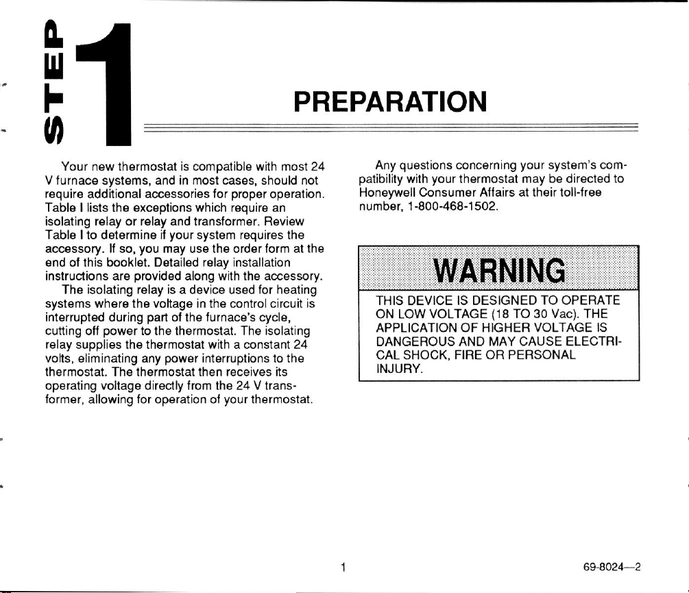
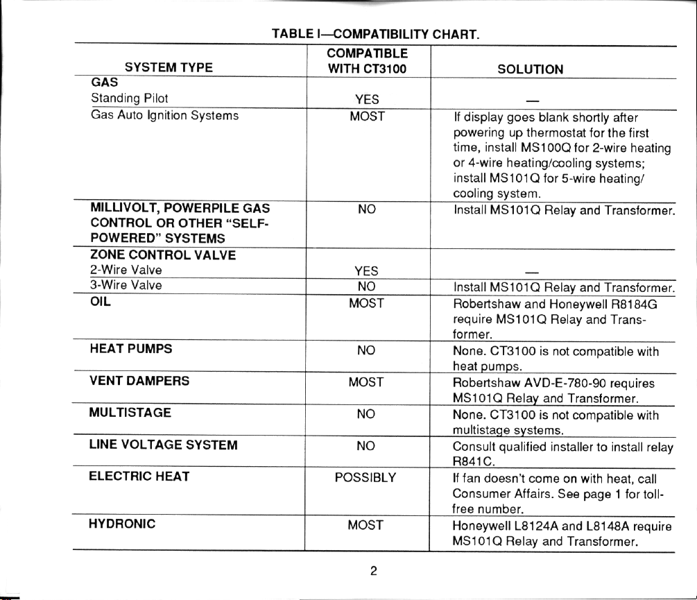
Your new thermostat is compatible with most 24
V furnace systems, and in most cases, should not
require additional accessories for proper operation.
Table I lists the exceptions which require an
isolating relay or relay and transformer. Review
Table I to determine if your system requires the
accessory. lf so, you may use the order form at the
end of this booklet. Detailed relay installation
instructions are provided along with the accessory.
The isolating relay is a device used for heating
systems where the voltage in the control circuit is
interrupted during parl of the furnace’s cycle.
cutting off power to the thermostat. The isolating
relay supplies the thermostat with a constant 24
volts, eliminating any power interruptions to the
thermostat. The thermostat then receives its
operating voltage directly from the 24 V transformer, allowing for operation of your thermostat.
PREPARATION
Any questions concerning your system’s compatibility with your thermostat may be directed to
Honeywell Consumer Affairs at their toll-free
number, l-800-468-1502.
ON LOW VOLTAGE (18 TO 30 Vat). THE
APPLICATION OF HIGHER VOLTAGE IS
DANGEROUS AND MAY CAUSE ELECTRI-
1
INJURY
1
69-8024-Z
Page 3
Page 4
Page 5

Page 6

Page 7

P
4
w
b
WIRE THERMOSTAT TERMINALS
cn
NOTE: All wiring must comply with local codes and
ordinances. If unsure about household wiring
procedures, call Honeywell Consumer Affairs
with your questions Monday-Friday, 7:30 a.m.4:00 pm., Central time, l-800-468-1502.
Refer to notes you made on wire labels when
you remove old thermostat.
Match the letter of your old thermostat wire with
the appropriate letter of your new thermostat
terminal. Refer to figures below and Table II for
additional guidance and typical wire colors for easy
matching. Also note the need to retain or remwe
the factory-installed jumper connected between
terminals RC and R.
TABLE II-TYPICAL WIRE COLORS AND
FUNCTIONS.
aWire colors are typical; verify at heating system
Loosenthe terminal screws, slip each wire
beneath its matching terminals, and tighten
0
screw until all wires have been connected.
6
Page 8

Page 9

Page 10

Page 11

 Loading...