

Page 1

C7089A Outdoor Sensor
INSTALLATION INSTRUCTIONS
APPLICATION
The C7089 Outdoor Sensor is used with the PC8900
Perfect Climate Comfort Center™ Control System and the
W8900 Remote Module. It senses the outdoor temperature for display on the PC8900 at the touch of a key. The
sensor is encapsulated to protect against water and
contaminants, and includes 60 in. leadwires.
SPECIFICA TIONS
Operating Ambient Temperature Range:
-40 to 128°F (-40 to 53°C)
Operating Relative Humidity:
5% to 95% noncondensing
Dimensions in inches (millimeters):
2-1/4 (57) x 3/8 (10) with 60 (1524) leadwires
INST ALLA TION
When Installing this Product…
1 Read these instructions carefully. Failure to follow
them could damage the product or cause a hazardous condition.
2 Check the ratings given in the instructions and on
the product to make sure the product is suitable for
your application.
3 Installer must be a trained, experienced service
technician.
4 After installation is complete, check out product
operation as provided in these instructions.
CA UTION
Disconnect power supply before connecting wiring
to prevent electrical shock or equipment damage.
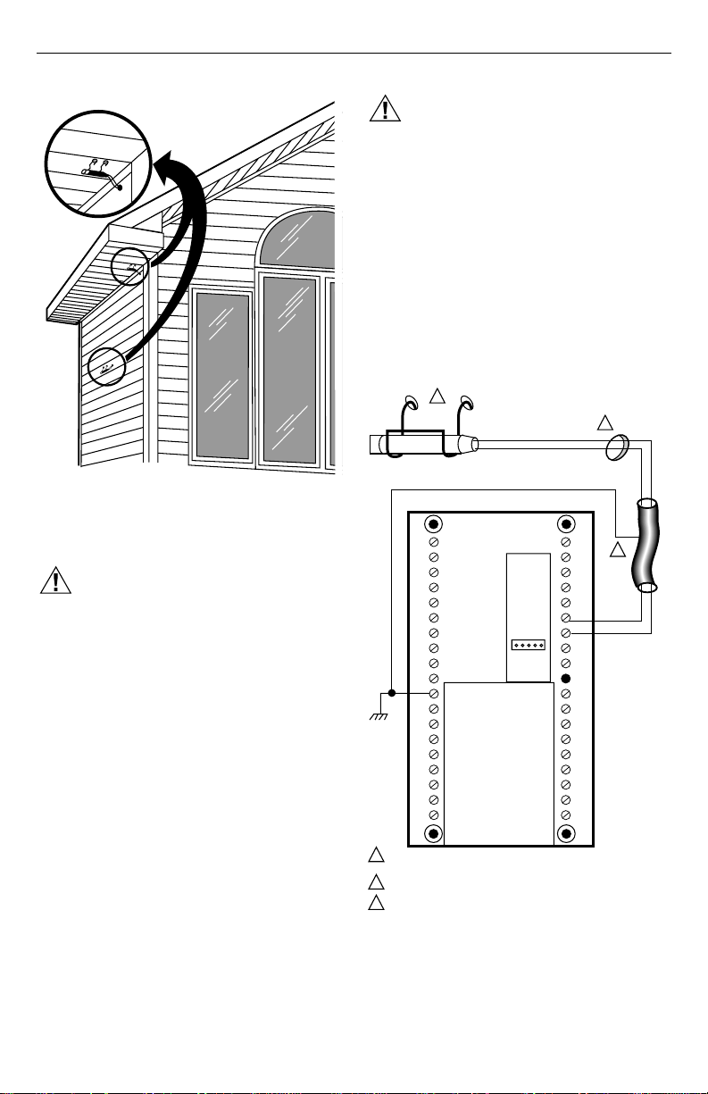
Location and Mounting (Fig. 1)
Mount the sensor where:
• setting can not be tampered with.
• there is good air circulation.
• it can measure the true outdoor ambient
temperature.
• surface is flat.
• the wire distance between the C7089 and W8900 is
less than 200 feet.
Do
not
mount the sensor:
• in the direct sunlight.
• where hot or cold air blows on the sensor. Discharge
line from an outdoor compressor unit, vent or fan will
cause inaccurate temperature readings.
• where snow, ice or debris can cover it.
Use the following steps to mount the sensor:
1 Remove the sensor from the mounting clip.
2 Mark the area on the surface where the C7089
mounting clip will be mounted.
3 Mount the clip.
®U.S. Registered Trademark
Copyright © 1995 Honeywell Inc. • All Rights Reserved
X-XX UL
69-0896-1
Page 2
C7089 OUTDOOR SENSOR
CA UTION
Disconnect the power supply before connecting
the wiring to prevent electrical shock or equipment
damage.
Wiring must comply with applicable codes, ordinances and
regulations.
1 Wire the C7089 Outdoor Sensor to the terminals
marked OUT on the W8900 Remote Module. If the
leadwire provided with the C7089 is not long
enough, run cable to a hole at the selected C7089
location. Color-coded, 18-gauge thermostat wire is
recommended. For an example of general wiring of
the C7089, see Fig. 2. Pigtail wiring can be used.
2 Mount the C7089 in its mounting clip.
3 Plug wiring hole using nonhardening caulk or putty.
Fig. 1. Typical locations for outdoor sensor.
Wiring
CA UTION
Keep wiring at least one foot away from large
inductive loads such as motors, line starters,
lightning ballasts, and large power distribution
panels. Failure to follow these wiring practices can
introduce electrical interference (noise), which can
cause erratic system operation. Use shielded cable
to reduce interference when rerouting is not
possible. Ground the shielded cable to the GND
terminal on the W8900.
IMPORTANT
Erratic temperature readings from a sensor can
occur as a result of any of the wiring practices
described below. These practices must be
avoided to assure proper operation. Use shielded
cable to reduce interference when rerouting of
sensor wiring is not possible.
a. Do not route temperature sensor wiring with
building power wiring, next to control
contactors or near light dimming circuits,
electric motors or welding equipment.
b. Avoid poor wiring connections.
c. Avoid intermittent or missing building earth
ground.
M7514
1
C7089
W8900
OUT
OUT
GND
1
USE APPROPRIATE MOUNTING MEANS FOR THE TYPE
OF STRUCTURE.
2
PLUG WIRING HOLE WITH NONHARDENING CAULK OR PUTTY.
IF SHIELDED CABLE IS REQUIRED, GROUND TO GND TERMINAL
3
ON W8900.
LED
WIRING HOLE
THROUGH
2
STRUCTURE
3
M4457
69-0896—1 2
Fig. 2. Wiring diagram for the C7089 Outdoor Sensor
to the W8900 Remote Module.
Page 3

C7089 OUTDOOR SENSOR
OPERATION
The C7089 Outdoor Sensor converts outdoor ambient
temperature to a resistance that the W8900 Remote
Module can interpret. The W8900 Remote Module in turn
3900
3800
3700
3600
1
3500
3400
3300
OHM RESISTANCE
3200
3100
3000
2900
2800
-40
-20
(-40)
(-29)0(-18)
1
RESISTANCE INCREASES 4.84 OHMS PER 1°F CHANGE OR 8.7 OHMS PER 1°C CHANGE.
M6358
20
(-7)40(5)60(16)80(27)
TEMPERATURE
100
(38)
Fig. 3. C7089A sensor resistance vs. temperature performance characteristics.
sends a signal to the PC8900 where the outdoor temperature is displayed when the CHECK key is pressed. The
C7089 has a positive temperature coefficient (PTC), which
means that the resistance increases as the temperature
increases. Fig. 3 shows the resistance characteristics of
the C7089 Sensor.
OUTDOOR TEMPERATURE
°F °C
-40
-35
-30
-25
-20
-15
-10
-5
0
5
10
15
20
25
30
35
40
45
50
55
60
65
70
140
120
(49)
160
°F
(60)
(79)
(°C )
75
80
85
90
95
100
105
110
115
120
120
130
135
140
145
150
-40.0
-37.2
-34.4
-31.7
-28.9
-26.1
-23.3
-20.6
-17.8
-15.0
-12.2
10.0
12.8
15.6
18.3
21.1
23.9
26.7
29.4
32.2
35.0
37.8
40.6
43.3
46.1
48.9
51.7
54.4
57.2
60.0
62.8
65.6
OHMS OF
RESISTANCE
2929 to 2905
2953 to 2929
2978 to 2953
3002 to 2978
3026 to 3002
3050 to 3026
3074 to 3050
3099 to 3074
3123 to 3099
3147 to 3123
3171 to 3147
3195 to 3171
-9.4
3220 to 3195
-6.7
3244 to 3220
-3.9
3268 to 3244
-1.1
3292 to 3268
1.7
3316 to 3292
4.4
3341 to 3316
7.2
3365 to 3341
3389 to 3365
3413 to 3389
3437 to 3413
3462 to 3437
3486 to 3462
3510 to 3486
3534 to 3510
3558 to 3534
3583 to 3558
3607 to 3582
3631 to 3607
3655 to 3631
3679 to 3655
3703 to 3679
3728 to 3703
3752 to 3728
3776 to 3752
3800 to 3776
3824 to 3800
3849 to 3824
69-0896—13
Page 4

C7089 OUTDOOR SENSOR
CHECKOUT
Allow the C7089 Outdoor Sensor to soak in the outdoor air
for a minimum of five minutes before taking a reading.
With an accurate thermometer (±1°F [0.5°C]), measure the
temperature at the sensor location, allowing time for the
thermometer to stabilize before reading. Press the CHECK
key on the PC8900 until the display shows OUT followed
by the temperature reading. See Fig. 4. The PC8900
reading should match the reading taken outdoors.
To verify the resistance of the sensor, remove one wire
from one of the C7089 wiring terminals. Use an ohmmeter
to measure the resistance across the sensor. Then verify
sensor accuracy with the temperature/resistance curve of
Fig. 3.
CALIBRATION
The C7089 Outdoor Sensor is calibrated in the factory and
cannot be recalibrated in the field.
PC8900
SYSTEM
CHECK
M7515
Fig. 4. Outdoor temperature display on the PC8900.
Home and Building Control
Honeywell Inc.
1985 Douglas Drive
Golden Valley, MN 55422
Home and Building Control
Honeywell Limited-Honeywell Limitée
740 Ellesmere Road
Scarborough, Ontario
M1P 2V9
69-0896—1 4
69-0896—1 J.H. Rev. 6-95 Printed in Mexico
 Loading...