

Page 1
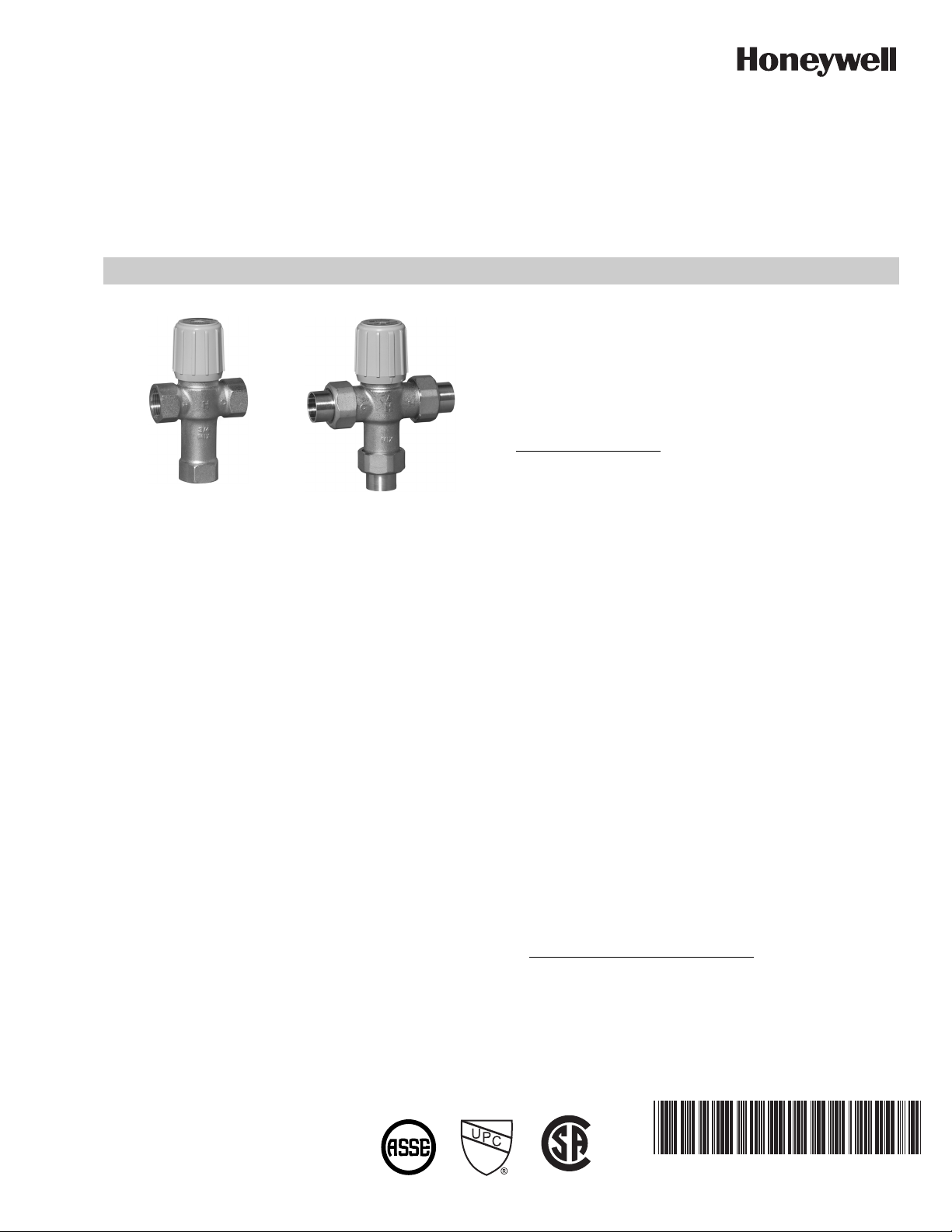
AM-1 Series™
NPT
Union
PROPORTIONAL THERMOSTATIC MIXING AND DIVERTING
VALVE STANDARD AND “C” TEMPERATURE RANGE MODELS NPT, UNION SWEAT, THREAD, CPVC AND PEX MODELS
INSTALLATION INSTRUCTIONS
Patent Information: U.S. Patent No. 6,079,625.
INSTALLATION
APPLICATION
The AM-1 Series™ family of quality valves in a variety of
temperature ranges and connections, for master mixing or
diverting applications.
SPECIFICATIONS
Temperature Range:
C Model: 70°F–120°F (21°C–49°C)
Standard Model: 70°F–145°F (21°C–63°C)
Connections:
Straight-through design (HOT and COLD at same level).
Construction:
Nickel plated brass construction. EPDM o-rings. Made in
USA.
Lead Free Plumbing Code Compliance: The wettable sur-
faces of lead free models contain less than .25% of lead by
weighted average
Operating Pressure: 150 psi (1034 kPa) maximum.
IMPORTANT
NOTE TO INSTALLER:
qualified individual, in accordance with local codes and
ordinances. It is the responsibility of the installer to properly
select, install and adjust these devices as specified in these
instructions. For installations which require compliance with
Building/Mechanical/Plumbing Codes, the appropriate AM-1
Series™ valve must be chosen and installed, and the
discharge temperature set and locked according to these
instructions. AM-1 “C” Series models with the temperature
range, 70°F–120°F (21°C–49°C) and "Standard" models with
temperature range 70°F–145°F (21°C–63°C) are ASSE
1017 (point of source application) certified, and CSA
IAPMO
tubs, showers, bathing facilities and other outlets. These
valves should be installed where they will be accessible for
cleaning, servicing or adjustment.
Mounting must comply with all local codes.
This product should be installed by a
®
®a
®
listed. These models shall be used to supply water to
and
ASSE 1017 Applications—Point of
Source
These AM-1 Series models can be installed in any position
consistent with the intended use. For domestic hot water
supply, the valve must be installed as shown in Fig. 1. There
shall be no shut-off valves installed between the cold water
line and the cold water connection on the AM-1 Series valve.
Check valves shall be installed as indicated for NPT models;
all AM-1 models with union fittings are supplied with integral
check valves on both the hot and cold ports. A cold water
service valve may be installed, as indicated, between the cold
water supply line to the distribution system and the cold water
line supplying both the water heater and the AM-1 Series
valve.
Operating Temperature: 212 °F (100 °C) maximum.
a
-UCPVC and -UPEX models are not CSA listed.
®
CUS
62-3075EFS-03
Page 2
AM-1 SERIES™
WARNING
M25029A
(1)
T
(1)
HEAT
TRAP
6
(152)
8
(203)
MAX
WATER
HEATER
EXPANSION
TANK
ALLOWABLE
SERVICE
VALVE
LOCATION
AM SERIES
WATER USE FIXTURES
RECIRCULATION
PUMP
M
COLD
WATER
SUPPLY
C
V
H
TO DISHWASHER
IF PERMITTED
BY CODES
T
AQUASTAT
(1)
CHECK VALVE
L
1
4
Fig. 1. AM-1 Series ASSE 1017 application
Installation of Union Sweat, CPVC and PEX Connections
— Union sweat connections, if used, should be soldered
prior to assembly to the valve, or without the sealing
gasket or optional check valve present. After the joint
has cooled, the sealing gasket and/or check valves
may be installed.
— CPVC fittings are limited to a system maximum tem-
perature of 180° F (82° C) and 100 psi (689 kPa).
— PEX fitting and crimp ring (provided by Installer) are
deigned to meet ASTM F1807 requirements.
— PEX tubing used with PEX fittings must meet ASTM
F876 requirements.
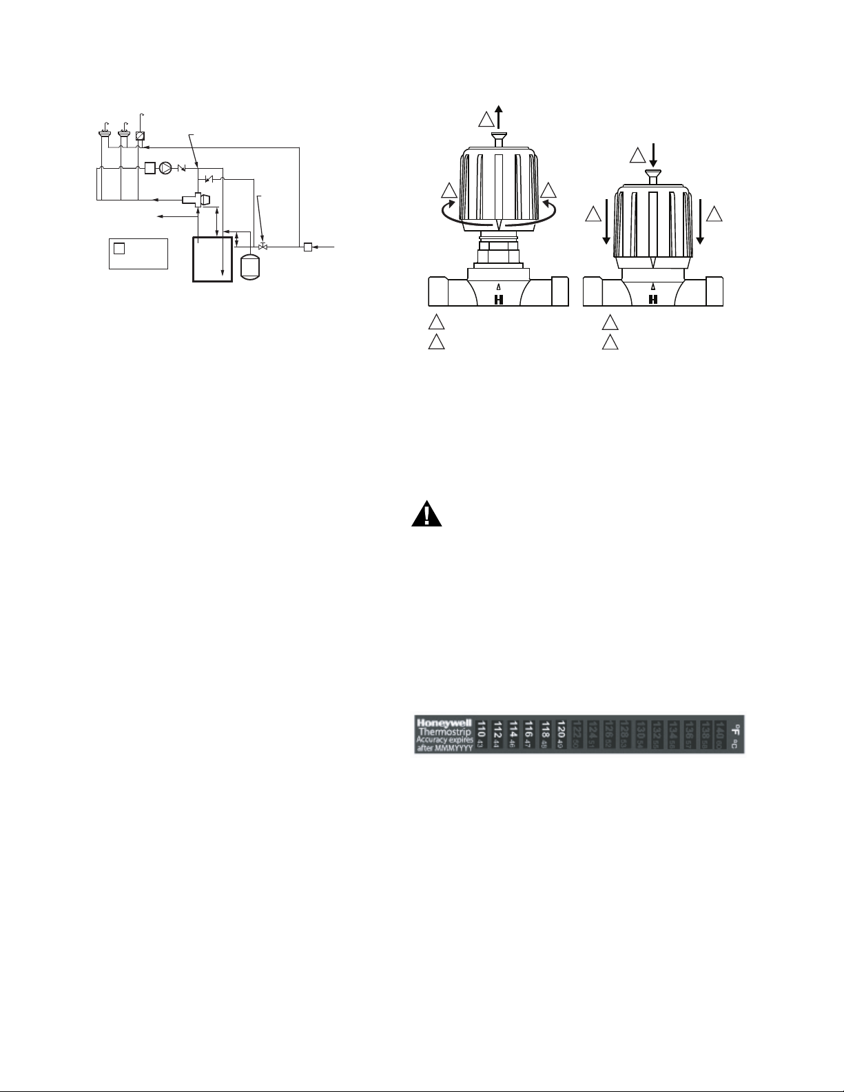
VALVE ADJUSTMENT
To adjust temperature setting of the mixing valve, attach
thermostrip (supplied with the valve) to the piping connected
to the Mix port of the valve. Loosen handwheel screw, lift
handwheel and turn to desired temperature as indicated on
the thermostrip. Reposition the hand wheel and retighten
screw.
2
c
1
LOOSEN SCREW, LIFT HAND WHEEL.
TURN HAND WHEEL CLOCKWISE
2
OR COUNTER CLOCKWISE TO
ADJUST TEMPERATURE.
2
33
H
c
REPOSITION HAND WHEE
3
TO LOCK POSITION.
4
RETIGHTEN SCREW.
H
M27487
Thermostrip Installation
Clean pipe and firmly apply Thermostrip on mix outlet of
valve. Flow water and adjust mixed outlet temperature for
desired setting range. Actual mixed water temperature is
indicated in green with 2° F (1° C) increments. Blue means
slightly lower and brown means slightly higher.
Water Temperature above 120°F (49° C) can cause
serious injury. Mixing valve temperature setting
should be done by licensed contractor per local
code requirement. To ensure correct temperature
control, use water thermometer at faucet outlet.
The thermostrip is ONE TIME USE ONLY for initial system
temperature setting. Check expiration date printed on
temperature strip to ensure temperature reading accuracy. If
necessary, contact your Honeywell distributor to obtain a
replacement thermostrip, part number TS205-064.
Temperature Setting Procedure
It is possible to limit the temperature range. To use this
feature:
62-3075EFS—03 2
Fig. 2. Thermostrip.
Post Installation Procedure
1. Write temperature setting on CAUTION label and sign in
space provided.
2. Attach CAUTION label to AM-1 valve.
3. Explain CAUTION label to owner.
4. Deposit this instruction sheet with owner.
OPERATION
The AM-1 series valve provides for automatic operation
through the use of a thermostatic element in the product. The
element will control the mixing of the hot and cold supply to
Page 3
provide mixed tempered water to connected fixtures. This
provides constant water temperature under different working
conditions.
MAINTENANCE PROCEDURES
AM-1 SERIES™
Table 1. AM-1 Series Replacement Kits
Model Temperature Range Part No.
C 70°–120° F (21°–49°C) AM-1-020 RP
STD 70°–145° F (21°–63° C) AM-1-025 RP
Hard water conditions may result in scale deposits, causing
binding of internal parts in extreme cases. Cleaning the
internal parts will usually restore the valve to proper operating
conditions. In some cases, it may be necessary to replace the
lower assembly.
To clean and/or replace the lower assembly, shut off water
and:
1. With a screwdriver, remove screw and handwheel.
2. Loosen upper nut (do not remove) to allow engaging an
adjustable wrench on lower nut. Unscrew lower nut
(counterclockwise). This removes top assembly.
3. Brass top assembly will pop up. Remove lower assem-
bly, diffuser and spring.
4. Carefully remove any scaling (calcium deposit) or for-
eign particles from valve seat and other internal parts.
Use vinegar to remove calcium. Soak parts until calcium
becomes soft and can be scrubbed and washed off. Do
not use solvents or scratch metallic / Teflon® coated surfaces.
5. Replace cleaned spring, diffuser and lower assembly
following instructions below or use new replacement kit
assembly. For correct kit number, see Table 1.
Install spring, diffuser and lower assembly:
A. Insert spring onto diffuser.
B. Insert diffuser with spring end first into body.
C. Fit valve top assembly into lower assembly and insert into valve.
D. Tighten lower nut.
E. Reposition handwheel and insert screw. Turn handwheel to
desired temperature setting.
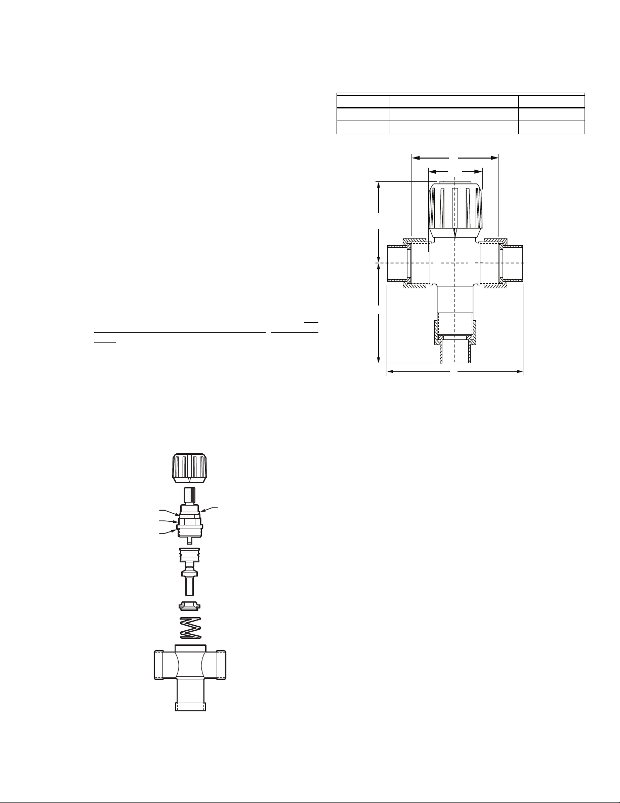
A
Ø 1-51/64
(46)
2-1/4
(57)
H
B
MIX
C
Fig. 4. Dimensions in in. (mm).
C
M23938
HANDWHEEL
UPPER NUT
LOWER NUT
O RING
H
H
MIX
RETAINING RING
TOP ASSEMBLY
LOWER ASSEMBLY
DIFFUSER
SPRING
C
VALVE BODY
M23941
Fig. 3. AM-1 Series valves assembly.
3 62-3075EFS—03
Page 4

AM-1 SERIES™
AM-1 Series™ is a trademark of Honeywell International, Inc.
ASSE® is a registered trademark of the American Society of Sanitary Engineering.
®
CSA
is a registered trademark of the Canadian Standards Association.
®
IAPMO
is a registered trademark of the International Association of Plumbing and Mechanical Officials.
ASTM® is a registered trademark of the American Society for Testing and Materials.
®
Tefl on
is a registered trademark of E.I. du Pont de Nemours and Company.
Automation and Control Solutions
Honeywell International Inc.
1985 Douglas Drive North
Golden Valley, MN 55422
Honeywell Limited-Honeywell Limitée
35 Dynamic Drive
Toronto, Ontario M1V 4Z9
customer.honeywell.com
® U.S. Registered Trademark
© 2010 Honeywell International Inc.
62-3075EFS—03 M.S. Rev. 11-10
Printed in U.S.A.
Page 5

MC
NPT
Union
SÉRIE AM-1
VANNE THERMOSTATIQUE DE MÉLANGE ET DE RÉPARTITION À ACTION
PROPORTIONNELLE À GAMME DE TEMPÉRATURE STANDARD ET «C»,
MODÈLES NPT ET UNION À SOUDER, FILETÉ, ET MODÈLES À RACCORDS
PVC-C ET PEX
NOTICE D’INSTALLATION
APPLICATION
La famille de vannes de qualité de série AM-1MC convenant à
une variété de plages de températures et de systèmes de
branchement pour les applications de mélange et de
répartition.
CARACTÉRISTIQUES TECHNIQUES
Information sur le brevet : Brevet américain n
o
6,079,625.
INSTALLATION
IMPORTANT
REMARQUE À L'INTENTION DE L'INSTALLATEUR : Ce
produit doit être installé par une personne compétente,
conformément aux codes et aux règlements locaux. Il
incombe à l'installateur de choisir correctement, de bien
installer et d'ajuster ces appareils, conformément aux
présentes directives. Dans le cas d'installations qui doivent
être conformes aux codes du bâtiment, de mécanique, de
plomberie, la vanne AM-1 qui convient doit être choisie et
installée et la température à la sortie doit être réglée et
bloquée conformément aux présentes directives. Les modèles
de série AM-1 offrant les gammes de températures suivantes :
21 °C-49 °C (70 °F-120 °F) et 21 °C-63 °C (70 °F-145 °F) sont
certifiés ASSE
répertoriés CSA
alimenter en eau les baignoires, les douches, les installations
de bain et d'autres robinets. Ces vannes devraient être
installées dans un endroit accessible pour le nettoyage,
l'entretien ou l'ajustement.
L'installation doit être conforme à tous les codes
locaux en vigueur.
®
1017 (application au point de source), et sont
®a
et IAPMO®. Ces modèles servent à
Limites de la température :
Modèle C : 21 °C–49 °C (70 °F–120 °F)
Modèle standard : 21 °C-63 °C (70 °F-145 °F)
Connexions :
Conception à passage direct (l'eau chaude et l'eau froide sont
au même niveau).
Construction :
Corps de laiton nickelé. Joints toriques en EPDM. Fabriqué
aux États-Unis.
Conformité au code de plomberie relatif aux installations
sans plomb : Les surfaces soumises à l'eau sont des
modèles sans plomb contenant une teneur en plomb moyenne pondérée inférieure à 0,25 %
Pression de service : 11034 kPa (150 psi) maximum.
Température de service : 100 °C (212 °F) maximum.
Applications ASSE 1017-Au point de source
Ces vannes de série AM-1 peuvent être installées dans
n'importe quelle position qui convient à l'usage prévu. Dans le
cas d'installation pour eau chaude domestique, la vanne doit
être installée comme l'illustre la Fig. 1. Il ne doit y avoir aucun
robinet d'arrêt entre la canalisation d'eau froide et le raccord de
la canalisation d'eau froide de la vanne AM-1. Dans le cas des
modèles NPT, les clapets antiretour doivent être installés selon
les indications; tous les modèles AM-1 dotés de raccords
unions sont livrés avec des clapets antiretour intégraux aux
orifices d'eau chaude et d'eau froide. Il peut y avoir un robinet
de service sur la canalisation d'eau froide, selon les
indications, entre la canalisation de distribution d'eau froide et
le système de distribution et entre la canalisation d'eau froide
qui alimente à la fois le chauffe-eau et la vanne AM-1.
a
Les modèles -UCPVC et -UPEX ne sont pas répertoriés
CSA.
®
CUS
Page 6

SÉRIE AM-1
AVERTISSEMENT
A
MF27487
DESSERRER LA VIS, SOULEVER
LE VOLANT DE MANOEUVRE.
FAIRE TOURNER LE VOLANT DE
MANOEUVRE DANS LE SENS
HORAIRE OU ANTI-HORAIRE POUR
RÉGLER LA TEMPÉRATURE.
1
2
REMETTRE LE VOLANT DE
MANOEUVRE EN PLACE
POUR BLOQUER LA POSITION.
RESSERRER LA VIS.
3
4
33
4
1
2
2
c
H
c
H
MC
PPAREILS CONSOMMANT DE L’EAU
(1)
T
POMPE
SÉRIE AM
VERS LE
LAVE-VAISSELLE
SI LE CODE LE PERMET
AQUASTAT
T
(1)
CLAPET ANTIRETOUR
RECIRCULATION
(1)
C
M
H
8
(203)
MAX
CHAUFFEEAU
PIÈGE À
CHALEUR
(152)
6
EMPLACEMENT
PERMIS POUR
LE ROBINET
DE SERVICE
RÉSERVOIR
D’EXPANSION
ARRIVÉE
D’EAU
FROIDE
V
MF25029A
Fig. 1. Application ASSE 1017 de la vanne AM-1.
Installation des raccords unions à souder, PVC-C et PEX
— Les raccords union à souder, s’ils sont utilisés,
devraient être soudés avant d’être fixés à la vanne, ou
sans que la garniture d’étanchéité ou le clapet antiretour en option ne soit présent. Une fois que le joint est
refroidi, la garniture d’étanchéité et (ou) le clapet antiretour pourront être installés.
— Les raccords de PVC-C ne peuvent servir que dans
les systèmes ou la température maximale est de
82 °C (180 °F) et la pression de 689 kPa (100 psi).
— Le raccord PEX et la bague de sertissage (fournis par
l'installateur) sont conçus pour respecter les exigences de la norme ASTM F1807.
— Les tuyaux PEX employés avec les raccords PEX
doivent PEX doit respecter les exigences de la norme
ASTM F876.
Installation de la bande thermique
Nettoyer la canalisation et appliquer fermement la bande
thermique à la sortie d'eau mélangée. Faire couler l'eau et
ajuster la température à la sortie d'eau mélangée jusqu'à
obtenir la gamme de température souhaitée.
La température réelle de l'eau mélangée apparaît par
incrément de 1 °C (2 °F). Le bleu signifie que la température
est légèrement plus basse, et le brun signifie que la
température est légèrement plus élevée.
AJUSTEMENT DE LA VANNE
À plus de 49 °C (120 °F), l'eau chaude peut causer
des blessures graves. Le réglage de la
Pour régler la température de la vanne de mélange, appliquez
la bande thermique (fournie avec la vanne) au tuyau relié à
l'orifice de mélange de la vanne. Desserrez la vis du volant de
manœuvre, soulevez le volant, puis tournez-le jusqu'à la
température désirée indiquée sur la bande thermique.
température de la vanne de mélange doit être fait
par un entrepreneur autorisé, conformément aux
exigences du code local. Pour assurer une bonne
régulation de la température, placer le
thermomètre à la sortie du robinet.
Remettez le volant de manœuvre en place et resserrez la vis.
La bande thermique est à USAGE UNIQUE et sert au réglage
Réglage du point de consigne de température
Il est possible de limiter la gamme de température. Pour se
prévaloir de cette caractéristique :
initial de la température du système. Vérifiez la date
d'expiration imprimée sur la bande afin de vous assurer de la
précision de la température indiquée. En cas de besoin,
communiquez avec votre distributeur Honeywell pour obtenir
une bande thermique de remplacement (numéro de pièce
TS205-064).
Fig. 2. Bande thermique.
62-3075EFS—03 6
Page 7

SÉRIE AM-1
MC
Après l'installation
1. Inscrire le point de consigne sur l'étiquette de MISE EN
GARDE et apposer votre signature dans l'espace prévu
à cet effet.
2. Fixer l'étiquette de MISE EN GARDE à la vanne AM-1.
3. Expliquer la MISE EN GARDE au propriétaire.
4. Remettre les présentes directives d'installation au pro-
priétaire.
FONCTIONNEMENT
Les vannes de série AM-1 sont conçues pour un
fonctionnement automatique et font appel à un élément
thermostatique intégré à l'appareil. Cet élément
thermostatique commande le mélange de l'eau chaude et de
l'eau froide afin de fournir de l'eau mélangée tiède aux
robinets des appareils sanitaires. L'eau est ainsi acheminée à
température constante peu importe les conditions d'utilisation.
MAINTENANCE
L'eau calcaire peut entraîner des dépôts qui, dans les cas
extrêmes, peuvent faire gripper les pièces internes. Il suffit
généralement de nettoyer les pièces internes pour que la
vanne retrouve son fonctionnement d'origine. Dans certains
cas, il peut être nécessaire de remplacer les pièces
inférieures.
Pour nettoyer et (ou) remplacer les pièces inférieures, couper
l'arrivée d'eau et :
1. À l'aide d'un tournevis, retirer la vis et le volant de
manœuvre.
2. Desserrer l'écrou du haut (sans le retirer) pour pouvoir
insérer une clé à molette autour de l'écrou du bas.
Dévisser l'écrou du bas (dans le sens anti-horaire). On
parvient ainsi à enlever la partie supérieure
3. La partie supérieure en laiton sortira de son logement.
Retirer la partie inférieure, le diffuseur et le ressort.
4. Enlever soigneusement tout dépôt de calcaire ou parti-
cules étrangères du siège de la vanne et des autres
pièces internes. Utiliser du vinaigre pour nettoyer le calcaire. Faire tremper les pièces jusqu'à ce que le calcaire ramollisse et qu'il soit possible de l'enlever en le
frottant et en lavant les pièces. Ne pas utiliser de solvants ou de tampons métalliques ou recouverts de
Te fl o n®.
5. Remettre en place le ressort, le diffuseur et la partie
inférieure en suivant les directives ci-dessous, ou
encore utiliser une trousse de remplacement. Pour connaître le numéro de la trousse de remplacement, consulter le Tableau 1.
Installation du ressort, du diffuseur et de la partie inférieure :
A. Insérer le ressort sur le diffuseur.
B. Insérer le diffuseur dans le corps de vanne, côté ressort en
premier.
C. Faire correspondre la partie supérieure de la vanne à la partie
inférieure et insérer le tout dans la vanne.
D. Resserrer la vis inférieure.
E. Repositionner le volant de manœuvre et insérer la vis. Tourner le
volant de manœuvre au réglage de température voulu.
VOLANT
ÉCROU DU HAUT
ÉCROU DU BAS
JOINT TORIQUE
H
H
MIX
ANNEAU DE RETENUE
PARTIE SUPÉRIEURE
PARTIE INFÉRIEURE
DIFFUSEUR
RESSORT
C
CORPS DE VANNE
MF23941
Fig. 3. Assemblage des vannes de série AM-1.
Tableau 1. Trousses de remplacement pour vanne AM-1.
o
Modèle Gamme de température N
C
21 °C - 49 °C (70 °F - 120 °F) («C»)
de pièce
AM-1-020 RP
STD 38 °C - 63 °C (100 °F - 145 °F) AM-1-025 RP
7 62-3075EFS—03
Page 8

SÉRIE AM-1
2-1/4
(57)
MC
A
Ø 1-51/64
(46)
MIX
C
C
M23938
H
B
Fig. 4. Dimensions en po (mm).
AM-1 SeriesMC est une marque de commerce de Honeywell International Inc.
ASSE® est une marque déposée de l'American Society of Sanitary Engineering.
CSA® est une marque déposée de l'Association canadienne de normalisation.
IAPMO® est une marque déposée de l'International Association of Plumbing and Mechanical Officials.
ASTM® est une marque déposée de l'American Society for Testing and Materials.
Tef lo n® est une marque déposée de E.I. du Pont de Nemours and Company.
Solutions de régulation et d’automatisation
Honeywell International Inc.
1985 Douglas Drive North
Golden Valley, MN 55422
Honeywell Limited-Honeywell Limitée
35, Dynamic Drive
Toronto (Ontario) M1V 4Z9
customer.honeywell.com
® Marque de commerce déposée aux É.-U.
© 2010 Honeywell International Inc.
Tous droits réservés
62-3075EFS—03 M.S. Rev. 11-10
Imprimé aux États-Unis
Page 9

AM-1 Series™
NPT
Union
VÁLVULA TERMOSTÁTICA PROPORCIONAL MEZCLADORA Y DE DESVÍO
MODELOS ESTÁNDAR Y DE RANGO DE TEMPERATURA "C" - MODELOS DE
CONEXIONES PARA NPT, SOLDADURA, ROSCA, COMPRESIÓN, CLORURO DE
POLIVINILO CLORINADO (CPVC) Y POLIETILENO RETICULADO (PEX).
INSTRUCCIONES DE INSTALACIÓN
INSTALACIÓN
IMPORTANTE
El montaje debe cumplir con todos los códigos
locales.
NOTA PARA EL INSTALADOR: Este producto debe instalarse
por una persona calificada, de acuerdo con los códigos y
reglamentos locales. El instalador es responsable de
Seleccionar, instalar y regular estos accesorios de forma
adecuada, tal como se especifica en estas instrucciones. Para
instalaciones en las que se requiere el cumplimiento de
códigos de construcción, mecánicos o de plomería, se debe
escoger e instalar la válvula AM-1 Series™ adecuada, y se
debe fijar y bloquear la temperatura de descarga según estas
APLICACIÓN
La familia de válvulas de calidad AM-1 Series™ se utilizan en
una amplia gama de rangos de temperatura y conexiones,
para mezclas o derivaciones perfectas.
ESPECIFICACIONES
Rango de temperatura:
Modelo C: 70°F a 120°F (21°C a 49°C)
Modelo estándar: 70°F-145°F (21°C-63°C)
Conexiones:
Diseño de conexión directa (CALIENTE y FRÍO al mismo
nivel).
Estructura:
Estructura de bronce niquelado. O-rings de EPDM (juntas
tóricas de monómero de etilen-propilen-dieno). Fabricado
en EE.UU.
Cumplimiento de la normativa de plomería sin contenido
de plomo: Las superficies de los modelos sin contenido de
plomo que reciben humedad contienen menos de 0.25%
de plomo por promedio ponderado
Presión de funcionamiento: 150 psi (1034 kPa) máximo.
Temperatura de funcionamiento: 212 °F (100 °C) máximo.
Información de patente: Patente de EE.UU. No. 6,079,625
instrucciones. Los modelos "C" de la serie AM-1 con rango de
temperatura de 70°F-120°F (21°C-49°C) y los modelos
"estándar" con rango de temperatura de 70°F-145°F (21°C63°C) tienen la certificación ASSE
de origen) y forman parte de la lista CSA
modelos se deben usar para suministrar agua a bañeras,
duchas, instalaciones de baño y otras salidas. Estas válvulas
se deben instalar en lugares en donde serán accesibles para
la limpieza, mantenimiento y regulación.
®
1017 (aplicación en punto
®
a
y IAPMO®. Estos
Aplicaciones ASSE 1017: punto de origen
Estos modelos de la serie AM-1 se pueden instalar en
cualquier posición que se aplique para el uso deseado. Para
suministro de agua caliente en el hogar, la válvula se debe
instalar como se muestra en la fig. 1. No debe haber instalada
ninguna válvula de cierre entre la tubería de agua fría y la
conexión de agua fría en la válvula de la serie AM-1. Se debe
instalar la válvula de retención como se indica para los
modelos NPT, todos los modelos AM-1 con uniones se
suministran con válvulas de retención completas en los
terminales de agua caliente y de agua fría. Se puede instalar
una válvula de servicio de agua fría como se indica, entre la
tubería de suministro de agua fría al sistema de distribución y
la tubería de agua fría que suministra al calentador de agua y
a la válvula de la serie AM-1.
a
Los modelos UCPVC y UPEX no se encuentran en la lista
de CSA.
®
CUS
Page 10

AM-1 SERIES™
ADVERTENCIA
ARTEFACTOS DE USO DE AGUA
RECIRCULACIÓN
1
(1)
AL LAVAPLATO,
SI LO PERMITE
LA REGLAMENTACIÓN
AQUASTAT
T
(1)
VÁLVULA DE RETENCIÓN
T
BOMBA
AM SERIES
(1)
C
M
H
8
(203)
MAX
CALENTADOR
DE AGUA
TRAMPA
DE CALOR
(152)
6
UBICACIÓN
AUTORIZADA
DE LA VÁLVULA
DE SERVICIO
TANQUE DE
EXPANSIÓN
FUENTE
DE AGUA
FRÍA
V
MS25029A
Fig. 1. Aplicación ASSE 1017 de AM-1 Series
Instalación de Conexiones de Soldadura, de CPVC y PEX.
— Si se utilizan conexiones de soldadura, deberían sol-
darse antes de ensamblar a la válvula o sin la junta de
sellado o la válvula opcional de retención. La junta de
sellado y/o las válvulas de retención pueden instalarse
una vez que la unión se ha enfriado.
— Los acoplamientos de CPVC se limitan a una temper-
atura máxima del sistema de 180° F (82° C) y 100 psi
(689 kPa).
— La conexión PEX y el anillo de presión (proporciona-
dos por el instalador) están diseñados para cumplir los
requisitos de la norma ASTM F1807.
— La tubería PEX usada con conexiones PEX debe
cumplir los requisitos de la norma ASTM F876.
AJUSTE DE VÁLVULAS
Para regular el ajuste de temperatura de la válvula
mezcladora, fije el termómetro (suministrado con la válvula) a
la tubería conectada al terminal de mezcla de la válvula.
Afloje el tornillo de la manivela, levante la manivela y gire
hasta alcanzar la temperatura deseada como se indica en el
termómetro. Vuelva a colocar la manivela y ajuste el tornillo
otra vez.
Procedimiento de ajuste de la temperatura
Es posible limitar el rango de temperatura. Para emplear esta
función:
4
2
c
1
SUELTE EL TORNILLO Y
LEVANTE LA MANIVELA.
GIRE LA MANIVELA EN EL SENTIDO
2
DE LAS AGUJAS DEL RELOJ O EN EL
SENTIDO CONTRARIO PARA AJUSTAR
LA TEMPERATURA.
2
33
H
c
VUELVA A COLOCAR LA MANIVELA
3
EN LA POSICIÓN DE BLOQUEO.
4
VUELVA A APRETAR EL TORNILLO.
H
MS27487
Instalación de la Tira Térmica
Limpie el tubo y aplique con firmeza la tira térmica en la salida
mezcladora de la válvula. Haga correr el agua y ajuste la
temperatura de salida al rango deseado. La temperatura real
del agua mezclada se indica en verde con incrementos de 2°
F (1° C). El azul significa que la temperatura es ligeramente
menor y el marrón indica que es apenas mayor.
Temperaturas superiores a los 120° F (49° C)
pueden provocar lesiones serias. Un contratista
con licencia debería fijar la temperatura de la
válvula mezcladora conforme a los requisitos del
código local. Para garantizar un control de
temperatura correcto, utilice un termómetro de
agua en la boca de salida de la llave.
El termómetro es PARA USAR UNA SOLA VEZ para el
ajuste inicial de la temperatura del sistema. Verifique la fecha
de expiración impresa en la banda de temperatura para
asegurarse de la exactitud de la lectura de la temperatura. De
ser necesario, póngase en contacto con su distribuidor
Honeywell para obtener un termómetro de repuesto, número
de parte TS205-064.
62-3075EFS—03 10
Fig. 2. Tira térmica.
Procedimiento Posterior a la Instalación
1. Anote el ajuste de temperatura en la etiqueta de PRE-
CAUCIÓN y firme en el espacio que se proporciona.
2. Pegue la etiqueta de ADVERTENCIA a la válvula AM-1.
3. Explique la etiqueta de ADVERTENCIA al propietario.
4. Deje esta hoja de instrucciones en poder del propi-
etario.
Page 11

FUNCIONAMIENTO
La válvula AM-1 series funciona en forma automática a través
del empleo de un elemento termostático en el producto. El
elemento controlará la mezcla del suministro caliente y frío
para brindar agua templada a las piezas con las que se
conecta. De esta forma, se brinda una temperatura constante
del agua bajo las diferentes condiciones de funcionamiento.
PROCEDIMIENTOS DE MANTENIMIENTO
TUERCA SUPERIOR
TUERCA INFERIOR
JUNTA TÓRICA
AM-1 SERIES™
MANIVELA
ANILLO DE RETENCIÓN
ENSAMBLAJE SUPERIOR
ENSAMBLAJE INFERIOR
El uso de agua dura puede dar como resultado la formación
de depósitos de sarro, lo que provoca el agarrotamiento de
las piezas internas en casos extremos. La limpieza de las
piezas internas restablece generalmente la válvula a las
condiciones de operación normales. En algunos casos, puede
ser necesario reemplazar el ensamblaje inferior.
Para limpiar y/o reemplazar el ensamblaje inferior, corte el
agua y:
1. Con la ayuda de un destornillador, extraiga el tornillo y
la manivela.
2. Suelte la tuerca superior (sin extraerla) para permitir la
colocación de una llave ajustable en la tuerca inferior.
Desatornille la tuerca inferior (en el sentido contrario al
de las agujas del reloj). Ello permitirá la extracción del
ensamblaje superior.
3. El ensamblaje superior de latón saldrá. Extraiga el
ensamblaje inferior, el difusor y el resorte.
4. Elimine cuidadosamente todo sarro (depósito de calcio)
o partículas extrañas del asiento de la válvula y de otras
piezas internas. Use vinagre para remover el calcio.
Moje las piezas hasta que el calcio se ablande y se
pueda raspar y eliminar con el lavado. No use solventes
ni raye las superficies de metal o revestidas con
Te fl o n®.
5. Vuelva a colocar el resorte, el difusor y el ensamblaje
inferior limpios con ayuda de las instrucciones a continuación o use un conjunto de kit de recambio nuevo.
Para conocer el número de kit correcto, consulte la
Tabla 1.
Instale el resorte, el difusor y el ensamblaje inferior:
DIFUSOR
RESORTE
C
H
H
CUERPO DE LA VÁLVULA
MIX
MS23941
Fig. 3. Ensamblaje de las válvulas serie AM-1.
Tabla 1. Kits para reemplazar la válvula serie AM-1.
Modelo Rango de temperatura Pieza No.
C 70° - 120° F (21°-49°C) (“C”) AMP-1-020 RP
STD 100° - 145° F (38° - 63° C) AM-1-025 RP
A
Ø 1-51/64
(46)
2-1/4
(57)
A. Inserte el resorte en el difusor.
B. Inserte el difusor introduciendo en primer lugar el extremo del
resorte en el cuerpo.
C. Coloque el ensamblaje superior de la válvula en el ensamblaje
inferior e inserte en la válvula.
D. Apriete la tuerca inferior.
E. Cambie la ubicación del volante manual e inserte el tornillo. Gire
el volante manual a la graduación de temperatura deseada.
MIX
C
C
M23938
H
B
Fig. 4. Dimensiones en pulg. (mm).
11 62-3075EFS—03
Page 12

AM-1 SERIES™
AM-1 Series™ es una marca de Honeywell International, Inc.
®
es una marca registrada de American Society of Sanitary Engineering.
ASSE
CSA es una marca registrada de Canadian Standards Association.
®
IAPMO
es una marca registrada de International Association of Plumbing and Mechanical Officials.
®
es una marca registrada de American Society for Testing and Materials.
ASTM
®
es una marca registrada de E.I. du Pont de Nemours and Company.
Tefl on
Automatización y control desenlace
Honeywell International Inc.
1985 Douglas Drive North
Golden Valley, MN 55422
Honeywell Limited-Honeywell Limitée
35, Dynamic Drive
Toronto, Ontario M1V 4Z9
customer.honeywell.com
® Marca Registrada en los EE. UU.
© 2010 Honeywell International Inc.
todos Los Derechos Reservados
62-3075EFS—03 M.S. Rev. 11-10
Impreso en EE. UU..
 Loading...