

Page 1
PENTAX Corporation 2-36-9,Maeno-cho, Itabashi-ku, Tokyo 174-8639, JAPAN (http://www.pentax.co.jp/)
PENTAX Europe GmbH (European Headquarters) Julius-Vosseler-Strasse, 104, 22527 Hamburg, GERMANY
PENTAX U.K. Limited Pentax House, Heron Drive, Langley, Slough, Berks SL3 8PN, U.K. (http://www.pentax.co.uk)
PENTAX France S.A.S. 12/14, rue Jean Poulmarch, 95106 Argenteuil Cedex, FRANCE
PENTAX Benelux B.V. (for Netherlands) Spinveld 25, 4815 HR Breda, NETHERLANDS (http://www.pentax.nl)
PENTAX (Schweiz) AG Widenholzstrasse 1 Postfach 367 8305 Dietlikon, SWITZERLAND (http://www.pentax.ch)
PENTAX Scandinavia AB P.O. Box 650, 75127 Uppsala, SWEDEN (http://www.pentax.se)
PENTAX U.S.A., Inc. 35 Inverness Drive East, Englewood, Colorado 80112, U.S.A. (http://www.pentax.com)
PENTAX Canada Inc. 3131 Universal Drive, Mississauga, Ontario L4X 2E5, CANADA (http://www.pentaxcanada.ca)
• Specifications and external dimensions are subject to change without notice.
56752
(HQ - http://www.pentaxeurope.com) (Germany - http://www.pentax.de)
(for Belgium & Luxembourg) Weiveldlaan 3-5, 1930 Zaventem,BELGIUM (http://www.pentax.be)
The CE Mark is a Directive conformity
mark of the European Community.
Copyright © PENTAX Corporation 2003
02-200304 Printed in Philippines
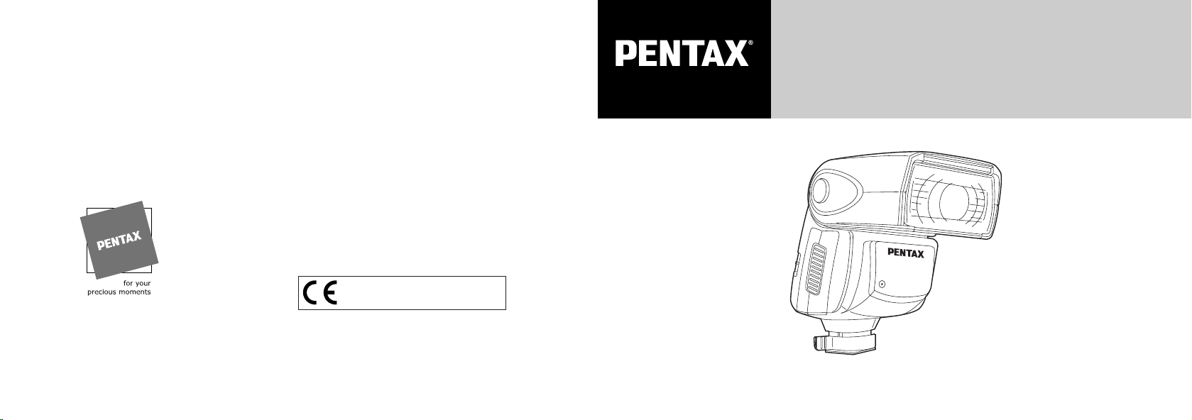
AF360FGZ
AUTO ZOOM ELECTRONIC FLASH UNIT
OPERATING MANUAL
Page 2

Thank you for purchasing the PENTAX Auto-flash AF360FGZ.
In addition to easy daylight sync photography with TTL auto, the AF36OFGZ also allows wireless TTL auto
(P-TTL) photography and high-speed sync. It is clip-on type flash which enable accurate focus adjustments
even in dark locations with built-in AF-assist spotbeam.
Please read this instruction manual carefully first for proper use.
PENTAX is a trademark of PENTAX Corporation.
* The MZ-S is mainly used in the illustrations in these instructions.
Page 3

FOR SAFE USE OF YOUR FLASH UNIT
Although we have carefully designed this flash unit for safe operation, please be sure to follow precautions
given on page 2.
This mark indicates precautions that, if not followed, could result in
WARNING
CAUTION
is a symbol indicating items that are prohibited.
is a symbol emphasizing a warning.
serious injury to the user.
This mark indicates precautions that, if not followed, could result in
minor or medium injury to the user or damage to the equipment.
1
Page 4
PRECAUTIONS FOR YOUR FLASH UNIT
WARNING
The electronic circuits inside the flash contain
high voltage working parts. Never attempt to
disassemble the flash unit yourself.
Never touch internal parts of the flash unit if
they become exposed from dropping the
camera or for some other reason, as there is
danger of an electric shock.
Do not expose the flash unit to water or
moisture. This is to prevent electrical shock.
2
CAUTION
Do not use the flash near anyone's eyes, as it
may hurt them. Be particularly careful with the
flash around infants.
Never try to disassemble, short or recharge
the battery. Also, do not dispose of the battery
in fire, as it may explode.
Misuse of the battery can cause hazards such
as leakage, overheating, explosion, etc. The
battery should be inserted with the "+" and "-"
sides facing correctly.
Remove the batteries from the camera
immediately if they become hot or begin to
smoke. Be careful not burn yourself during
removal.
• When using the flash unit off the camera, do not try to attach any metallic object to the electric
contacts or to mount incompatible accessories. Otherwise, the TTL auto mechanism may be
damaged or rendered inoperable. Use only compatible Pentax accessories.
• Never use solvents such as paint thinner, alcohol or benzene to clean the flash unit.
• Avoid leaving the flash unit for extend period in places where the humidity and temperature are
very high such as in a car.
• Be careful not to subject the flash unit to strong vibrations, shock or pressure. Use a cushion to
protect the flash unit when carrying it in a motorcycle, car, boat, etc.
• Shield the flash unit from salty air and water at the beach, splashing liquid of any kind, and rain.
When the flash unit is subjected to rain or moisture, wipe it off with a dry soft.
• Replace the batteries at the same time. Do not mix battery brands, type or an old battery with a
new one. It may cause explosion or overheating.
• Remove the batteries when not using for extended periods. Leakage of fluids may result and
cause damage to inside of the flash unit.
3
Page 5

TABLE OF CONTENTS
• When mounting the flash unit to the camera's hot shoe, hold the portion near the hot shoe
bracket to avoid damage to the hot shoe, and do not mount/dismount it by force.
• If the unit has not been used for an extended period of time, or is being readied for an important
shoot, it is recommended that you take a test flash with the test button and test shoot with it.
Test flash is also important to maintain optimum performance.
• Manganese batteries are not recommended for use as they provide a lower number of flashes
per set of batteries.
• Battery performance may temporarily be hindered in low temperatures. Batteries should be kept
warm in temperatures below freezing for proper performance.
• Dark or low-reflectance subjects may result in underexposure. Set the camera's exposure
compensation to the + side.
• Do not attach any accessories having the wrong number of electrical contacts for the hot shoe
or grip. Otherwise, TTL auto metering might not work properly.
• When using the AF360FGZ with SF 7 camera, set the flash mode to Auto flash (A) mode.
4
FOR SAFE USE OF YOUR FLASH UNIT.............1
PRECAUTIONS FOR YOUR FLASH UNIT...........3
NAMES OF WORKING PARTS.............................6
INSERTING THE BATTERIES.............................10
NOTES ON THE POWER SUPPLY.....................12
MOUNTING TO CAMERA ...................................13
AF360FGZ FLASH MODES................................14
PICTURE FORMATS AND
FLASH COVERAGE............................................15
DEDICATED FUNCTIONS WITH
THE PENTAX CAMERAS ...................................19
P-TTL AUTO FLASH...........................................22
(with *ist, MZ-S or MZ-L/MZ-6/ZX-L)
TTL AUTO FLASH ..............................................26
AUTO FLASH ......................................................28
MANUAL FLASH.................................................30
HIGH-SPEED SYNC MODE................................32
(with *ist, MZ-S or MZ-L/MZ-6/ZX-L)
CONTRAST-CONTROL-SYNC FLASH ..............35
WIRELESS MODE ..............................................37
(with *ist, MZ-S or MZ-L/MZ-6/ZX-L)
SELECT BUTTON[S]/ADJUSTMENT DIAL
FUNCTIONS ........................................................46
WIRELESS CHANNEL SETTING .......................48
WIRELESS SLAVE MODE SETTING.................49
SLAVE [IN THE MANUAL FLASH MODE].........50
BOUNCE FLASH ................................................52
WIDE-ANGLE PANEL AND CATCHLIGHT
PANEL .................................................................53
MODELING FLASH/TEST FLASH .....................54
SLOW-SPEED-SYNC FLASH ............................54
AF SPOTBEAM...................................................55
TRAILING-SHUTTER-CURTAIN
SYNC FLASH ......................................................56
USING THE AF360 FGZ DETACHED
FROM THE CAMERA ..........................................57
MAJOR SPECIFICATION....................................58
WARRANTY POLICY..........................................60
5
Page 6
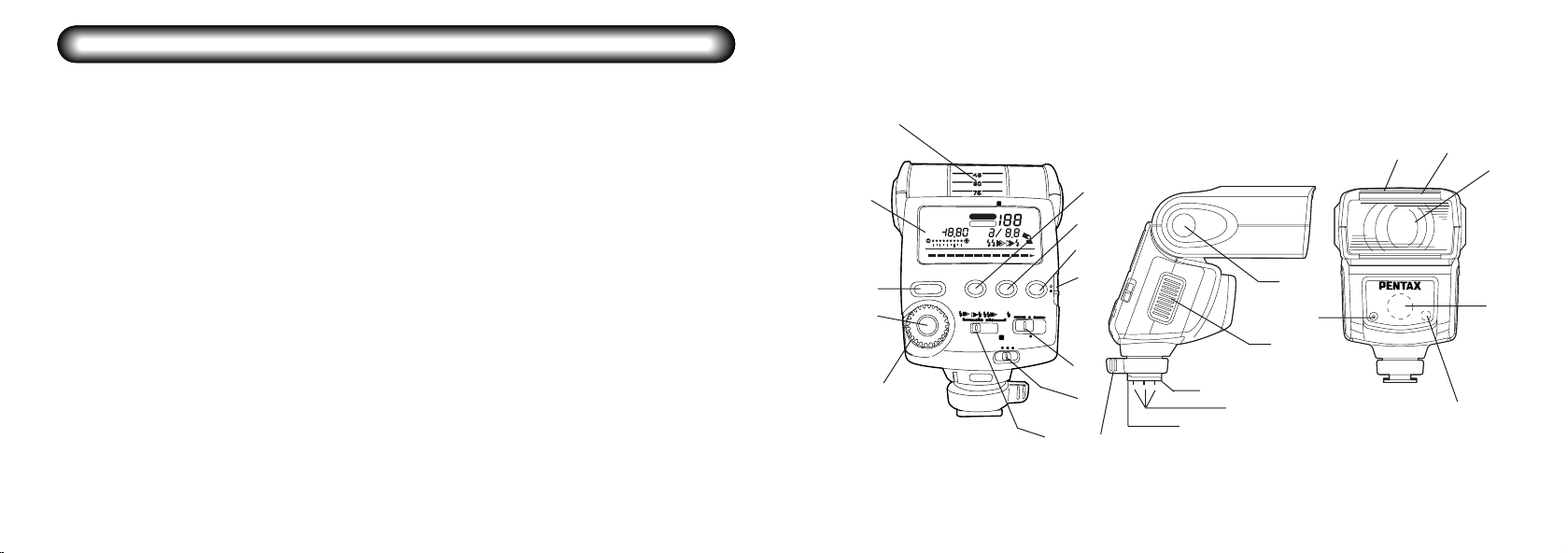
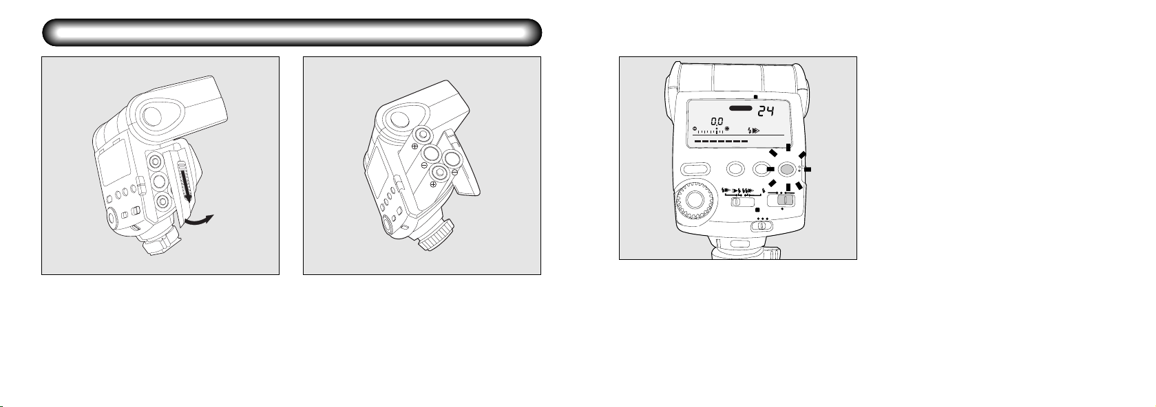
NAMES OF WORKING PARTS
0.7 1 1.5 2 3 4 6 8 12 16 2 2m
2.3 5 10 20 40 70ft
A.Zoom
M.Zoom
mm
CH.
ISO
SB
P-TTLAM
35mm64567
HS
F
MASTER SLAVECONTROL
LIGHT
ZOOM
READY
TEST
FORMAT
CH.
MODELING
HS
OFF
ON
SYNC.
WIRELESS
W
MCS
MODE
FORMAT
W
IRE
LE
S
S
W
S
q Flash head
w AF spotbeam emitter
e Slave sensor
r Auto flash sensor
t Catchlight panel
y Wide - angle panel
u Hot - shoe bracket
i Flash signal contacts
o Shoe lock pin
!0 Locking lever
!1 Battery chamber cover
!2 Bounce lock release button
!3 LCD panel illumination button/Format button
!4 Flash zoom button/Channel button
!5 Test button/Modeling flash button/Ready lamp
!6 Setting switch
!7 Power switch
!8 Wireless mode switch
!9 Sync mode switch
@0 Adjustment dial
@1 Select button
@2 Flash mode button
@3 LCD panel
@4 Bounce angle adjustment
@4
6
5
1
@3
!3
!4
!5
@2
!6
@1
!2
4
2
!1
!7
@0
!8
!9
!0
9
8
3
7
76
Page 7
HS
MODE
0.711.5234681216 22m
2.3 5 10 20 40 70ft
A.Zoom
M.Zoom
mm
CH.
ISO
SB
P-TTLAM
35mm64567
HS
F
MASTER SLAVECONTROL
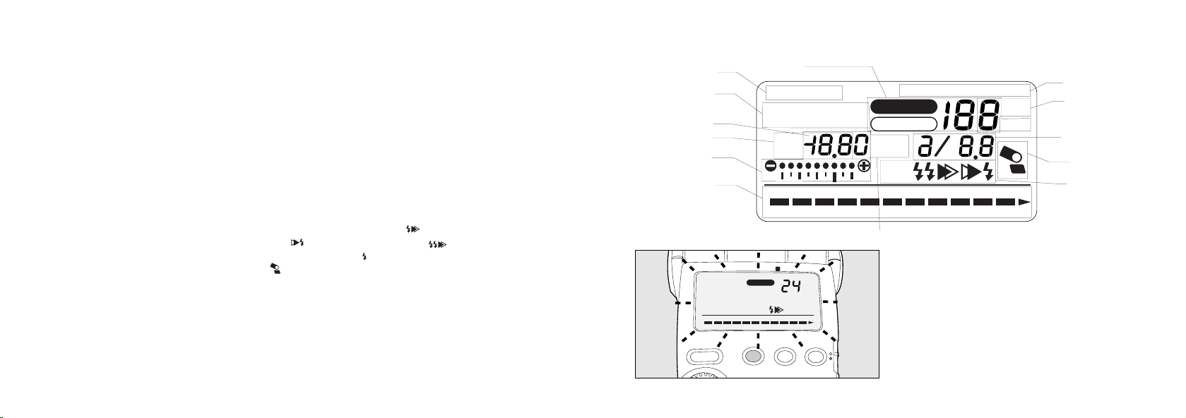
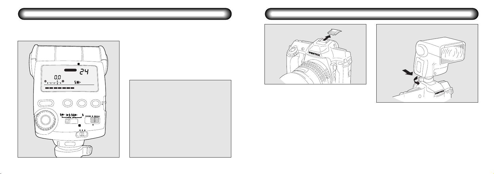
LCD Panel Indication
q5 Zoom indicator
w6 Format display : [35mm] → [645] → [67]
e7 Flash mode display : [P-TTL] → [A] → [M] → [SB]
r9 Flash exposure compensation indicator : [-3.0 ~ +1.0 stops, 0.5 stop increments]
t0 ISO indicator : ISO 25 ~ 1600
y0 Bar graph
u1 Effective flash range indicator :
i0 AF spotbeam : [SB]
o2 Synchronization mode indicator : [Leading-shutter-curtain sync: ] - [Trailing-shutter-curtain
!03 Bounce flash warning : [ ]
!1114 Flash adjustment display : [●● ●● /××]
f/number display : F2 ~ F22
!27 Channel indicator : Channels 1 ~ 4
!38 Wireless mode indicator : [MASTER], [CONTROL], [SLAVE]
: [A Zoom] → [MZoom] xxmm = 20, 24, 28, 35, 50, 70, 85 [35mm format]
35, 45, 55, 70, 100, 135, 150 [645 format]
55, 60, 70, 90, 120, 180, 190 [67 format]
[Closest distance] - [Maximum distance (in P-TTL, TTL, A modes)]
Optimum distance in manual mode
sync: ] - [Contrast-control-sync: ] [High-speed-sync: ]
8
2
3
4
5
6
7
AT
RM
FO
35mm
0.7 1 1.5 2 3 4 6 8 12 16 22m
2.3 5 10 20 40 70ft
MODE
TTL
A.Zoom
LIGHT
FORMAT
ZOOM
W
WIRELESS
CH.
1
mm
READY
TEST
MODELING
!3
!2
!1
!0
9
8
When in poorly lit locations and the display panel
cannot be seen, pressing this button will illuminate
the panel for about 10 seconds. Pressing it again
will turn off the illumination. If the camera’s exposure
meter switch is also ON, the camera’s display panel
will also be illuminated. Additionally, if the camera’s
LCD illumination button is pressed, the AF360FGZ
display panel will also be illuminated.
9
Page 8
INSERTING THE BATTERIES
FORMAT
35mm
A.Zoom
P-TTL
0.7 1 1.5 2 3 4 6 8 12 16 22m
2.3 5 10 20 40 70ft
MODE
LIGHT
FORMAT
S
SYNC.
W
WIRELESS
ZOOM
CH.
HS
W
WIRELESS
MCS
mm
MODELING
OFF
READY
TEST
BATTERIES
This flash unit operates with four AA-size batteries
as shown below.
Alkaline battery : LR6
Lithium battery : FR6
Nickel Hydroxide battery : Ni-MH
The flash unit charges in approximately 6 seconds
with brand new alkaline batteries, 5 seconds with
ON
Nickel Hydroxide battery and 6 seconds with lithium
batteries. If charging time takes more than 20
seconds, then the batteries are weak and should be
replaced with the same type of new batteries.
Slide the battery chamber cover as shown in
the figure to remove.
12
Insert four AA-size batteries, making sure the
plus/minus marking(,,.) match the diagram
inside the battery chamber cover.
10
FIX→
When the power switch is set to the [ON]
position, the Ready Lamp lights up indicating
3
that the flash has been charged and is ready to
fire. Then, by pressing the Test Button, the testflash will fire. Auto check confirmation can be
done in the Auto flash mode but cannot be
done in the TTL or P-TTL mode.
• If the batteries are not inserted properly, the
Ready Lamp will not light up. Insert the
batteries correctly.
• If you let the flash unit fire in succession on
lithium batteries, heated batteries would
activate the safety circuit so that the firing is
temporarily disabled.
In this case, take time to reduce the battery
temperature and it would bring you back to the
normol condition of use.
11
Page 9
NOTES ON THE POWER SUPPLY
Sliding the Power Switch to the ON position will turn ON the power, sliding it to the OFF position will turn OFF
the power.
• Please refer to page 37 for the WIRELESS
MODE position.
• When the power is turned OFF and ON again,
the flash mode will be set to P-TTL and the
FORMAT
35mm
P-TTL
A.Zoom
W
WIRELESS
mm
Zoom position A. Zoom 24mm (35mm
cameras), A. Zoom 45mm (645), and A. Zoom
60mm (67).
MOUNTING TO CAMERA
12
12
0.7 1 1.5 2 3 4 6 8 12 16 22m
2.3 5 10 20 40 70ft
ZOOM
MODE
S
LIGHT
FORMAT
SYNC.
FIX→
HS
W
MCS
CH.
OFF
WIRELESS
READY
TEST
MODELING
ON
Auto Power Off Function
When the flash unit is left unused for about 3
minutes with the power switch set to the [ON]
position, its power automatically switches off to
save on power. To restart charging of the flash
unit, turn ON the power. If the flash unit is
mounted on the autofocus cameras, press the
shutter release button lightly to turn ON the power.
•
The power will shut off after approximately 6
minutes only when set to auto fash mode [A].
• During wireless flash operation, the power
will turn off after about 1 hour of nonoperation.
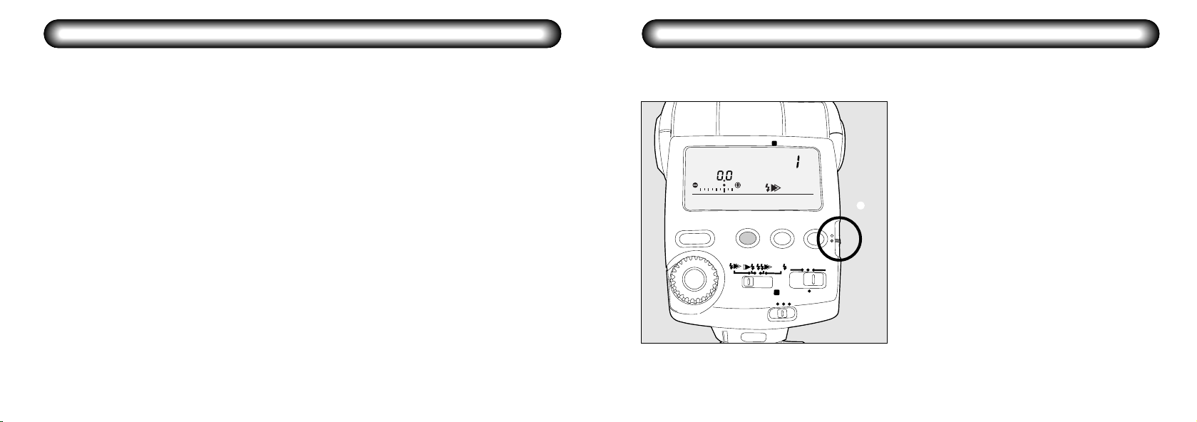
Remove the hot shoe cover from the camera.
1
Slide the shoe bracket into the camera's hot
shoe, then turn the locking lever in the direction
2
of the arrow to secure it in place. To remove it,
loosen the locking lever and slide it off the
camera.
• When the flash unit is attached to the *ist, MZS or MZ-L/MZ-6/ZX-L and the locking lever is
turned toward [FIX →] to lock it, the locking pin
will be extended for secure locking.
• Turn the locking lever in the opposite direction
indicated by [FIX →] before sliding the shoe
bracket into the camera's hot shoe.
• Mount or remove the flash unit to or from the
camera's hot shoe while holding the portion
near the shoe bracket to prevent damage to
the hot shoe.
• The 67II does not come with a hot shoe. The
optional hot shoe grip 67II should be used.
13
Page 10
AF360FGZ FLASH MODES
OFF
PICTURE FORMATS AND FLASH COVERAGE
The AF360FGZ has the following flash modes. Select the mode best suited for the subject.
1P-TTL auto flash [P-TTL]
Works with the Pentax *ist, MZ-S or MZ-L/MZ6/ZX-L camera.
A pre-flash is fired before the main flash fires so
that the multi-segment metering sensor can
measure the subject's distance, brightness,
backlit condition, etc. The data obtained is
incorporated to set the output of the main flash.
This mode obtains more accurate results than
with the conventional TTL mode.
2TTL auto flash [TTL]
Based on the amount of light reflected off the film,
the camera adjusts the flash output automatically
to obtain a correct exposure.
This mode works with all autofocus Pentax
cameras (except *ist, MZ-S and MZ-L/MZ-6/ZXL), LX, Super A, 645N, and 67II.
3Auto flash [A]
The built-in flash metering sensor adjusts the
flash output automatically.
Use with cameras that are not P-TTL or TTL Auto
flash compatible.
4Manual flash [M]
Use the flash unit's Guide No. to calculate the
correct flash range and aperture. This mode
works with all Pentax cameras.
5AF spotbeam beam [SB]
Under low-light or low-contrast conditions, a red
AF-assist beam is emitted to enable
autofocusing. The flash will not fire. This works in
tandem with a Pentax autofocus camera.
14
The AF360FGZ's flash coverage can be adjusted with the auto or manual zoom head to suit the camera's
picture format (35mm, 6x4.5 cm, or 6x7 cm) and lens focal length. Follow the procedure below.
Camera Format Size: [FORMAT] setting
1
35mm
FORMAT
W
P-TTL
0.7 1 1.5 2 3 4 6 8 12 16 22m
2.3 5 10 20 40 70ft
ZOOM
MODE
S
LIGHT
FORMAT
SYNC.
WIRELLESS
CH.
OFF
HS
W
WIRELLESS
MCS
CH.
READY
TEST
MODELING
ON
123
q Slide the setting switch down [yellow dot].
w Press the [FORMAT] button and set to the
camera format size being used.
e Slide the setting switch back up [white dot]
when complete.
• When used with *ist, MZ-S or MZ-L/MZ-6/ZX-L
camera, the format size will automatically be
set when the shutter release button is pressed
halfway down. For all other cameras, set
accordingly before using.
15
Page 11

MODE
35mm
P-TTL
MODE
S
FORM
Setting the flash coverage
With the setting switch set to the [white dot],
2
press the ZOOM button to set the suitable flash
coverage matching the lens focal length.
W
A.Zoom
M.Zoom
LIGHT
FORMAT
SYNC.
WIRELESS
ZOOM
CH.
HS
W
WIRELESS
MCS
mm
MODELING
OFF
READY
TEST
q Auto Zoom (Auto lighting angle adjustment):
A.Zoom
M.Zoom
1
2
[A. Zoom]
When autofocus cameras are used with FA J,
FA, F or FA645 lenses, the appropriate
lighting angle will be automatically set.
• Auto Zoom will not function when set to Auto
Flash [A].
ON
• When using with Auto Zoom, make sure that
[A. Zoom] is shown on the display panel.
w Manual Zoom (Manual light angle
AT
• In the manual zoom mode, refer to the LCD
panel and set it so the flash coverage matches
the lens focal length or set a flash coverage
that is shorter than the lens focal length.
* With the wide-angle panel.
35mm camera 645 camera 67 camera
20mm 35mm 55mm
***
24mm 45mm 60mm
28mm 55mm 70mm
35mm 70mm 90mm
50mm 100mm 120mm
70mm 135mm 180mm
85mm 150mm 190mm
adjustment): [M. Zoom]
When using lenses that are not Auto Focus
compatible (A lenses, A645 lenses, 67
lenses, etc.), adjust the lens focal length
manually.
• When the wide - angle panel is used, the zoom
button will not work. (The wide-angle panel is
in a slit on the top of the flash head. Pull it out
so that it covers the front of the flash head. If
the catchlight panel is not necessary, leave it
in the slit.)
16
17
Page 12

DEDICATED FUNCTIONS WITH THE PENTAX CAMERAS
A.Zoom
M.Zoom
M.Zoom
M.Zoom
M.Zoom
M.Zoom
M.Zoom
A.Zoom
M.Zoom
M.Zoom
M.Zoom
A.Zoom
M.Zoom
M.Zoom
M.Zoom
M.Zoom
M.Zoom
M.Zoom
M.Zoom
M.Zoom
M.Zoom
35mm Camera 645 Camera 67 Camera
18
• In the [A.Zoom] mode, the flash head will zoom
automatically to suit the lens focal length
when you press the shutter button halfway to
turn on the exposure meter.
• If [M.Zoom] is used with an autofocus lens (FA J,
FA, F, or FA645 lens), the focal length on the
LCD panel will blink if the flash coverage set
manually does not suit the lens focal length.
• In the [A.Zoom] mode, if there is no lens focal
length information, the flash coverage will be
set automatically to 24mm with a 35mm
camera. With a 645 camera, it will be set to
45mm, and with a 67 camera it will be 60mm.
• When using the wide-angle panel with 35mm
cameras, fix the setting for both A. Zoom and
M. Zoom to 20mm, to 35mm for 645 camera,
and to 55mm for 67 camera.
With the AF360FGZ used with on Pentax autofocus cameras or 67II camera, the "dedicated" functions are as
shown in the table below work.
Table of the Dedicated Functions
Flash Mode TTL Auto Flash Auto Flash*2 Manual Flash*3
Camera type Type A Type B Type A Type B Type A Type B
TTL Auto Flash ●●*1 ●●*4 ××××
Trailing-Curtain-Sync Flash ●● ●● *4 ××××
Slow-Speed-Sync Flash ●● ●● *4 ●● ●● ●● ●●*4
High speed sync ●● × ××××
Auto Switch to Flash sync Speed (X) ●● ●● ●● ●● ●● ●●*4
Flash Ready Confirmation Signal
through the Viewfinder
Auto Check Confirmation Signal
in the Viewfinder
●● ●● ●● ●● ●● ●●*4
●● ●● ××××
Slave Flash Discharge ●● × ●● ●● ●● ●●*4
Wireless control flash ●● × ××××
AF Spotbeam ●● ●● *5 ××●● ●●*5
Type A: *ist, MZ-S, and MZ-L/MZ-6/ZX-L.
Type B: All Autofocus cameras (except: *ist, MZ-S, MZ-L/MZ-6/ZX-L), 67II.
*1: P-TTL auto flash
*2: Can be selected when the camera is set to the manual exposure mode or exposure meter of the camera is off.
*3: When the camera exposure mode is set to other than manual, it will automatically switch to P-TTL or TTL auto flash.
*4: Except SF7 camera
*5: Except SF7 and 67II cameras
19
Page 13

1. COMBINATION OF EXPOSURE MODES WITH AF360FGZ (All autofocus cameras*1)
Camera's Flash Leading- Trailing- Contrast- Slow-
exposure mode mode curtain-sync curtain-sync control-sync*7 speed-sync
Programmed AE
[Hyper Program*2]
Shutter-Priority AE
in Hyper Program*2
Aperture-Priority AE
in Hyper Program*2
Shutter-Priority AE TTL*3 X-sync
Aperture-Priority AE
Metered Manual
Bulb Exposure
*1: Excluding the *ist, MZ-S, MZ-L/MZ-6/ZX-L, Z-10, SF series *2: Only Z-1, Z-1P, Z-5 and Z-5P.
*3: Will automatically switch to TTL autoflash even when flash is set to manual [M]. When the camera exposure switch is on, auto mode
cannot be selected and only P-TTL auto flash will be valid.
*4: The low speed limit of the shutter speed will change according to the focal length of the lens being used.
*5: The low speed limit of the shutter speed will change according to the surrounding lighting.
*6: Sync speed will be 1/125 sec or less for cameras with flash sync speeds of 1/250 sec
*7: Only possible with built-in flash (possible with 645N)
• For trailing curtain-sync and contrast control-sync, TTL auto flash will be selected even when the flash is set to manual.
• The trailing curtain-sync and contrast control-sync display will be shown only when the camera exposure switch in on and
the shutter button is pressed halfway down.
• The functions for Hyper Manual when the IF button is pressed are identical to when the camera exposure mode is in
Programmed AE.
• Set the wireless slave mode to SLAVE2 when using a slave flash. (Refer to page 49.)
• When using with SF 7, TTL auto flash and Manual flash will not work. (Refer to page 27.)
Autofocus
camera*1
slower than 1/125~1/60 1/60 sec 1/60 sec
TTL*3 X-sync
speed *4
slower than 1/60 sec 1/60 sec
TTL*3 X-sync — — or slower – or slower – ●● – ×
speed *5 *5, *6 *5
slower than 1/60 sec 1/60 sec
TTL*3 X-sync
speed *4 *4, *6
slower than 1/125~1/60 1/60 sec 1/60 1/60 sec
speed
slower than 1/125 1/60 sec 1/60 1/60 sec
TTL*3 X-sync
speed *4 *4, *6 series *4
TTL, A slower than
M X-sync
TTL, A, M
speed or slower *6 slower slower
●● ●● ●● ●● ●● ●● ●● ●● ●● ●●
Z-10/ SF
PZ-10 series
1/100
1/100 or
slower
[1/100 or slower 1/60 or slower 1/60 ×××
~1/60]
—
—
[1/100 or slower only SF or slower – ●● ××
~1/60]
—
[1/100] or slower only SF or slower – ×××
Flash sync 1/60 sec 1/60 1/60 sec *8 1/60
speed or slower or or slower sec or ●● ●● ●●
Autofocus
camera*1 camera*1
— or slower – or slower – ×××
Z-10
Autofocus Z-10
*4, *6 *4
*6 series *4
Autofocus
camera
Z-10/SF
series
Slave
dis-
charge
2. COMBINATION OF EXPOSURE MODES WITH AF360FGZ (*ist, MZ-S, MZ-L/MZ-6/ZX-L)
Camera's Flash Leading- Trailing- Contrast- Slow-speed High-speed
exposure mode mode curtain-sync curtain-sync control-sync -sync sync
Programmed AE P-TTL
Shutter-Priority AE P-TTL
Aperture-Priority AE P-TTL
Metered Manual P-TTL, A, M
Bulb Exposure P-TTL, A, M ●● ●● ●● ●● × ●●
*1: Will automatically switch to P-TTL autoflash even when flash is set to manual [M]. When the camera exposure switch is on, auto flash
cannot be selected and only P-TTL auto flash will be valid.
• For trailing curtain-sync and contrast control-sync, P-TTL auto flash will be selected even when the flash is set to manual
when the shutter is pressed halfway down.
• Set the wireless slave mode to SLAVE1 when using a slave flash. (Refer to page 49.)
Flash sync speed 1/90 sec. 1/60 sec
*1
*1
*1
or slower or slower or slower
Flash sync speed 1/90 sec. 1/60 sec
or slower or slower or slower
Flash sync speed 1/90 sec. 1/60 sec.
or slower or slower or slower
Flash sync speed 1/90 sec. 1/60 sec.
or slower or slower or slower
××●●
●● ●● ●●
× ●● ●●
●● ●● ●●
Wireless
3. COMBINATION OF EXPOSURE MODES WITH AF360FGZ (67II)
Camera's Flash Leading- Trailing- Contrast- Slow-speed
exposure mode mode curtain-sync curtain-sync control-sync -sync
Aperture-Priority AE TTL MANUAL
Metered Manual TTL MANUAL
Bulb Exposure TTL MANUAL ●● ●● ●● × ●●
• With trailing-curtain flash sync and contrast-control-sync, TTL auto flash will be set automatically even if the flash unit is set
to M (Manual).
• The trailing-curtain flash sync and contrast-control-sync will be displayed only when the shutter release button is pressed
halfway down to turn on the exposure meter.
• For slave flash, set the wireless slave mode setting to SLAVE2. (Refer to page 49.)
1/30 sec. 1/15 sec. 1/15 sec
1/30 sec. 1/15 sec. 1/15 sec
or slower or slower or slower
××
●● ●●
Slave discharge
2120
Page 14

P-TTL AUTO FLASH (WITH *ist, MZ-S, MZ-L/MZ-6/ZX-L)
FORMAT
WIRELLESS
W
2.3 5 10 20 40 70ft
0.7 1 1.5 2 3 4 6 8 12 16 22m
A.Zoom
mm
TTL
35mm
FORMAT
35mm
P-TTL
0.7 1 1.5 2 3 4 6 8 12 16 22 m
2.3 5 10 20 40 70ft
MODE
2
FORMAT
S
22
3
A.Zoom
LIGHT
SYNC.
4
W
ZOOM
MCS
WIRELESS
CH.
OFF
HS
W
WIRELESS
mm
READY
TEST
MODELING
ON
5
A pre-flash is fired before the main flash so that the
multi-segment metering sensor can measure the
subject's distance, brightness, backlit condition, etc.
The data obtained is incorporated to set the output
of the main flash. This mode obtains more accurate
results than with the conventional TTL mode.
■ Procedure
Turn on the camera.
1
Turn on the flash unit.
2
Set the sync mode switch to the leadingshutter-curtain sync [ ].
3
• After turning the power [ON], the setting will
be [P-TTL] and [A.Zoom].
With an autofocus lens FA J, FA and F,
[A.Zoom] will be displayed on the LCD panel.
4
With a manual zoom lens, set the focal length
manually at [M. Zoom].
Check the effective flash range and that the
flash is ready. Then take the picture.
5
When a correct flash exposure is obtained, it
will be indicated by the flash confirmation
6
indicator. (In the camera's viewfinder, the [ ]
symbol will blink several times, and [P-TTL] on
the LCD panel will also blink for 2 sec.)
If the flash confirmation indicator does not
blink, it means the flash was insufficient. Move
7
closer to the subject and take the picture again.
If you are too close to the subject, the correct
flash exposure will not be obtained even if the
8
flash confirmation indicator blinks. Be sure to
check the effective flash range on the LCD
panel.
• If necessary, an exposure compensation
amount can be set between +1.0 to -3.0 stops
in 0.5-stop increments.
• Cameras other than *ist, MZ-S, MZ-L/MZ-6/ZX-L
will display P-TTL but are not compatible with
P-TTL. Please use the auto flash mode. (Refer
to page 28)
Display of Flash Effective Range
The shooting distance parameters will be displayed
on the LCD panel. Make sure that you are within the
flash effective range before taking pictures.
• The effective flash range is displayed when all
autofocus cameras (except SF series
cameras) attached with an FA J, FA, F or A lens
and the Pentax 645N and 645NII. If the
maximum range exceeds 22 meters (70 ft), [ ]
will blink. If the flash effective range is 0.7m or
less, [ ] will blink.
• The flash effective range varies depending on
a ISO film speed, lens aperture in use, and/or
the zooming position ( flash coverage angle ).
When using a zoom lens, keep in mind the
maximum aperture of the zoom lens changes
when the lens zooms in and out.
23
Page 15

When Using the "A" ( AUTO ) Lens Aperture
Programmed TTL Auto Flash is possible with the
AF360FGZ when the Programmed AE or ShutterPriority AE mode is set on a camera. The flash sync
speed and aperture values automatically vary
depending on the subject brightness as with the
When Setting the Lens to a Manual f/stop
When the Aperture-Priority AE or Metered Manual
mode is set on the camera, TTL Auto Flash is
possible with the desired aperture selected to
control the depth-of-field. The slow-speed-sync
flash is also possible.
camera's built-in flash, making it suitable for daylight
sync flash.
Calculating the Flash Effective Range
When setting the lens to manual f/stop, calculate the guide number at FULL output strength with the use
of flash's zooming position and film speed. Divide the resulting guide number by the aperture in use. Thus,
the maximum distance is obtained. The minimum distance is obtained in dividing this max. distance by
approx. 10.However, if the shortest distance desired is 0.7m or less, the shortest distance will be 0.7m.
Example :
With ISO100 film and a 50mm lens at f/4
q For the zoom position = 50mm, and film speed at ISO100, the guide number is 30.
w The aperture is f/4, 30 ( guide number )/4 ( aperture ) = 7.5m ( max. distance )
e 7.5m ( max. distance )/10 = 0.75m ( min. distance ) Thus, flash effective range is approx.0.75m - 7.5m.
P-TTL and TTL Auto Flash Effective Range
Format
35mm 20mm 24mm 28mm 35mm 50mm 70mm 85mm 20mm 24mm 28mm 35mm 50mm 70mm 85mm
645 35mm 45mm 55mm 70mm 100mm 135mm 150mm 35mm 45mm 55mm 70mm 100mm 135mm 150mm
67 55mm 60mm 70mm 90mm 120mm 180mm 190mm 55mm 60mm 70mm 90mm 120mm 180mm 190mm
f / 1.2 1.2~11.7 1.8~17.5 1.8~18.3 2.1~20.8 2.5~25.0 2.8~27.5 3.0~30.0 2.3~23.3 3.5~35.0 3.7~36.7 4.2~41.7 5.0~50.0 5.5~55.0 6.0~60.0
f / 1.4 1.0~10.0 1.5~15.0 1.6~15.7 1.8~17.9 2.1~21.4 2.4~23.6 2.6~25.7 2.0~20.0 3.0~30.0 3.1~31.4 3.6~35.7 4.3~42.9 4.7~47.1 5.1~51.4
f / 2 0.7~7.0 1.1~10.5 1.1~11.0 1.3~12.5 1.5~15.0 1.7~16.5 1.8~18.0 1.4~14.0 2.1~21.0 2.2~22.0 2.5~25.0 3.0~30.0 3.3~33.0 3.6~36.0
f / 2.8 0.7~5.0 0.8~7.5 0.8~7.9 0.9~8.9 1.1~10.7 1.2~11.8 1.3~12.9 1.0~10.0 1.5~15.0 1.6~15.7 1.8~17.9 2.1~21.4 2.4~23.6 2.6~25.7
f / 4 0.7~3.5 0.7~5.3 0.7~5.5 0.7~6.3 0.8~7.5 0.8~8.3 0.9~9.0 0.7~7.0 1.1~10.5 1.1~11.0 1.3~12.5 1.5~15.0 1.7~16.5 1.8~18.0
f / 5.6 0.7~2.5 0.7~3.8 0.7~3.9 0.7~4.5 0.7~5.4 0.7~5.9 0.7~6.4 0.7~5.0 0.8~7.5 0.8~7.9 0.9~8.9 1.1~10.7 1.2~11.8 1.3~12.9
f/stop
f / 8 0.7~1.8 0.7~2.6 0.7~2.8 0.7~3.1 0.7~3.8 0.7~4.1 0.7~4.5 0.7~3.5 0.7~5.3 0.7~5.5 0.7~6.3 0.8~7.5 0.3~8.3 0.9~9.0
f / 11 0.7~1.3 0.7~1.9 0.7~2.0 0.7~2.3 0.7~2.7 0.7~3.0 0.7~3.3 0.7~2.5 0.7~3.8 0.7~4.0 0.7~4.5 0.7~5.5 0.7~6.0 0.7~6.5
f / 16 0.7~0.9 0.7~1.3 0.7~1.4 0.7~1.6 0.7~1.9 0.7~2.1 0.7~2.3 0.7~1.8 0.7~2.6 0.7~2.8 0.7~3.1 0.7~3.8 0.7~4.1 0.7~4.5
f / 22 0.7~1.0 0.7~1.0 0.7~1.1 0.7~1.4 0.7~1.5 0.7~1.6 0.7~1.3 0.7~1.9 0.7~2.0 0.7~2.3 0.7~2.7 0.7~3.0 0.7~3.3
f / 32 0.7~0.8 0.7~0.9 0.7~1.0 0.7~1.1 0.7~0.9 0.7~1.3 0.7~1.4 0.7~1.6 0.7~1.9 0.7~2.1 0.7~2.3
ISO 100 ISO 400
Zooming position Zooming position
Unit : m
2524
Page 16

TTL AUTO FLASH
MODE
With the AF360FGZ, TTL Auto Flash is possible with
all autofocus cameras (except *ist, MZ-S, MZ-L/MZ6/ZX-L), 645N, 67II, Super A, LX and 645 cameras.
•P-TTL Auto flash mode is set automatically with
*ist, MZ-S or MZ-L/MZ-6/ZX-L. See page 22.
W
A.Zoom
LIGHT
FORMAT
SYNC.
FIX→
5
WIRELESS
ZOOM
CH.
HS
W
WIRELESS
MCS
mm
READY
6
MODELING
OFF
TEST
ON
2
26
FORMAT
35mm
P-TTL
0.7 1 1.5 2 3 4 6 8 12 16 22m
2.3 5 10 20 40 70ft
MODE
3
S
4
■ Procedure
Turn on the camera.
1
Turn on the flash unit.
2
Press the flash mode switch until the indication
[TTL] displays on the LCD panel.
3
Set the sync mode switch to Leading-shuttercurtain-sync, Trailing-shutter-curtain-sync
4
(refer to page 57), or Contrast-control-sync
(refer to page 35) according to the subject.
When using an FA J, FA,F or FA645 lens, set to
the [A. ZOOM] mode.When using a manual
5
focus lens, set to the [M.ZOOM] mode by
pressing the flash zoom button.
Make sure that the subject is within the flash
effective distance display and Ready lamp
6
lights up before taking pictures.
When a proper exposure has been made, the
auto check confirmation signal appears.
7
( the [ ] symbol blinks several times in the
camera's viewfinder and the [TTL] on the LCD
panel blinks for two seconds. )
When the auto check confirmation signal does
not appear, it indicates that the sufficient
8
amount of light has not reflected from the
subject. In this case, decrease the flash-tosubject distance.
• If you are too close to the subject, the correct
flash exposure will not be obtained even if the
flash confirmation indicator blinks. Be sure to
check the effective flash range on the LCD
panel.
• When using AF360FGZ with SF 7 camera, set
the flash mode to Auto flash (A) mode. The
flash and AF spotbeam will not work when the
flash mode is set to other than Auto flash
mode.
To enable to use TTL Auto flash, Manual flash
and AF spotbeam functions with SF 7, please
consult PENTAX service centers which are
listed on the this operating manual for the
modification.
27
Page 17

AUTO FLASH
MODE
MODE
The built-in flash metering sensor sets the flash
output automatically.
• Use with cameras that are not P-TTL or TTL
Auto flash compatible.
W
A.Zoom
LIGHT
FORMAT
SYNC.
WIRELESS
F
ZOOM
CH.
HS
W
WIRELESS
MCS
mm
MODELING
OFF
READY
TEST
ON
1
FORMAT
35mm
A
ISO
0.7 1 1.5 2 3 4 6 8 12 16 22m
2.3 5 10 20 40 70ft
MODE
2
S
28
W
A.Zoom
LIGHT
5
SYNC.
WIRELESS
F
ZOOM
CH.
OFF
HS
W
WIRELESS
MCS
mm
READY
TEST
6
MODELING
FORMAT
35mm
A
ISO
0.7 1 1.5 2 3 4 6 8 12 16 2 2m
2.3 5 10 20 40 70ft
MODE
FORMAT
S
3
■ Procedure
Turn on the power switch.
1
Press the flash mode button so that auto flash
[A] is displayed on the LCD panel.
2
ON
Press the [S] select button so that [Aperture
value] on the LCD panel blinks. Turn the
3
adjustment dial to set the desired aperture
value. Then press the [S] button so that [ISO]
blinks on the LCD panel. Turn the adjustment
dial to set the [ISO]. Next, press the select
button once so that the blinking stops. This
completes the setting.
• If you change the ISO film speed, the
aperture value also varies accordingly.
Set the aperture value after you change
the ISO film speed.
Set the lens aperture to the same [Fno.]
aperture you set with the flash unit.
4
Set the flash zoom position to match the lens
focal length.
5
Set this manually even with an autofocus lens.
• Set manual regardless of the type of lens
being used.
Check that the flash is ready, then take the
picture.
6
• When the camera’s exposure mode is
Programmed AE or Shutter-Priority AE, the
aperture value set on the flash will be
automatically be set on the camera.
• When the photograph is properly taken, the
auto flash confirmation display will appear.
[The flash display panel [A] will blink for 2
seconds.]
• The possible photography distance range will
be displayed on the LCD panel operational
distance display bar graph.
• If the power is turned temporarily OFF, the
flash will be set to P-TTL or TTL auto. Return
the setting to Auto flash.
• The sync mode will be fixed in Leadingcurtain-sync. Under the following conditions
use Auto flash even for Auto focus cameras.
* When the camera’s exposure mode is metered
manual mode.
* When the camera’s exposure meter switch is
set to OFF.
* With LX camera, set the shutter dial to "X" or
lower. If you set the camera to "AUTOMATIC",
the flash would fire for every shutter speed,
causing in some cases synchronization
failure.
29
Page 18

MANUAL FLASH
When the camera is set to manual exposure,
manual flash can be set to suit the subject distance
and aperture. The manual flash output can be set to
1/1, 1/2, 1/4, 1/8, 1/16, or 1/32. Manual flash mode
can be used with all cameras (except SF 7, refer to
page 27).
W
A.Zoom
LIGHT
FORMAT
SYNC.
3
WIRELESS
ZOOM
CH.
HS
W
WIRELESS
MCS
mm
6
MODELING
OFF
READY
TEST
ON
1
30
FORMAT
35mm
0.7 1 1.5 2 3 4 6 8 12 16 22m
2.3 5 10 20 40 70ft
MODE
2
S
M
■ Procedure
Turn on the power switch.
1
Press the flash mode button [MODE] to display
[M] [1/xx] on the LCD panel.
2
• You can set the flash output from 1/1 to
1/32. See page 46.
• When the autofocus or 645N camera's
exposure mode is set to any mode except
manual or trailing - shutter - curtain - sync
mode, TTL auto flash will be set
automatically.
Set the flash zoom position to match the lens
focal length.
3
• With an autofocus lens, [A.Zoom] will be
set automatically.
Set the lens aperture.
4
Guide number table
Zoom
Position
85 mm36251812.59 6 72725036251812
70 mm 33 23 16.5 11.5 8 5.5 66 66 46 33 23 16 11
50 mm 30 21 15 10.5 7.5 5.4 60 60 42 30 21 15 10.8
35 mm 25 18 12.5 9 6 4.3 50 50 36 25 18 12 8.6
28 mm221611 85.5 4 444432221611 8
24 mm 21 15 10.5 7.5 5 3.6 22 42 30 21 15 10 7.2
*20 mm 14 10 7 5 3.5 2.5 28 28 20 14 10 7 5
* With the wide - angle panel attached.
• For the flash zoom position for 645 and 67 camera lenses, see the camera's picture format on page 15.
5
6
1 / 1 1 / 2 1 / 4 1 / 8 1 / 16 1 / 32 1 / 2 1/1 1/2 1 / 4 1 / 8 1 / 16 1 / 32
The distance up to the subject distance shown
on the bar graph is possible.
Check that the flash is ready, then take the
picture.
Example:
If the flash zoom position is 35mm, subject
distance (between the AF360FGZ and subject)
is 3 m, and film speed is ISO 100, the
calculation will be as follows:
q With flash output [1/1], the Guide No. will be
25 (according to the Guide No. table).
w Aperture = Guide No. 25 / Subject distance 3
m = 8.3 Approx. 8 (f/No.)
Film speed ISO 100 Film speed ISO 400
Flash Mode Switch Flash Mode Switch
Guide Number ( GN )
Guide numbers indicate flash light intensity. The
larger the number, the farther you can reach with
your flash. From the guide number, you can easily
obtain the proper aperture setting required for an
optimum exposure.
Aperture [f-number] =
GN/flash-to-subject distance [m]
Example : GN33/3m = f11
• With autofocus cameras (except the SF series)
attached with an FA J, FA or A lens and the
645N, 645NII cameras, a bar graph displayed
on the LCD panel will indicate the approximate
flash range.
31
Page 19

HS
HS
HIGH-SPEED SYNC MODE
OFF
When the AF360FGZ is used with the *ist, MZ-S,
MZ-L/MZ-6/ZX-L, shutter speeds faster than X-sync
speed will still enable flash synchronization. Since
there is no sync speed limitation, high-speed sync is
effective for fill-flash in daylight.
• High-speed sync mode will be P-TTL auto
flash.
• As can be seen in the table on page 34, as the
shutter speed becomes higher, the guide
number becomes smaller. Accordingly, it
should be noted that the distance for taking
pictures would become shorter.
32
AT
FORM
35mm
P-TTL
0.7 1 1.5 2 3 4 6 8 12 16 22m
2.3 5 10 20 40 70ft
MODE
S
4
A.Zoom
HS
LIGHT
FORMAT
3
SYNC.
5
W
WIRELESS
ZOOM
CH.
OFF
HS
W
WIRELESS
MCS
mm
READY
TEST
7
MODELING
ON
2
■ Procedure
Turn on the camera.
Set the exposure mode other than the
1
Programmed AE.
Attach the flash unit to the camera's hot shoe
and turn it on.
2
Set the sync mode switch to high-speed sync
[].
3
• The flash will be set to High-speed-sync mode
and [ ] will be shown on the LCD panel
only when the shutter speed exceeds X-sync
speed.
To set exposure compensation, press the [S]
button so that [0.0] blinks. Then turn the
4
adjustment dial to set the exposure
compensation amount. Press the [S] button
again to stop the blinking.
The exposure compensation amount can be
set from +1.0 to -3.0 stops in 0.5-stop
increments.
Set the flash zoom position to match the lens
focal length.
5
With an autofocus lens, the [A.Zoom] mode will
set it automatically. With other lenses, use the
ZOOM button in the [M.Zoom] mode to set the
zoom position.
Check the flash range by looking at the bar
graph on the LCD panel.
6
Check that the flash is ready, then take the
picture.
7
• Please read the camera operating manual for
camera operation.
• High-speed sync is possible with the camera
separated from the AF360GZ (wireless). (Refer
to page 44)
33
Page 20

CONTRAST-CONTROL-SYNC FLASH
OFF
ON
High-speed Sync Guide Number [For ISO 100]
Zoom Position
85mm 16.0 12.7 9.5 6.9 5.1 4.3
70mm 14.7 11.6 8.7 6.4 4.7 3.9
50mm 13.4 10.6 7.9 5.8 4.2 3.6
35mm 11.1 8.8 6.6 4.8 3.5 3
28mm 9.8 7.7 5.8 4.2 3.1 2.6
24mm 9.4 7.4 5.5 4.1 3.0 2.5
20mm 6.2 4.9 3.7 2.7 2.0 1.7
250 500 1000 2000 4000 6000
Shutter speed
[Example]
Double the guide numbers for ISO 100 when using ISO 400 film.
Lens zoom position = 85mm, shutter speed = 250
Guide Number for ISO 400 would be 16 × 2 = 32.
34
When the AF360FGZ is used in combination with
the camera's built-in flash, twin flash photography is
possible with the output ratio of the light intensity
controlled. The ratio of flash light intensity between
the built-in flash and the AF360FGZ flash unit is 1:2.
• This method of photography is for the
AF360FGZ separated from the camera. (Refer
to page 57 on using the AF360FGZ separated
from the camera.)
W
A.Zoom
LIGHT
FORMAT
SYNC.
3
WIRELESS
ZOOM
CH.
HS
W
WIRELESS
MCS
mm
4
MODELING
OFF
READY
TEST
ON
1
FORMAT
35mm
TTL
0.7 1 1.5 2 3 4 6 8 12 16 22m
2.3 5 10 20 40 70ft
MODE
S
2
■ Procedure
Turn on the power switch.
1
Set the sync mode switch to the contrastcontrol position [ ]
2
Adjust the zoom position according to the lens
in use.
3
• With an autofocus lens, the [A.Zoom] mode
will set it automatically.
• If the AF360FGZ is much closer to the subject
than the camera's built-in flash, use the
[M.Zoom] mode to set the zoom position to a
shorter lens focal length. Otherwise, the flash
coverage may be insufficient causing a dark
periphery in the picture.
Make sure that the flash ready lamp on the
AF360FGZ lights up and camera's built-in flash
4
is charged before releasing the shutter.
35
Page 21

WIRELESS MODE [*ist, MZ-S, MZ-L/MZ-6/ZX-L]
With contrast-control-sync flash With a single flash
• If the camera’s built-in flash is not used,
leading-curtain sync photography will result
even when the sync mode switch is set to
contrast-control-sync with one flash unit.
• With contrast-control-sync flash and the *ist,
MZ-S, MZ-L/MZ-6/ZX-L cameras, the flash
mode is set automatically to P-TTL. With other
autofocus cameras, or 67II camera, TTL auto
flash is set automatically.
• Instead of the camera's built-in flash, you can
With the autofocus cameras and 67II cameras
which do not have a built-in flash, you can use
two or more flash units (AF360FGZ, AF500FTZ,
or AF330FTZ) to set the contrast-control-sync
flash mode. Regarding the flash output ratio,
the flash unit set to the contrast-control-sync
flash will be a "2" while the other flash unit will
be a "1".
• The contrast-control-flash will not work with
SFX, SFX
N and SF 7.
also use a flash unit having contrast-controlsync flash function.
36
TTL auto flash (P-TTL) control is possible without a
cord connection between the camera and the flash
unit when the AF360FGZ is used in combination
with the *ist, MZ-S, MZ-L/MZ-6/ZX-L.
• Insure that the wireless mode setting is set to
[SLAVE1] when using the *ist, MZ-S or MZL/MZ-6/ZX-L in wireless mode.
(See page 49.)
Notes on Wireless Flash Control (P-TTL photography)
Using with the camera’s built-in flash.
R
The following transfer of information is done with the
built-in flash when the AF360FGZ is used wirelessly
before emitting the flash.
q Shutter button is pressed
w The built-in flash emits a small control flash
(relays the flash mode of the camera)
e External flash emits a small control flash (relays
confirmation of subject)
r The built-in flash emits a small control flash
(relays flash output to external flash)
* The built-in flash will emit a small control flash
one more time after this to relay the flash
duration time when HS (High-speed sync) is
set.
t External flash and built-in flash fire as main flash.
• Control Flash and Main Flash
The purpose of the control flash of the
wireless mode is to send information to the
other flash unit before taking a picture. The
main flash fires at the actual time a picture is
taken in the same manner as traditionally
done.
37
Page 22

• When using a flash unit separated from the
camera, use of the Off-camera shoe adapter F
or the Off-camera shoe clip CL-10 is
recommended.
• Keep the distance from the built-in flash and
the AF360FGZ to the subject within 4 meters.
5
35mm
P-TTL
MODE
S
FORMAT
M.Zoom
LIGHT
FORMAT
SYNC.
7
W
WIRELESS
ZOOM
CH.
HS
W
WIRELESS
MCS
SLAVE
mm
READY
MODELING
OFF
2
TEST
ON
1
3
■ Procedure
Set the flash unit's power switch to WIRELESS.
1
Set the WIRELESS mode switch to [S].
2
Slide down the setting switch to the [yellow
dot]. Then press the [CH.] channel button to set
3
the same channel as camera. Slide the setting
switch up. See page 48 for Setting the channel.
After setting the channel, attach the flash unit
to the camera's hot shoe and turn on the
4
camera. Press the shutter button halfway. The
camera's flash channel will then be set.
Press the flash mode button and set the flash
mode to P-TTL mode.
5
Place the flash unit at the desired location.
6
Set the zoom position with Manual [M. Zoom]
7
Turn on the camera and ready the built-in flash.
While pressing the camera's flash function
8
button, turn the select dial until W appears.
Check that both the AF360FGZ and built-in
flash are ready, then take the picture.
9
• In the P-TTL mode, the flash amount
adjustments [1/1,2/3,1/2,1/3] and flash
exposure compensation [-3.0~+1.0] are
possible. (Refer to page 46)
• The camera side must be set to the wireless
(W) or the AF360FGZ will not fire.
• The built-in flash can be used as other than
main flash, refer to the camera-operating
manual for setting the custom function.
• When using with *ist or MZ-S, test flash can be
performed before shooting to confirm that the
flash fires in wireless control mode, refer to
the camera-operating manual for setting the
custom function.
38
39
Page 23

R
MODE
Using two AF360FGZ flash units with one
OFF
ON
attached to the camera.
Main flash
This flash is used only for controlled firing and not
for the main flash.
40
Flash unit on camera
W
W
IR
A.Zoom
LIGHT
FORMAT
SYNC.
ZOOM
CONTROL
H
W
M
E
LE
S
S
mm
READY
TEST
CH.
MODELING
OFF
O
N
S
1
W
IR
E
LE
S
S
C
S
MODE
35mm
P-TTL
S
FORMAT
2
Attach the AF360FGZ flash unit to the camera.
Set the flash unit's power switch to WIRELESS.
1
q Set the flash power switch to [WIRELESS]
w Set the WIRELESS mode switch to [C].
• This flash unit will operate only to trigger the
other flash unit to fire. It will not fire a real flash
itself.
WIRELESS FLASH
RMAT
FO
35mm
P-TTL
MODE
4
S
M.Zoom
LIGHT
FORMAT
SYNC.
5
W
WIRELESS
ZOOM
CH.
HS
W
WIRELESS
MCS
SLAVE
mm
MODELING
OFF
READY
TEST
2
Place the other flash unit(s) at the desired
location(s).
2
q Set the power switch to WIRELESS.
w Set the wireless mode switch to slave [S].
e Slide down the setting switch to [yellow dot].
Next, press the channel button [CH] and set
the same channel as the AF360FGZ being
attached then slide the setting switch back
up.
r Press the flash mode button and set to P-
TTL.
t Set the zoom position with Manual [M.
3
ON
1
Zoom].
Check that the flash unit on the camera and the
slave flash unit(s) are ready, then take the
3
picture.
• The two flash units must be set to the same
channel otherwise the flash unit separated
from the camera will not fire.
41
Page 24

Using two AF360FGZ flash units with one
R
OFF
OFF
attached to the camera.
Setting both flash units for main flash
Attach the AF360FGZ flash unit to the camera.
1
q Set the flash unit's power switch to
WIRELESS.
w Set the wireless mode switch to [M].
Flash unit on camera WIRELESS FLASH
4
35mm
P-TTL
MODE
S
FORMAT
35mm
P-TTL
MODE
S
FORMAT
A.Zoom
LIGHT
FORMAT
SYNC.
MASTER
3
W
WIRELESS
ZOOM
CH.
HS
W
WIRELESS
MCS
mm
READY
MODELING
OFF
TEST
ON
1
2
e Set the flash zoom position to match the lens
focal length. This will be automatically set
when using auto focus lenses with [A.
Zoom]. Set with the flash zoom button for
other lenses.
Place the other AF360FGZ flash unit(s) at the
desired location(s).
2
q Set the flash unit's power switch to
WIRELESS.
w Set the wireless mode switch to [S].
M.Zoom
LIGHT
FORMAT
SYNC.
2
5
W
WIRELESS
ZOOM
CH.
HS
W
WIRELESS
MCS
SLAVE
mm
READY
6
MODELING
OFF
TEST
ON
1
3
e Slide down the setting switch to [yellow dot].
Next, press the channel button [CH] and set
the same channel as the AF360FGZ being
attached then slide the setting switch back
up.
r Press the flash mode button and set the
flash mode to P-TTL mode.
t Set the zoom position to Manual [M. Zoom]
y Check that the flash unit on the camera and
the slave flash unit(s) are ready, then take
the picture.
• The two flash units must be set to the same
channel otherwise the flash unit separated
from the camera will not fire.
42
43
Page 25

ON
R
Using with the camera’s built-in flash.
Wireless high-speed-sync is used.
W
A.Zoom
LIGHT
7
SYNC.
WIRELESS
CONTROL
ZOOM
CH.
HS
W
WIRELESS
MCS
mm
READY
9
MODELING
OFF
TEST
ON
5
35mm
P-TTL
MODE
S
FORMAT
FORMAT
2
■ Procedure
Set the flash unit’s power switch to WIRELESS.
1
1
3
Set the WIRELESS mode switch to [S].
[SLAVE] will be appeared on the LCD panel.
2
Slide down the setting switch to the [yellow
dot]. Then press the [CH.] channel button to set
3
the channel (1 to 4) to be used. Slide the
setting switch up.
After setting the channel, attach the flash unit
to the camera’s hot shoe and turn on the
4
camera. Press the shutter button halfway. The
camera’s flash channel will then be set.
Press the flash mode button and set the flash
mode to P-TTL.
5
Place the flash unit at the desired location.
6
Set the zoom position with Manual [M. Zoom].
7
Set the camera's exposure mode to other than
the Progrommed AE mode and ready the built-
8
in flash. While pressing the camera’s flash
function button, turn the select dial until WHS
appears.
Confirm that the camera's built-in flash is ready
and then take a picture.
9
• It is possible to use the AF360FGZ in place of
the built-in flash.
The setting method is similar to pages 40 and
41. However, set both flash unit’s sync mode
selection switch to high-speed sync [ ].
• P-TTL flash mode will be set when the shutter
speed is slower than X-sync speed.
High-speed-sync mode is set only when the
shutter speed exceeds X-sync speed.
• The built-in flash will always be the control
flash and not the main flash to fire.
• Please refer to the camera Operating Manual
for camera operations.
44
45
Page 26

SELECT BUTTON [S]/ADJUSTMENT DIAL FUNCTIONS
MODE
MODE
MODE
4 types of settings are available as shown on the following pages for the Select button and the Adjustment dial.
35mm
P-TTL
0.7 1 1.5 2 3 4 6 8 12 16 22m
2.3 5 10 20 40 70ft
MODE
S
1
A.Zoom
LIGHT
FORMAT
SYNC.
ZOOM
CH.
OFF
HS
W
WIRELESS
MCS
mm
READY
TEST
MODELING
ON
■ Setting Procedure
Press the Select button [S] so that the number
to adjust is blinking.
1
2
35mm
P-TTL
0.7 1 1.5 2 3 4 6 8 12 16 22m
2.3 5 10 20 40 70ft
MODE
S
2
A.Zoom
LIGHT
FORMAT
SYNC.
ZOOM
CH.
HS
W
WIRELESS
MCS
mm
READY
MODELING
OFF
TEST
ON
Turn the Adjustment dial and adjust the blinking
number.
W
A.Zoom
LIGHT
FORMAT
SYNC.
WIRELESS
ZOOM
CH.
HS
W
WIRELESS
MCS
mm
MODELING
OFF
READY
TEST
After adjustments, press the Select button [S]
and stop the blinking.
3
• When using multiple flash units set to P-TTL or
TTL Auto and adjusting the amount of light at
the same time, use the camera’s exposure
compensation.
ON
AT
RM
FO
35mm
P-TTL
0.7 1 1.5 2 3 4 6 8 12 16 22m
2.3 5 10 20 40 70ft
MODE
S
3
Connected Flash Mode Adjustment Range
1. Flash amount setting
Wireless [W] master flash [M]
Wireless [W] slave flash [S]
1/1, 2/3, 1/2, 1/3
2. Flash amount correction P-TTL Auto flash -3.0 to +1.0 levels (EV) (0.5 steps)
3. ISO / F (aperture) setting Auto flash [A] ISO 25 to ISO 1600, F2 to 22 (with ISO100)
4. Manual flash amount Manual [M] 1/1, 1/2, 1/4, 1/8, 1/16, 1/32
46
47
Page 27

WIRELESS CHANNEL SETTING
MODE
MODE
WIRELESS SLAVE MODE SETTING
The channel of the camera and the flash unit should
be set to the same channel. If both channels do not
match, the wireless flash unit will not fire.
W
LIGHT
FORMAT
SYNC.
2
WIRELESS
ZOOM
CH.
HS
W
WIRELESS
MCS
SLAVE
CH.
MODELING
OFF
READY
TEST
3
1
ON
35mm
P-TTL
MODE
S
FORM
AT
[Example] When channel is set to 3 CH..
48
■ AF360FGZ Channel Setting
Slide the setting switch down to the [yellow dot
side] and display the channel on the display
1
panel.
Press the channel setting button and set to
CH1, CH2, CH3 or CH4.
2
Slide the setting switch back up to the [white
dot side] after setting.
3
When the AF360AFGZ is attached to the
hotshoe of the camera and the power switch of
4
the camera and the flash unit is set to on, and
the shutter button is pressed halfway down, the
channel of the flash unit will be registered on
the camera side and become the same
channel.
• The channel setting is to prevent confusion of
wireless signals between the *ist, MZ-S or MZL/MZ-6/ZX-L and AF360FGZ being used by
other people. Set to a channel out of the 4 that
is not being used by others.
To properly control the wireless slave, it is
necessary to set the wireless slave mode settings
for the camera being used.
Set to SLAVE1 when using the *ist, MZ-S or MZL/MZ-6/ZX-L camera and to SLAVE2 for all others
cameras.
W
2 seconds
or more
3
FORMAT
MODE
2
FORMAT
S
LIGHT
SYNC.
WIRELESS
ZOOM
CH.
HS
W
WIRELESS
MCS
SLAVE
MODELING
OFF
READY
TEST
1
ON
■ Setting function
Slide the setting switch up.
1
Press the illumination button [LIGHT] for 2
seconds or more.
2
SLAVE1 will be displayed.
Each time the Select button [S] is pressed, it
will switch in the order of SLAVE1 → SLAVE2
3
→ SLAVE1.
Press the illumination button to end the setting.
4
• If the AF360FGZ is set to SLAVE1 when used
with other than the *ist, MZ-S or MZ-L/MZ-6/ZXL, the flash will not operate.
• If the AF360FGZ is set to SLAVE2 when used
with the *ist, MZ-S or MZ-L/MZ-6/ZX-L, the
AF360FGZ will operate and flash at the control
flash before the picture is taken.
• In SLAVE 2, fluorescent lamps flicker may
contribute to flash unit’s erroneous firing on
rare occasions.
49
Page 28

SLAVE [IN THE MANUAL FLASH MODE]
R
The AF360FGZ can be used as a wireless slave
unit whose flash is triggered by the camera's flash
(either built-in or an external flash unit attached to
the camera). A slave unit can be placed in various
locations to obtain the desired flash effects.
• When set as a slave unit, the flash unit is used
in the auto flash [A] or manual flash [M] mode.
• Set the wireless slave mode setting to
SLAVE2. (Page 49 for Wireless slave mode
settings)
50
■ Procedure
Set the flash unit's power switch to
[WIRELESS].
1
Set the wireless mode switch to slave [S].
2
Press the flash mode button [MODE] to set the
auto [A] or manual [M] mode.
3
Set the flash zoom position to suit the subject
and place the flash unit at the desired location.
4
• To prevent accidental short-circuiting of the
flash unit's hot shoe contacts, attach the OffCamera Shoe Grip or Off-Camera Shoe Clip
CL-10 when using the flash unit as a slave
unit.
Check that the ready lamp is lit on the camera's
built-in flash or attached flash unit and the
5
slave unit, then take the picture.
• When recharging is complete, the lamp will
blink.
• Position the slave unit(s) so that the slave
sensor can receive the flash fired by the
camera's built-in flash or attached flash unit.
• The AF360FGZ will fire at the same time that
the camera’s flash fires.
• The distance between the camera's built-in
flash or attached flash unit and the AF360FGZ
slave unit's slave sensor can be up to 4 m
when both flash units face each other directly.
• The slave unit will turn off automatically after
about 1 hour of non-operation.
• Do not use red-eye reduction with the
camera’s flash. This will result in the
AF360FGZ firing by the pre-flash. For the same
reason, set the camera to manual focus when
firing the flash continuously so that the AF
spotbeam does not operate with cameras that
have AF spotbeam functions.
51
Page 29

BOUNCE FLASH
WIDE-ANGLE PANEL AND CATCHLIGHT PANEL
With the AF360FGZ, you can tilt the flash head up
or down to aim at the ceiling or wall to bounce the
flash before it reaches the subject. Doing so creates
softer light and shadows to make the picture look
more natural. However, bouncing the flash will
decrease the flash intensity by the time it reaches
the subject. Therefore, use the P-TTL or TTL auto
flash mode with bounce flash to ensure a correct
exposure. The maximum upward bounce angle is
90° (click stops at 45°, 60°, 75°, 90°), and the
maximum downward bounce angle is -10°. At the 0°
angle, there is a locking mechanism. So when you
want to tilt the flash head up or down, hold down the
lock release button on the side of the flash head,
then tilt the head up or down.
During bounce flash, [ ] will be displayed on the
LCD panel. Also, the effective flash range will not be
displayed. When the bounce angle is set to
downward at-10° the effective flash range will blink.
52
P-TTL, TTL Auto Flash Photography
The amount of reflective light will change according
to the condition of the reflective surface, angle, and
distance. However, with TTL auto flash units bounce
flash photography can be relatively easily done.
Confirm the flash confirmation indicator in the
viewfinder or the flash unit’s flash light confirmation
display after taking pictures.
Manual Flash Photography
The amount of light during bounce flash
photography is greatly affected by the condition of
the reflective surface, therefore test pictures should
be taken beforehand or the changing the exposure
and taking several pictures may be recommended.
• When taking color photographs, if the
reflective surface for the bounce flash is
colored, the picture will be affected by the
color and unless this is intentional, a white
surface should be used.
• Bounce flash photography is greatly affected
by the surrounding conditions. A photography
manual and other references are
recommended.
The AF360FGZ has a built-in wide-angle panel and
catchlight panel at the top of the flash head,which
can be pulled out and used as necessary.
• The catchlight panel and wide-angle panel is
pulled out at the same time. When using only
the catchlight panel, return the wide-angle
panel to the storage area first.
1. Wide-angle panel
This expands the flash coverage for a 20mm lens
(645 is 35mm, 67 is a 55mm lens). When the wideangle panel is used, the flash zoom position will be
set to 20mm.
2. Catchlight
A catchlight is a reflection of a light source in the
eyes. It usually appears as a white dot and makes
the human subject look more lively. Set the bounce
flash angle to 90° and get close to the subject
before taking the picture.
Catchlight Panel
Wide-angle Panel
53
Page 30

MODELING FLASH/TEST FLASH
AF SPOTBEAM
Before taking the picture, firing a modeling flash helps
you to see how shadows are cast on the subject.
■ Procedure
Slide the setting switch down [yellow dot].
1
Check that the flash is ready, then press the
MODELING button. The flash will fire
2
continuously for one second.
After firing the modeling flash, slide the setting
switch up [white dot].
3
• To prevent the flash tube from overheating or
deteriorating, do not fire the modeling flash
more than 10 consecutive times. After the
tenth time, let the flash unit rest for at least 10
minutes.
• When used with *ist, the flash pop-up button
on the camera can also be used for modeling
flash.
• When used with the MZ-S, the illumination
button on the camera can also be use for
modeling flash. (Please refer to the camera’s
operating manual)
54
• When used with the *ist or MZ-S, modeling
flash is also possible with wireless (Refer to
page 37). (Refer to the camera operating
manual for the camera settings).
■ Test flash
Check that the flash is ready, then press the TEST
button. The test flash can be operated.
SLOW-SPEED-SYNC FLASH
When using a normal flash to photograph a subject
in a night or evening setting, the background will
appear very dark because a normal flash light
cannot sufficiently light it. However, it is possible to
balance both subject and background by using the
flash to properly expose the foreground subject and
a slow shutter speed to expose the low light
background.
AF360FGZ feature a built-in red spotbeam projector
to assist the autofocus system in dim light and lowcontrast conditions. When using the flash with
autofocus camera in dark conditions, the spotbeam
will be projected automatically depending on the
ambient lighting conditions. With the sync mode
switch set to [S.B.], the AF360FGZ can be used
exclusively as a focusing aid in dim light.
Using the AF360FGZ Spotbeam Exclusively as a
Focusing Aid
1. Set the main switch to the [ON] position.
2. Set the sync mode switch to the [SB] position.
3. Set the camera to the autofocus mode.
4. Press the shutter release button halfway down.
The AF spotbeam will automatically be projected
lights up indicating that you are ready to shoot.
• The AF spotbeam does not work in bright light
conditions.
• If the In-focus indication does not light up in
several seconds, it means that the subject is
hard to autofocus. In this case, use the manual
focus mode to focus on the subject.
• To change the composition, raise your finger
off the shutter release button and press it
halfway down again to recompose the picture.
• When using the AF360FGZ's built-in AF
spotbeam, the AF spotbeam built into the
camera will not operate.
• The AF spotbeam on the flash unit works
accurately only when mounted onto the
camera's hot shoe. The AF spotbeam does not
operate accurately when the bounce flash is
used.
• The flash does not fire when using the
AF360FGZ spotbeam exclusively as a focusing
aid.
• The AF spotbeam does not work with SF 7
camera, refer to page 27.
55
Page 31

TRAILING-SHUTTER-CURTAIN SYNC FLASH
R
R
R
USING THE AF360FGZ DETACHED FROM THE CAMERA
In normal electronic flash photography, the flash
fires at the instant the first shutter curtain completes
its travel. This is referred to as the leading-shuttercurtain sync flash. In the trailing-shutter-curtain
sync flash mode, the flash is fired at the instant the
second curtain begins its travel. This mode will
freeze the subject with a blur appearing before the
subject under a slow shutter speed condition. Using
a leading-shutter-curtain sync flash will freeze the
subject with a blur appearing after the subject.
56
■ Procedure
Set the power switch to the [ON] position.
1
Set the sync mode switch to the TRAILING
CURTAIN [ ] position.
2
Set the zoom position according to the lens in
use.
3
Confirm the Ready lamp lights up and then
discharge the flash.
4
•
P-TTL or TTL auto flash mode is automatically
set when the flash fires even if the flash mode is
set to the manual mode.
• The built-in flash on the SF/ZX-series and Z10/PZ-10 cameras do not feature the trailingshutter-curtain capability : it does not
discharge when combined with the AF360FGZ.
• When the camera's exposure meter is
switched ON, the trailing-shutter-curtain-sync
mode will be automatically set on the flash
unit.
When using the flash unit while it is detached from the camera, refer to the diagram for correct connections.
• If you have an *ist, MZ-S or MZ/ZX-series camera, be sure to attach Hot Shoe Adapter FG. Attaching
Hot Shoe Adapter F will not activate the built-in flash from popping up.
• With other cameras, you can use Hot Shoe Adapter F instead of Hot Shoe Adapter FG.
• If you attach Hot Shoe Adapter F to the camera and attach the flash unit on top of it, the flash unit
will be prone to slip off and cause an accident.
Hot Shoe Adapter FG
Using multiple external flash units.
Hot Shoe Adapter F
Extension Cord F5P
Off-Camera Shoe Adapter F
Off-Camera Shoe Adapter F
Off-Camera Shoe Adapter F
Extension Cord F5P
57
Page 32

MAJOR SPECIFICATIONS
Type ———————————— Clip-on, TTL auto zoom flash unit with serial control
Guide No. —————————— In manual mode, six-step adjustment from 1/1 to 1/32.
Focal Length (Zooming position)
[M 1/1] [=FULL] 36 33 30 25 22 21 14
[M 1/2] 25 23 21 18 16 15 10
[M 1/4] 18 16.5 15 12.5 11 10.5 7
[M 1/8] 12.5 11.5 10.5 9 8 7.5 5
[M 1/16] 9 8 7.5 6 5.5 5 3.5
[M 1/32] 6 5.5 5.4 4.3 4 3.6 2.5
85mm 70mm 50mm 35mm 28mm 24mm 20mm*
Flash duration (1/2 peak each)— [M1/1] flash: Approx. 1/1200 sec. Fastest duration time: Approx. 1/20000 sec.
Recycling time/Total flashes ——
Battery Type Recycling Time Flashes
Alkaline [LR6] Approx. 6 sec. Approx. 250
Nickel Hydroxide [Ni-MH] Approx. 6 sec. Approx. 160
Lithium [FR6] Approx. 6 sec. Approx. 300
Consecutive Discharge ———— Approx. 2 frames/sec. for 50 times, at M 1/16 output (with alkaline LR-6
batteries)
Flash Coverage Angle ———— Auto zoom enabled with autofocus compatible camera and lens
combination.
Zooming position
Vertical
Coverage
Horizontal
Coverage
*Wide-angle panel used.
85mm 70mm 50mm 35mm 28mm 24mm 20mm*
23° 26° 34° 45° 53° 60° 85°
31° 36° 46° 60° 70° 78° 98°
58
[ISO 100]
Color temperature —————— Daylight (Suited for daylight color film)
Effective flash range ————— Approx. 0.7 m - 5.4 m (Guide No. 30, ISO 100, f/5.6)
AF spotbeam ———————— Red beam emitted under low light or low-contrast conditions.
Effective range: Approx. 1 m - 7 m (According to Pentax's testing conditions.)
Compatible film speed ———— ISO 25 - 1600
Flash modes ———————— P-TTL auto, TTL auto, auto, manual.
Flash exposure compensation — In P-TTL mode, -3.0 to +1.0 steps (0.5-step increments)
Flash amount setting ————— With wireless slave: [1/1 → 2/3 → 1/2 → 1/3]
Flash sync mode ——————— Leading-shutter-curtain sync, Trailing-shutter-curtain sync, Contrast-
Wireless flash ———————— [Control system] Optical pulse transmission
Bounce flash ———————— Vertical bounce possible, click stops provided, lock provided at 0°.(-10°,
Power saving ————————
Red-eye reduction ——————
With wireless slave: [1/1 → 2/3 → 1/2 → 1/3]
Manual: [1/1 → 1/2 → 1/4 → 1/8 → 1/16 → 1/32]
control-sync, High-speed-sync, modeling flash
[Wireless position] Master [M], control [C], slave [S]
[Channels] 1 to 4
Compatible modes: P-TTL, auto [A], manual [M]
Effective range: Approx. 4 m (According to Pentax testing conditions.)
0°, 45°, 60°, 75°, 90°)
Automatic power-off: After approx. 3 min. of non-operation with the power [ON],
6 minutes in Auto,
Power quick-on: By pressing the camera's shutter button halfway
After 1 hour in the wireless mode.
Operates with autofocus cameras equipped with red-eye reduction feature.
Modeling flash ———————— [MODELING] button fires flash consecutively for 1 second.
Wide-angle panel —————— Pull out manually and flash zoom position sets to 20mm.
Catchlight panel ——————— Pull out manually.
LCD panel illumination ———— [LIGHT] button illuminates the LCD panel for about 10 sec. or press
button again to turn it off.
Power source ———————— Size-AA batteries × 4, Alkaline LR6, Nickel Hydroxide (Ni-MH), or lithium FR6
Dimensions and weight ———— 70 mm (W) × 110 mm (H) × 115.5 mm (T) (2.8'' × 4.3'' × 4.5'')
270 g (9.6 oz) without batteries
59
Page 33

WARRANTY POLICY
All Pentax cameras purchased through authorized bona fide photographic distribution channels are
guaranteed against defects of material or workmanship for a period of twelve months from date of purchase.
Service will be rendered, and defective parts will be replaced without cost to you within that period, provided
the equipment does not show evidence of impact, sand or liquid damage, mishandling, tampering, battery or
chemical corrosion, operation contrary to operating instructions, or modification by an unauthorized repair
shop. The manufacturer or its authorized representatives shall not be liable for any repair or alterations except
those made with its written consent and shall not be liable for damages from delay or loss of use or from other
indirect or consequential damages of any kind, whether caused by defective material or workmanship or
otherwise; and it is expressly agreed that the liability of the manufacturer or its representatives under all
guarantees or warranties, whether expressed or implied, is strictly limited to the replacement of parts as herein
before provided. No refunds will be made on repairs performed by non-authorized Pentax service facilities.
Procedure During 12-month Warranty Period
Any Pentax which proves defective during the 12-month warranty period should be returned to the dealer from
whom you purchased the equipment or to the manufacturer. If there is no representative of the manufacturer
in your country, send the equipment to the manufacturer, with postage prepaid. In this case, it will take a
considerable length of time before the equipment can be returned to you owing to the complicated customs
procedures required. If the equipment is covered by warranty, repairs will be made and parts replaced free of
charge, and the equipment will be returned to you upon completion of servicing. If the equipment is not covered
by warranty, regular charges of the manufacturer or of its representatives will apply. Shipping charges are to
be borne by the owner. If your Pentax was purchased outside of the country where you wish to have it serviced
during the warranty period, regular handling and servicing fees may be charged by the manufacturer’s
representatives in that country. Notwithstanding this, your Pentax returned to the manufacturer will be serviced
free of charge according to this procedure and warranty policy.
In any case, however, shipping charges and customs clearance fees are to be borne by the sender. To prove
the date of your purchase when required, please keep the receipts or bills covering the purchase of your
equipment for at least a year. Before sending your equipment for servicing, please make sure that you are
sending it to the manufacturer’s authorized representatives or their approved repair shops, unless you are
sending it directly to the manufacturer. Always obtain a quotation for the service charge, and only after you
accept the quoted service charge, instruct the service station to proceed with the servicing.
This warranty policy dose not affect customer’s statutory rights.
The local warranty policies available from Pentax distributors in some countries can supersede this warranty
policy. Therefore, we recommend that you review the warranty card supplied with your product at the time of
purchase, or contact the PENTAX distributor in your country for more information and to receive a copy of the
warranty policy.
For customers in the USA
STATEMENT OF FCC COMPLIANCE
This device complies with Part 15 of the FCC Rules. Operation is subject to the following two conditions: (1) This
device may not cause harmful interference, and (2) this device must accept any interference received, including
interference that may cause undesired operation.
Changes or modifications not approved by the party responsible for compliance could void the user’s authority to
operate the equipment.
This equipment has been tested and found comply with the limits for a Class B digital device, pursuant to part 15 of
the FCC Rules. These limits are designed to provide reasonable protection against harmful interference in a
residential installation. This equipment generates, uses and can radiate frequency energy and, if not installed and
used in accordance with the instructions, may cause harmful interference to radio communications. However, there is
no guarantee that interference will not occur in a particular installation. If this equipment does not cause harmful
interference to radio or television reception, which can be determined by turning the equipment off and on, the user
is encouraged to try to correct the interference by one or more of the following measures:
• Reorient or relocate the receiving antenna.
• Increase the separation between the equipment and receiver.
• Consult the dealer or an experienced radio/TV technician for help.
For customers in Canada
This Class B digital apparatus meets all requirements of the Canadian Interference - Causing Equipment Regulations.
Pour les utilisateurs an Canada
Cet appareil numérique de la classe B respecte toutes les exigences du Règlement sur le matériel brouilleur du
Canada.
6160
 Loading...