

Page 1
HOYA CORPORATION
PENTAX Imaging System Division
PENTAX Europe GmbH
(European Headquarters)
PENTAX U.K. Limited
PENTAX France S.A.S.
PENTAX Italia S.r.l.
PENTAX (Schweiz) AG
PENTAX Europe GmbH (Tyskland)
Filial Sverige
PENTAX Imaging Company
A Division of PENTAX of America, Inc.
PENTAX Canada Inc.
PENTAX Trading (SHANGHAI) Limited
Specifications and external dimensions are subject to change without notice.
57894
2-36-9, Maeno-cho, Itabashi-ku, Tokyo 174-8639, JAPAN
(http://www.pentax.jp/)
Julius-Vosseler-Strasse 104, 22527 Hamburg, GERMANY
(HQ - http://www.pentaxeurope.com)
(Germany - http://www.pentax.de)
PENTAX House, Heron Drive, Langley, Slough, Berks SL3 8PN, U.K.
(http://www.pentax.uk)
112 Quai de Bezons, B.P.204, 95106 Argenteuil Cedex, FRANCE
(http://www.pentax.fr)
Via Dione Cassio 15, 20138 Milano, ITALY
(http://www.pentaxitalia.i t)
Widenholzstrasse 1, 8304 Wallisellen, Postfach 367,
8305 Dietlikon, SWITZERLAND
(http://www.pentax.ch)
Box 650, 75127 Uppsala, SWEDEN
(http://www.pentax.se)
(Headquarters)
600 12th Street, Suite 300 Golden, Colorado 80401, U.S.A.
(PENTAX Service Department)
12000 Zuni Street, Suite 100B
Westminster, Colorado 80234, U.S.A.
(http://www.pentaximaging.com)
1770 Argentia Road Missis sauga, Ontario L5N 3S7, CANADA
(http://www.pentax.ca)
23D, Jun Tao Intemational Plaza, 789 Zhaojiabang Road,
Xu Hui District, Shanghai, 200032 China
(http://www.pentax.com.cn/)
The CE Mark is a Directive conformity
mark of the European Union.
Copyright © HOYA CORPORATION 2008
H02-200804
Printed in China
ȜΠΑΠυδ
ņōņńŕœŐŏŊńġŇōłŔʼnġŖŏŊŕ
ঀဥ୰ྶ
ŐőņœłŕŊŏňġŎłŏŖłō
このたびは、ペンタックスオートストロボAF200FGを
お買い上げいただき、誠にありがとうございます。
AF200FG は、ペンタックスデジタル一眼レフカメラシ
リーズと組み合わせて、簡単にオートストロボ撮影(P-
TTL オート、TTL オート対応カメラ専用)がお楽しみい
ただける、クリップオン型のストロボです。
この使用説明書は、前半が日本語・後半が英語で構成さ
れています。また、主にペンタックスデジタル一眼レフ
カメラシリーズと組み合わせて使用する場合の説明と
なっています。
ご使用前に、この使用説明書をよくお読みのうえ正しく
お使いください。
「PENTAX」「ペンタックス」はHOYA株式会社の登録商
標です。
Thank you for purchasing the PENTAX Auto-flash
AF200FG.The AF200FG is a clip-on type flash (designed
for cameras that support P-TTL auto or TTL auto) which
enables auto flash shooting easily in combination with
PENTAX digital single lens reflex camera series. This
operating manual is divided in two parts: The first part is
in Japanese and the second in English to describe how
to use this flash unit mainly in combination with PENTAX
digital single lens reflex cameras. Please read this operating manual carefully first for proper use.
PENTAX is a trademark of HOYA CORPORATION.
JA
EN
Page 2

ストロボを安全にお使いいただくために
この製品の安全性については十分注意を払っておりますが、1ページにある下記マークの内容に
ついては特に注意をしてお使いください。
警告
このマークの内容を守らなかった場合、人が重大な傷害を受ける可能性があることを示すマーク
です。
注意
このマークの内容を守らなかった場合、人が軽傷または中程度の傷害を受けたり、物理的損害の
可能性があることを示すマークです。
は、禁止事項を表わすマークです。
は、注意を促すためのマークです。
Information on disposal for users
1. In the European Union
If your product is marked with this symbol, it
means that used electrical/electronic
products should not be mixed with general
household waste. There exists a separate
collection system for these products.
Used electric/electronic equipment must be treated
separately and in accordance with legislation that requires
proper treatment, recovery and recycling of these products.
Following the implementation by member states, private
households within the EU states may return their used
electrical/electronic equipments to designated collection
facilities free of charge*. In some countries your local
retailer may also take back your old product free of charge
if you purchase a similar new one.
*Please contact your local authority for further details.
By disposing of this product correctly you will help ensure
that the waste undergoes the necessary treatment,
recovery and recycling and thus prevent potential negative
effects on the environment and human health which could
otherwise arise due to inappropriate waste handling.
2. In other countries outside the EU
If you wish to discard this product, please contact your local
authorities and ask for the correct method of disposal.
For Switzerland: Used electrical/electronic equipment can
be returned free of charge to the dealer, even when you
don’t purchase a new product. Further collection facilities
are listed on the home page of www.swico.ch
www.sens.ch
or
25
Page 3
警告
ストロボを分解しないでください。ス
トロボ内部には高電圧部があり、感電
の危険があります。
落下などにより、ストロボ内部が露出
したときは、絶対に露出部分に手をふ
れないでください。感電の危険があり
ます。
ストロボを水に濡らさないでくださ
い。感電の危険があります。
注意
目の近くでストロボを発光させないで
ください。目を痛めることがあります。
特に、乳幼児にはご注意ください。
電池をショートさせたり、火の中に入
れないでください。また、分解や充電
をしないでください。破裂・発火の恐
れがあります。
ストロボ内の電池が発熱・発煙を起こ
したときは、速やかに電池を取り出し
てください。この場合、やけどに十分
ご注意ください。
1
Page 4

取り扱い上の注意
● 汚れ落としに、シンナーやアルコール・ベンジンなどの有機溶剤は使用しないでください。
● 高温多湿の所は避けてください。特に車の中は高温になりますのでご注意ください。
● 強い振動・ショック・圧力などを加えないでください。オートバイ・車・船などの振動は、
クッションなどを入れて保護してください。
● 雨水などが直接かかるところでは使用できません。
● 新旧の電池を混ぜないでください。また、違う種類の電池を混ぜないでください。
● ストロボをカメラから離して使う場合、信号接点に金属が触れないようにしてください。
TTLオートが正しく働かなくなります。
● 接点数の異なるアクセサリー(ホットシューグリップなど)を接続しないでください。一部
の機能が正しく働かなくなることがあります。
●
他社製カメラを本製品に使用されたことによる事故、故障などにつきましては保証いたしか
ねます。
● 高性能を保つため、1~2年毎に定期点検をしてください。長期間使用しなかったときや、大
切な撮影の前には点検やテスト発光をしてください。
2
Page 5

● ゴミや泥・砂・ホコリ・水・有害ガス・塩分などがストロボの中に入らないようにご注意く
ださい。故障の原因になります。雨や水滴などが付いたときは、よく拭いて乾かしてください。
● 長期間使用しないときは、電池を取り出しておいてください。液漏れなどでストロボ内部を
傷めることがあります。
● 寒冷地では、電池を保温しながら使用してください。電池の性能が低下します。
● 黒い被写体や白い被写体などでは、光量補正などを利用して、撮影してください。
3
Page 6

目 次
ストロボを安全にお使いいただくために
取り扱い上の注意 .................................................. 2
各部の名称 ............................................................. 5
電池の入れ方.......................................................... 6
電池の種類
................................................................ 7
電源の入れ方.......................................................... 8
カメラへの取り付け方 ........................................... 9
オートストロボ AF200FG のモードダイヤル
について...................................................... 10
オートストロボ撮影............................................. 11
P-TTL
オート調光範囲目安表
.................................. 12
マニュアルストロボ撮影...................................... 13
マニュアルストロボ距離目安表
.............................. 14
4
ストロボの応用撮影............................................. 15
低速シンクロ撮影
ストロボの発光量を補正する
ワイドパネル板を使用する
AF200FG
.................................................... 15
.................................. 16
..................................... 17
を延長コードでつないで使用する
.......... 18
別売アクセサリー ................................................ 19
主な仕様............................................................... 20
付録 ...................................................................... 22
ストロボオート撮影時の機能対応表
....................... 22
アフターサービスについて .................................. 24
ペンタックスピックアップリペアサービス
............ 25
Page 7
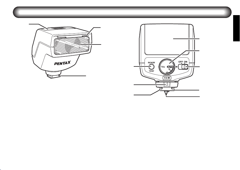
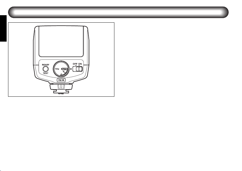
各部の名称
電池ぶた
ワイドパネル板
発光部
シューブラケット
テストボタン/充電完了ランプ
締め付けノブ
モードダイヤル
電源スイッチ
シューロックピン
ストロボ信号接点
(奥のピン)
5
Page 8
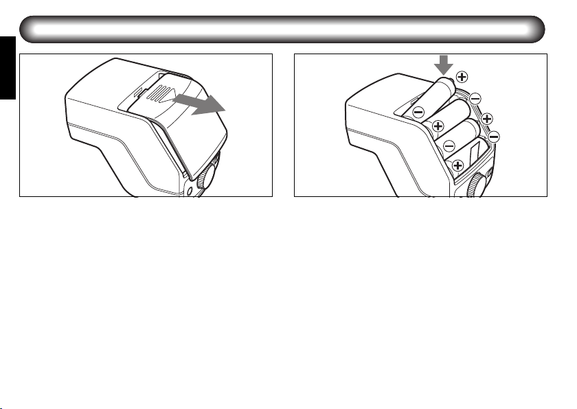
電池の入れ方
1
図のように電池ぶたをスライドしてか
1
ら、電池ぶたを外します。
6
2
4本の単3形電池を電池室内の+-に合わ
2
せて下から順に入れ、電池ぶたを元のよ
うに閉じます。
● 電池を入れる際に、電池室内のリボンを電池の
下に通しておくと、電池を取り出すときにリボ
ンの先端を引っ張ることで簡単に外すことが
できます。
Page 9

■ 電池の種類
電池は、次の種類の単3形電池で同一種類のも
のを4本使用します。
単3形アルカリ電池(LR6)
単3形リチウム電池(FR6)
単3形ニッケル水素電池(Ni-MH)
(ニッケルマンガン電池とニッカド電池(Ni-
cd)は使用できません)
● 発光間隔と発光回数については、主な仕様(20
ページ)を参照してください。
● 電源を入れても(8ページ)充電完了ランプが
点灯しないときは、電池が正しく入っていない
か、消耗しています。電池の向きを確認し、そ
れでも点灯しなければ、新品電池に交換してく
ださい。
● 充電に 20 秒以上かかるときは電池が消耗して
いますので、新しい電池と交換してください。
● リチウム電池(FR6)で、ストロボを連続して
発光させると、電池の発熱により電池の安全回
路が働き、一時的にご使用いただけなくなるこ
とがあります。この場合、しばらく休ませて電
池の温度を下げると、問題なく使用できるよう
になります。
7
Page 10
電源の入れ方
8
電源スイッチを(ON)の位置に合わせると電
源が入ります。充電完了ランプが点灯すれば
充電完了です。(OFF)の位置に合わせると電
源が切れます。
テスト発光
充電完了後、テストボタン(TEST)を押すと
テスト発光ができます。
オートパワーオフ機能
オートパワーオフは、電源スイッチを(ON)
にした状態で、約3分間放置すると自動的に電
源が切れる節電機能です。
クイックスタート機能
ストロボがオートフォーカスカメラに取り付
けられている場合は、シャッターボタンを半
押しすると電源が入ります。
Page 11
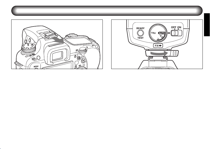
カメラへの取り付け方
1
カメラのホットシューカバーを外しま
1
す。
ストロボをカメラに取り付けます。
2
ストロボの締め付けノブを「FIX→」と
反対方向へ回します。
ストロボのシューブラケットをカメラの
ホットシューに後方から差し込みます。
ストロボの締め付けノブを「FIX→」の
方向に回して固定します。
2
● ペンタックスデジタル一眼レフカメラは、
シューロックピンに対応しています。取り付
けるときは、締め付けノブを「FIX →」方向
に回して、シューロックピンでストロボを固
定してください。取り外すときは、必ず締め
付けノブを「FIX→」と反対の方向に回して、
ノブを緩めてから取り外してください。固定
したままの取り外しは、ホットシューが傷つ
く原因となります。
9
Page 12
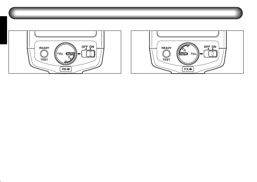
オートストロボAF200FGのモードダイヤルについて
AF200FGの背面にある、モードダイヤルで発光モードを設定します。
オートストロボモード(P-TTL・TTLオート)
ストロボのモードダイヤルを「AUTO」「–0.5」
「–1」のいずれかに設定します。使用するカメ
ラ側と通信することによりオートストロボの
動作がP-TTL オートまたはTTL オートに自動
的に切り替わります。
P-TTLオート
撮影の直前にプリ発光を行い、被写体の状態をカメ
ラ側のセンサーで測定して、撮影時の発光量を調整
しますので、通常のTTLモードより更に正確な露出
調整が可能です。
TTLオート
レンズを通ってきた撮影中の光をカメラのセン
サーで測定して、ストロボの発光量を調整します。
10
マニュアルストロボモード(フル発光)
ストロボのモードダイヤルを「FULL」に設定
します。周囲の明るさに関係なく、常にフル
発光します。
使用するカメラ側のISO 感度設定からストロ
ボのガイドナンバー(GN)を出し、発光距離
より、絞りを算出して撮影しますので、絞り
を任意に設定できるすべてのカメラで使用可
能です。
Page 13
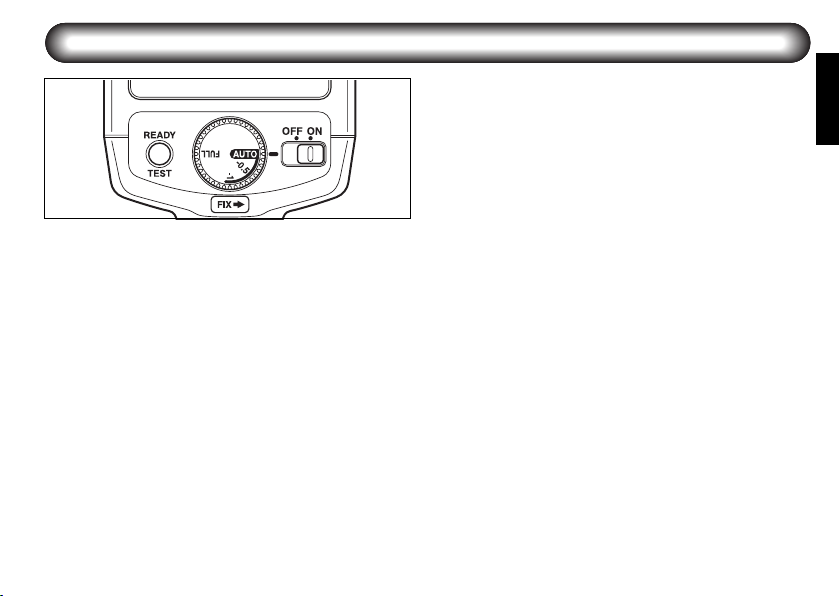
オートストロボ撮影
撮影手順
ストロボの電源スイッチを(ON)にしま
1
す
AUTO
ストロボのモードダイヤルを(
2
します
撮影可能距離と充電完了を確認して、撮
3
影します
● オートフォーカスレンズ以外では P-TTL オー
トは正確な調光ができません。
)に
P-TTLオートストロボで使うには レンズの絞
りをA位置に
DA
レンズや
お使いのレンズに絞りリングがある場合は、絞
りA位置にしてご使用ください。そうしない
P-TTL
と、
P-TTL
*ist DS2,*ist DS,*ist D
(
の絞り位置がA 以外でも
として撮影できますが、
カメラでは、絞りがA以外になると、調光がで
きなくなり、ストロボはフル発光となりますの
で、ご注意ください。
TTLオートストロボモードについて
ペンタックスデジタル一眼レフシリーズ以外
の従来機(フィルム一眼レフカメラ)でも、
オートストロボ対応機であれば、同様にオート
ストロボ撮影が可能です。(ただし、SFシリー
ズ以前および初期型の
ておりません)
FAJ
レンズでは問題ありませんが、
オートストロボとして作動しません。
モードと
TTL
モードに両対応のカメラ
)であれば、レンズ
TTL
オートストロボ
P-TTL
ストロボ専用の
645
カメラには、対応し
TTL
11
Page 14

■ P-TTLオート調光範囲目安表
ISO
照射角
感度
標準
ISO
ワイド
100
パネル
標準
ISO
ワイド
200
パネル
標準
ISO
ワイド
400
パネル
標準
ISO
ワイド
800
パネル
標準
ISO
ワイド
1600
パネル
※ ストロボのモードダイヤルが「AUTO」のとき、カメラ側のISO感度とレンズの絞り値の組み合わせで、調光可能な距離範囲(適正露出で
撮影できる距離)目安がわかります。(「ワイドパネル」行はワイドパネル使用時の値)
1.4 2 2.8 4 5.6 8 11 16 22
2.1~14.3 1.5~10.0 1.1~7.1 0.7~ 5.0 0.7~3.6 0.7~2.5 0.7~1.8 0.7~1.3 0.7~0.9
1.6~10.7 1.1~ 7.5 0.8~ 5.4 0.7~ 3.8 0.7~ 2.7 0.7~ 1.9 0.7~ 1.4 0.7~ 0.9 0.7~ 0.7
3.0~20.0 2.1~14.0 1.5~10.0 1.0~7.0 0.7~ 5.0 0.7~3.5 0.7~2.5 0.7~ 1.8 0.7~1.3
2.2~15.0 1.6~10.5 1.1~ 7.5 0.8~ 5.3 0.7~ 3.8 0.7~ 2.6 0.7~ 1.9 0.7~ 1.3 0.7~ 1.0
4.2~28.6 3.0~20.0 2.1~14.3 1.5~10.0 1.1~ 7.1 0.7~ 5.0 0.7~ 3.6 0.7~2.5 0.7~1.8
3.2~21.4 2.2~15.0 1.6~10.7 1.1~ 7.5 0.8~ 5.4 0.7~ 3.8 0.7~ 2.7 0.7~ 1.9 0.7~ 1.4
6.1~40.7 4.2~28.5 3.0~20.4 2.1~14.3 1.5~10.2 1.1~ 7.1 0.8~ 5.2 0.7~3.6 0.7~2.6
4.5~30.0 3.1~21.0 2.2~15.0 1.6~10.5 1.1~ 7.5 0.8~ 5.3 0.7~ 3.8 0.7~ 2.6 0.7~ 1.9
8.5~57.1 5.9~40.0 4.2~28.6 3.0~20.0 2.1~14.3 1.5~10.0 1.1~ 7.3 0.7~5.0 0.7~3.6
6.4~42.9 4.5~30.0 3.2~21.4 2.2~15.0 1.6~10.7 1.1~ 7.5 0.8~ 5.5 0.7~ 3.8 0.7~ 2.7
12
絞り値(F値)
(単位:m)
Page 15
マニュアルストロボ撮影
撮影手順
電源スイッチを(ON)にします
1
ストロボのモードダイヤルを(FULL)に
2
合わせます
撮影距離(ストロボの発光距離)を測り、
3
次の計算で使用する絞り値を求めます。
(ガイドナンバーはISO感度によって変わ
ります。14 ページの表を参照してくださ
い)
例:撮影距離=2.5m、ISO 感度=100、ワイ
ドパネル板を使用しない場合
ガイドナンバーは20。
絞り値= =8
4
5
ガイドナンバー 20
撮影距離 2.5m
求めた絞り値をセットします
充電完了を確認して、撮影します。
13
Page 16

■ マニュアルストロボ距離目安表
ISO
100
200
400
800
1600
3200
※ ストロボのモードダイヤルが「FULL」のとき、カメラ側のISO感度とレンズの絞り値の組み合わせで、適正撮影距離(光が届く距離)が
求められます。(「ワイドパネル」行はワイドパネル使用時の値)
照射角
標準
ワイドパネル
標準
ワイドパネル
標準
ワイドパネル
標準
ワイドパネル
標準
ワイドパネル
標準
ワイドパネル
GN
1.4 2 2.8 4 5.6 8 11 16 22
20 14.3 10.0 7.1 5.0 3.6 2.5 1.8 1.3 0.9
15 10.7 7.5 5.4 3.8 2.7 1.9 1.4 0.9 0.7
28 20.0 14.0 10.0 7.0 5.0 3.5 2.5 1.8 1.3
21 15.0 10.5 7.5 5.3 3.8 2.6 1.9 1.3 1.0
40 28.6 20.0 14.3 10.0 7.1 5.0 3.6 2.5 1.8
30 21.4 15.0 10.7 7.5 5.4 3.8 2.7 1.9 1.4
57 40.7 28.5 20.4 14.3 10.2 7.1 5.2 3.6 2.6
42 30.0 21.0 15.0 10.5 7.5 5.3 3.8 2.6 1.9
80 57.1 40.0 28.6 20.0 14.3 10.0 7.3 5.0 3.6
60 42.9 30.0 21.4 15.0 10.7 7.5 5.5 3.8 2.7
113 80.7 56.5 40.4 28.3 20.2 14.1 10.3 7.1 5.1
85 60.7 42.5 30.4 21.3 15.2 10.6 7.7 5.3 3.9
絞り値(F値)
(単位:m)
14
Page 17
ストロボの応用撮影
■ 低速シンクロ撮影
夜景や夕景をバックに、手前の人物などをき
れいに写しこみたいとき、普通にストロボ撮
影をすると、背景にストロボの光が届かない
ので、バックが真っ暗な写真になりがちです。
そのような場合、シャッター速度を遅くして、
背景に露出を合わせた上でオートストロボ撮
影をすると、背景と人物をバランスよく写し
込むことができます。
カメラが対応していればオートストロボ撮影
が可能です。撮影時には、次のことを確認し
てください。
1 お使いのカメラは、低速シンクロ撮影に対応し
ていますか?
2 お使いのカメラの撮影モードは、低速シンクロ
撮影に対応していますか?
● カメラの使用説明書もご覧ください。
カメラの種類
K200D、K100D/
-super、*ist DS/DS2、
*ist DL/DL2
K20D、K10D
*ist D
低速シンクロモード
非対応撮影モード
AUTO PICT
P(プログラム)、SCN(*ist DL2)、
Av(絞り優先)
グリーンモード カメラがP(ハイパープログラム)、AV(絞り優
グリーンモード、
、Av(絞り優先)
グラム)
P(ハイパープロ
、
では、最長1秒までの低速シンクロ撮影が可
能です。
先)、SV(感度優先)の場合は、カメラのストロボ
発光モードをスローシンクロに設定してください。
カメラが
ヤルまたは
秒以下にできれば、低速シンクロ撮影が可能です。
P
(ハイパープログラム)でも、Avダイ
Tv
ダイヤルで、シャッター速度を
・カメラのシャッター速度は、必ず同調速度より低速に設定してください。
備考
1/150
15
Page 18

■ ストロボの発光量を補正する
P-TTL オートストロボ撮影時に、ストロボの
モードダイヤルでストロボの光量を補正する
ことができます。
※ カメラ側でストロボ光量補正ができる機種
の場合、ストロボ側とカメラ側の両方で補
正値を設定すると、補正量は合算されます。
(カメラの説明書もご覧ください)
AUTO: 通常発光となります(ストロボ側
補正なし)
– 0.5:
– 1:1EV分ストロボの発光量が少な
16
0.5EV分ストロボの発光量が少な
くなります
くなります
Page 19

■ ワイドパネル板を使用する
AF200FG には、ワイドパネル板が内蔵されて
いますので、図のように、ワイドパネル板を
引き出して使用します。
ワイドパネル板を使用すると、ストロボの光
が拡散して、より広い範囲(広角レンズを使
用して)の撮影が可能になります。
ただし、光が拡散する分、光の届く距離は短
くなりますから、必要のないときは、収納し
ておいてください。
17
Page 20

■
AF200FG
を延長コードでつないで使用する
別売のストロボアクセサリーを組み合わせて
使用すると、ストロボをカメラから離しての
オート撮影をすることができます。
被写体の側面から光を当てて、影を作り出し
たり、背景までストロボの光を回り込ませた
り、カメラの内蔵ストロボと組み合わせて
様々なストロボ撮影を楽しむことができます
カメラから離した AF200FG を、コードでつな
いで使う場合は、延長コードF5P(別売)を使
用します。カメラ側は、ホットシューアダプ
ター F
(別売)またはホットシューアダプ
G
ター F(別売)を使用し、ストロボ側はオフカ
メラシューアダプター F を使って接続してく
ださい。(図参照)
● カメラの内蔵ストロボとAF200FG を組み合わ
せて使う場合は、ホットシューアダプター F
を使用してください。ホットシューアダプター
F を使用すると、内蔵ストロボが上がりきら
ず、使用できません。
18
●
ストロボをカメラから離して設置するとき、三
脚などを使用する場合はオフカメラシューアダ
F
プター
設置する場合はオフカメラシュークリップ
10
● K20D など、カメラ側で後幕シンクロ設定をし
ても、AF200FGを使用すると無効になります。
を、テーブルや椅子など任意の場所に
を使用してください。
延長コード F5P
ホットシュー
アダプター F
G
CL-
G
Page 21

別売アクセサリー
オフカメラシュークリップCL-10
AF200FG などをカメラから離して使用すると
きのセッティング用クリップ。
ホットシューアダプター F
G
延長コードF5P を用いてストロボをカメラと
離して使用するためのアダプター。内蔵スト
ロボとの併用も可能です。
オフカメラシューアダプター F
外付けストロボなどをカメラから離して三脚
に固定するためのアダプター。延長コードF5P
用のコネクターを備えています。
ホットシューアダプター F
カメラのホットシューに装着し、延長コード
F5P 用のシンクロ接点を追加するアダプター。
上部にホットシューを持っています。
延長コードF5P - 0.5m/1.5m/L(約3m)
AF540FGZ、AF360FGZ、AF200FGなどのオー
トフォーカス一眼レフ用ストロボをカメラか
ら離して使用するための5P シンクロコード。
ホットシューアダプター F
・F、オフカメラ
G
シューアダプター F と併用します。
ホットシューグリップ67 2
AF540FGZ、AF360FGZ、AF200FG などのク
リップオンタイプのストロボを67 Ⅱに取り付
けるためのグリップ。付属の 5P シンクロコー
ドで67 Ⅱに接続します。
19
Page 22

主な仕様
型式 クリップオン式直列制御TTLオートストロボ
オート撮影対応カメラ デジタル一眼レフカメラシリーズ
ガイドナンバー 最大20(ISO100/m)
発光間隔/発光回数
照射角度 上下26.5°、左右35°(ワイドパネル使用時:上下30°、左右39°)
光質 昼光色(デーライトカラーフィルムに適合)
20
Zシリーズ以降の35 ミリ( フィルム) オートフォーカス一眼レフカメラ
645N・645NIIおよび 67II カメラ
Format
ISO
100 (FULL) 20 15
200 (FULL) 28 21
400 (FULL) 40 30
800 (FULL) 57 42
1600 (FULL) 80 60
3200 (FULL) 113 85
アルカリ電池(LR6)約4秒約300回
ニッケル水素電池
(Ni-MH/2700mAh)
リチウム電池(FR6)約4秒約450回
35mm 28mm 24mm
645 55mm 45mm
67 70mm 60mm
DIGITAL 19mm 16mm
電池の種類 発光間隔 発光回数
標準 ワイドパネル
約4秒約400回
Page 23

オート連動範囲 約0.7m~約 3.6m(ガイドナンバー 20、ISO100、絞りF5.6のとき)
ISO感度連動範囲 ISO 100~1600(P-TTL 時)
ストロボ発光モード P-TTLオート、TTLオート、マニュアル(FULL)
光量補正 –0.5EV、–1EV モードダイヤル切り替えによる
節電機能 電源オートオフ
赤目軽減発光機能 赤目軽減機能付オートフォーカスカメラに連動
ワイドパネル 引き出し式
電源
大きさ・重さ (幅)68 ×(高)83.5 ×(厚)93(mm) 約190 g(電池別)
単3形電池4本(アルカリ電池(
LR6
)、ニッケル水素電池(
Ni-MH
)、リチウム電池(
FR6
))
21
Page 24

付録
ストロボオート撮影時の機能対応表
カメラタイプ
ストロボモード
先幕シンクロ ○×○○
後幕シンクロ ××××
ハイスピードシンクロ ××××
スローシンクロ ○×○○
同調速度自動切換え ○○○○
ファインダー内充電完了表示○○○○
ファインダー内オートチェック×××○
赤目軽減 ○○○○
ストロボのモードダイヤルによ
る発光量補正
○:使用できます
×:使用できません
※
*ist DS2、*ist DS、*ist D
TTL
オートに切り替わります。
AF200FG
※
使用時は、
カメラでは、レンズの絞りを A以外にセットすると、ストロボの動作モードが
K20D、K10D、K200D
22
K20D、K10D、K200D、
K100D/-super、*ist DL2、*ist DL
P-TTLオート
動作時
TTLオート
動作時
*ist DS2、*ist DS、*ist D
P-TTLオート
動作時
TTLオート
動作時
○×○×
P-TTL
オートから、
カメラ側での後幕シンクロ設定は、無効になります。
Page 25

MEMO
23
Page 26

アフターサービスについて
1. 本製品が万一故障した場合は、ご購入日から満1 年間
無料修理致しますので、お買い上げ店か当社お客様
窓口にお申し出ください。修理をお急ぎの場合は、
当社お客様窓口に直接お持ちください。修理品ご送
付の場合は、化粧箱などを利用して、輸送中の衝撃
に耐えるようしっかりと梱包してお送りください。
不良見本のサンプルや故障内容の正確なメモを添付
していただけると原因分析に役立ちます。
2. 保証期間中(ご購入後1 年間)は、保証書(販売店印
および購入年月日が記入されているもの)をご提示
ください。保証書がないと保証期間中でも修理が有
料になります。なお、販売店または当社お客様窓口
へお届けいただく諸費用はお客様にご負担願いま
す。また、販売店と当社間の運賃諸掛りにつきまし
ても、輸送方法によっては一部ご負担いただく場合
があります。
3. 次の場合は、保証期間中でも無料修理の対象にはな
りません。
• 使用上の誤り(使用説明書記載以外の誤操作等)に
より生じた故障。
• 当社の指定するサービス機関以外で行われた修
理・改造・分解による故障。
• 火災・天災・地変等による故障。
24
• 保管上の不備(高温多湿の場所、防虫剤や有害薬
品のある場所での保管等)や手入れの不備(本体
内部に砂・ホコリ・液体かぶり等)による故障。
• 修理ご依頼の際に保証書のご提示、添付がない場
合。
• お買い上げ販売店名や購入日等の記載がない場合
ならびに記載事項を訂正された場合。
4. 保証期間以降の修理は有料修理とさせていただきま
す。なお、その際の運賃諸掛りにつきましてもお客
様のご負担とさせていただきます。
5. 本製品の補修用性能部品は、製造打ち切り後5 年間を
目安に保有しております。したがって本期間中は原
則として修理をお受け致します。なお、期間以後で
あっても修理可能の場合もありますので、当社お客
様窓口にお問い合わせください。
6. 海外でご使用になる場合は、国際保証書をお持ちく
ださい。国際保証書は、お持ちの保証書と交換に発
行いたしますので、当社のお客様窓口にご持参また
はご送付ください。(保証期間中のみ有効)
7. 保証内容に関して、詳しくは保証書をご覧ください。
Page 27

■ ペンタックスピックアップリペアサービス
全国(離島など、一部の地域を除く)どこからでも電話一本でペンタックス指定の宅配業者がお
客様ご指定の日時・場所に梱包資材を持って不具合品を引き取りにお伺いし、専門修理スタッフ
が修理を行なって、お客様ご指定の場所に完成品をお届けするサービスです。
電話受付
TEL 0120-97-0405 (フリーダイヤル)
(受付時間 :平日8:00-21:00 土・日・祝日・年末年始9:00-18:00)
(宅配便・郵便による修理受付、修理に関するお問い合わせ)
ペンタックス イメージング・システム事業部
東京サービスセンター 03-3975-4341(代)
〒175-0082 東京都板橋区高島平6-6-2 ペンタックス流通センター内
営業時間:午前9:00~午後5:00(土・日・祝日および弊社休業日を除く)
ペンタックス イメージング・システム事業部
大阪サービスセンター 06-6271-7996(代)
〒542-0081 大阪市中央区南船場1-17-9 パールビル2階
営業時間:午前9:00~午後5:00(土・日・祝日および弊社休業日を除く)
25
Page 28

お客様窓口のご案内
[弊社製品に関するお問い合わせ]
お客様相談センター
(市内通話料でご利用いただけます。)
ナビダイヤル 0570-001313
携帯電話、
ださい。
03-3960 -3200
〒
営業時間 午前 9:
PHS
およびIP電話の方は、下記の電話番号をご利用く
174-8639
(代)
東京都板橋区前野町
00
(土・日・祝日および弊社休業日を除く)
~午後 6:
2-36-9
00
HOYA株式会社
ペンタックス イメージング・システム事業部
〒174-8639 東京都板橋区前野町 2-36-9
☆仕様および外観の一部を予告なく変更することがあります。
Page 29

ELECTRONIC
FLASH UNIT
OPERATING MANUAL
EN
Page 30

FOR THE SAFE USE OF YOUR FLASH UNIT
Although we have carefully produced this flash unit for safe operation, please be sure to especially follow warnings
and cautions given on page 1.
WARNING
This symbol indicates that violating this item could cause serious personal injuries.
CAUTION
This symbol indicates that violating this item could cause minor or medium personal injuries, or material losses.
is a symbol indicating items that are prohibited.
is a symbol emphasizing a warning.
Page 31

WARNING
The flash contains electronic circuits that
operate at high voltages. Do not attempt to
disassemble the flash unit yourself, as there is
danger of an electric shock.
If internal parts of the flash unit becomes
exposed due to impact, etc., do not touch them
as there is danger of an electric shock.
Do not expose the flash unit to water or
moisture as there is danger of an electric
shock.
CAUTION
Do not use the flash near anyone’s eyes, as it
may hurt them. Be particularly careful with the
flash around infants.
The following may lead to an explosion or fire.
● Shorting the batteries
● Exposing the batteries to flames
● Dismantling the batteries
● Attempting to recharge non-rechargeable
batteries
Remove the batteries from the camera
immediately if they become hot or begin to
smoke. Be careful not to burn yourself during
removal.
1
Page 32

Precautions for Your Flash Unit
● Never use organic solvents such as paint thinner, alcohol or benzene to clean the flash unit.
● Avoid leaving the flash unit for extended period in places where the humidity and temperature are very high
such as in a car.
● Be careful not to subject the flash unit to strong vibrations, shock or pressure. Use a cushion to protect the flash
unit when carrying it in a motorcycle, car, boat, etc.
● Do not use the flash unit where it may be directly exposed to rain, water, etc.
● Replace all the batteries at the same time. Do not mix battery brands, type or an old battery with a new one. It
may cause explosion or overheating.
● When using the flash unit off the camera, do not try to attach any metallic object to the electric contacts or to
mount incompatible accessories. Otherwise, the TTL auto mechanism may be damaged or rendered
inoperable.
● Do not attach any accessories having either fewer or different (layout other than PENTAX standard) electrical
contacts for the hot shoe or grip. Otherwise, some functions may not work properly.
● PENTAX will not be held responsible for any accidents or damage, etc. caused due to the use of this product
with cameras and accessories made by companies other than PENTAX.
● Periodic checks are recommended every 1 to 2 years in order to maintain high performance. If the unit has not
been used for an extended period of time, or is being readied for an important shoot, it is recommended that
you take a test flash with the test button and test shoot with it. Test flash is also important to maintain optimum
performance.
● Avoid contact with garbage, dirt, sand, dust, water, toxic gases, salt, etc. When the flash unit is subjected to rain
or moisture, wipe it off with a dry soft cloth.
2
Page 33

● Remove the batteries when not using the flash unit for extended periods. Otherwise, battery leakage might
result and cause damage to the circuitry and proper operation of the flash unit.
● Battery performance may temporarily be hindered in low temperatures. Batteries should be kept warm in
temperatures below freezing for proper performance.
● When photographing black subjects or white subjects, use exposure compensation.
3
Page 34

Contents
FOR THE SAFE USE OF YOUR FLASH UNIT
Precautions for Your Flash Unit ....................... 2
Names of Parts ................................................... 5
Inserting the Batteries ....................................... 6
Types of Batteries............................................... 7
Turning the Power On........................................ 8
Mounting to Camera .......................................... 9
Mode Dial Functions ........................................ 10
Auto flash shooting ......................................... 11
Approximate effective flash range in P-TTL
Auto flash...................................................... 12
Manual flash shooting ..................................... 13
Approximate flash distance in Manual flash...... 14
4
Application Shooting of Auto Flash ............... 15
Slow-speed Sync Mode .................................... 15
Compensating Flash Output ............................. 16
Using the Wide-angle Panel ............................. 17
Connecting the AF200FG with the Extension
Cord .............................................................. 18
Optional Accessories ...................................... 19
Specifications................................................... 20
Appendix........................................................... 22
Table of dedicated functions at Auto
flash shooting................................................ 22
Warranty Policy ................................................ 23
Page 35

Names of Parts
Battery chamber cover
Wide-angle panel
Flash head
Shoe foot
Test button/ Ready lamp
Locking lever
Mode dial
Power switch
Shoe lock pin
Flash signal contacts
(Inner pin)
5
Page 36

Inserting the Batteries
1
Slide the battery chamber cover as shown in the
1
figure and remove it.
6
2
Insert the above four AA batteries sequentially
2
from lower one making sure the plus/minus
markings +, - match the diagram inside the
battery chamber and close the battery chamber
cover.
● If you thread the ribbon in the battery chamber
under the batteries beforehand when inserting
the batteries, you can remove the batteries easily
by pulling the ribbon when removing the
batteries.
Page 37

■Types of Batteries
This flash unit uses four AA batteries of the same type,
as shown below.
Alkaline battery (LR6)
Lithium battery (FR6)
Nickel-Metal Hydride battery (Ni-MH)
(Nickel manganese (Ni-Mn) and nickel cadmium
(Ni-Cd) batteries cannot be used.)
● For information about recycling times and total
number of flashes, refer to “Specifications” on
page 20.
● If the ready lamp does not light up when you turn
on the power (page 8), the batteries may be
exhausted or not inserted correctly. Verify the
orientation of the batteries or, if the indicators
and ready lamp still do not light up, replace them
with new batteries.
● If charging time takes more than 20 seconds, the
batteries are exhausted and should be replaced
with new batteries.
● If you let the flash unit discharge successively
using lithium batteries, the batteries will overheat,
activating a safety circuit that temporarily
disables the flash unit. If this occurs, rest the
flash unit so that the temperature of the batteries
returns to normal.
7
Page 38

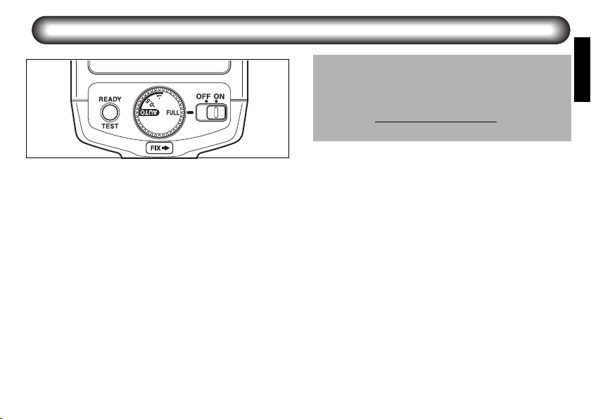
Turning the Power On
8
Sliding the power switch to the (ON) position will turn
on the power. The ready lamp will light up when the
flash is charged. Sliding it to the (OFF) position will turn
off the power.
Test Flash
Check that the ready lamp is lit, then press the test
button (TEST). The test flash will discharge.
Auto Power Off Function
When the flash unit is left unused for about 3 minutes
with the power switch set to the (ON) position, it
automatically turns off to save the power.
Quick Start Function
If the flash unit is mounted on autofocus cameras,
press the shutter release button half way to turn on the
power.
Page 39

Mounting to Camera
1
Remove the hot shoe cover from the camera.
1
Attach the flash unit to the camera.
2
Turn the locking lever of the flash unit in the
direction opposite to that indicated by (FIX➝).
Slide the hot shoe foot of the flash unit into the
camera's hot shoe from the back of the
camera forward.
Turn the locking lever of the flash unit in the
direction indicated by (FIX➝) to lock it.
2
●
PENTAX digital single lens reflex cameras can
accept a shoe lock pin. When attaching the flash
unit, turn the locking lever in the (FIX➝) direction
and lock the flash unit to the camera with the shoe
lock pin. When releasing the flash unit, be sure to
do so after turning the locking lever in the
direction opposite to that indicated by (FIX➝) and
loosening the shoe lock pin. Otherwise, the hot
shoe will be damaged.
9
Page 40

Mode Dial Functions
Using the mode dial located on the rear side of the AF200FG, you can set the following flash modes.
Auto flash mode (P-TTL Auto/ TTL Auto)
When the mode dial is set to (AUTO), (–0.5), or (–1),
the operating mode of the flash unit is automatically
switched to P-TTL Auto or TTL Auto by communicating
with the camera you use.
P-TTL Auto flash
A pre-flash is discharged before the main flash so that the
metering sensor in the camera can measure the condition
of the subject and adjust the output of the main flash
properly. This mode gives more accurate results than the
conventional TTL mode.
TTL Auto flash
The metering sensor in the camera measures the amount
of light coming through the lens and adjusts the flash
output properly.
10
Manual flash mode (full output)
When the mode dial is set to (FULL), the flash unit
always discharges at its full output regardless of the
ambient light condition.
Determine the Guide No. of the flash unit based on the
ISO sensitivity setting of the camera, then calculate the
aperture value according to the flash range.
This mode is available on all the cameras for which you
can set the desired aperture.
Page 41

Auto flash shooting
Procedure
Slide the Power switch to (ON).
1
Set the mode dial to (AUTO).
2
Confirm that the subject is within the effective
3
flash range and the ready lamp is lit, and take a
picture.
● The correct flash output is obtained in P-TTL
auto mode only when the flash unit is used with
auto-focus lenses.
Set the lens aperture to the position A in PTTL Auto mode
When the lens you use is equipped with the lens
aperture ring, set the position of the ring to A (You do
not need to do this for the DA or FAJ lens). Otherwise,
the flash unit cannot function in P-TTL Auto mode.
When you use the cameras that support both P-TTL
and TTL modes (*ist DS2, *ist DS, *ist D) , if the
aperture of the lens is in a position other than A, you can
shoot in TTL Auto flash mode. Be aware that for the
cameras that only support P-TTL Auto flash, the flash
unit does not adjust the flash output but discharges at
full output, if the aperture of the lens is in a position
other than A.
About TTL Auto flash mode
With single lens reflex cameras (film cameras) other
than PENTAX digital single lens reflex cameras, you
can perform auto flash shooting if they support TTL
Auto. (However, the 645 format cameras before SF
series and of the early type do not support the TTL
Auto)
11
Page 42

■ Approximate effective flash range in P-TTL Auto flash
sitivity
Flash
Coverage
Angle
1.422.845.68 111622
ISO sen-
Normal 2.1-14.3 1.5-10.0 1.1-7.1 0.7-5.0 0.7-3.6 0.7-2.5 0.7-1.8 0.7-1.3 0.7-0.9
ISO 100
With the wideangle panel
1.6-10.7 1.1-7.5 0.8-5.4 0.7-3.8 0.7-2.7 0.7-1.9 0.7-1.4 0.7-0.9 0.7-0.7
Normal 3.0-20.0 2.1-14.0 1.5-10.0 1.0-7.0 0.7-5.0 0.7-3.5 0.7-2.5 0.7-1.8 0.7-1.3
ISO 200
With the wideangle panel
2.2-15.0 1.6-10.5 1.1-7.5 0.8-5.3 0.7-3.8 0.7-2.6 0.7-1.9 0.7-1.3 0.7-1.0
Normal 4.2-28.6 3.0-20.0 2.1-14.3 1.5-10.0 1.1- 7.1 0.7-5.0 0.7-3.6 0.7-2.5 0.7-1.8
ISO 400
With the wideangle panel
3.2-21.4 2.2-15.0 1.6-10.7 1.1- 7.5 0.8- 5.4 0.7- 3.8 0.7- 2.7 0.7- 1.9 0.7- 1.4
Normal 6.1-40.7 4.2-28.5 3.0-20.4 2.1-14.3 1.5-10.2 1.1- 7.1 0.8- 5.2 0.7-3.6 0.7-2.6
ISO 800
* You can check the approximate range of distances within which the flash unit can adjust the flash output (and the appropriate exposure is
With the wideangle panel
Normal 8.5-57.1 5.9-40.0 4.2-28.6 3.0-20.0 2.1-14.3 1.5-10.0 1.1- 7.3 0.7-5.0 0.7-3.6
ISO
With the wide-
1600
angle panel
available) based on the combination of the ISO sensitivity setting on the camera and the aperture value from the above table when the mode
dial is set to (AUTO). (The values in "Wide Panel" line indicate the range when the wide-angle panel is used.) Note that the minimum range
that will give correct exposure is 0.7 meters.
4.5-30.0 3.1-21.0 2.2-15.0 1.6-10.5 1.1- 7.5 0.8- 5.3 0.7- 3.8 0.7- 2.6 0.7- 1.9
6.4-42.9 4.5-30.0 3.2-21.4 2.2-15.0 1.6-10.7 1.1- 7.5 0.8- 5.5 0.7- 3.8 0.7- 2.7
12
Aperture (F value)
(Unit: m)
Page 43

Manual flash shooting
Procedure
Slide the Power switch to (ON).
1
Set the mode dial to (FULL).
2
Measure the distance to the subject (between the
3
AF200FG and subject) and determine the
aperture value using the following procedure.
(The Guide No. varies depending on the ISO
sensitivity. Refer to the table on page 14.)
Example: If the subject distance (between the
The Guide No. will be 20.
Aperture = = 8
4
5
AF200FG and subject) is 2.5 m,
sensitivity is ISO 100, and the wide-angle
panel is not in use, the calculation will
become as follows:
Guide No.
Subject distance202.5
Set the lens aperture to the calculated value.
Confirm that the ready lamp is lit. Then take a
picture.
13
Page 44

■ Approximate flash distance in Manual flash
Flash
ISO
sensitivity
Coverage
Angle
GN
1.4 2 2.8 4 5.6 8 11 16 22
Normal 20 14.3 10.0 7.1 5.0 3.6 2.5 1.8 1.3 0.9
100
With the wideangle panel
15 10.7 7.5 5.4 3.8 2.7 1.9 1.4 0.9 0.7
Normal 28 20.0 14.0 10.0 7.0 5.0 3.5 2.5 1.8 1.3
200
With the wideangle panel
21 15.0 10.5 7.5 5.3 3.8 2.6 1.9 1.3 1.0
Normal 40 28.6 20.0 14.3 10.0 7.1 5.0 3.6 2.5 1.8
400
With the wideangle panel
30 21.4 15.0 10.7 7.5 5.4 3.8 2.7 1.9 1.4
Normal 57 40.7 28.5 20.4 14.3 10.2 7.1 5.2 3.6 2.6
800
With the wideangle panel
42 30.0 21.0 15.0 10.5 7.5 5.3 3.8 2.6 1.9
Normal 80 57.1 40.0 28.6 20.0 14.3 10.0 7.3 5.0 3.6
1600
With the wideangle panel
60 42.9 30.0 21.4 15.0 10.7 7.5 5.5 3.8 2.7
Normal 113 80.7 56.5 40.4 28.3 20.2 14.1 10.3 7.1 5.1
3200
* The appropriate shooting distance (distance at which the appropriate exposure is available) is determined based on the combination of the
ISO sensitivity setting and the aperture value on the camera when the mode dial is set to (FULL). (The values in "Wide Panel" line indicate the
distance when the wide-angle panel is used.) Note that the minimum range that will give correct exposure is 0.7 meters.
With the wideangle panel
85 60.7 42.5 30.4 21.3 15.2 10.6 7.7 5.3 3.9
14
Aperture (F value)
(Unit: m)
Page 45

Application Shooting of Auto Flash
■ Slow-speed Sync Mode
When using a normal flash to shoot a portrait, etc., in a
night or evening setting, the background will appear
very dark because a normal flash light cannot
sufficiently light it. However, it is possible to balance
both subject and background by using the flash to
properly expose the foreground subject and a slow
shutter speed to expose the low light background.
If your camera supports this mode, you can perform
auto flash shooting. Before shooting, confirm the
following.
1. Whether your camera supports slow-speed sync
mode.
2. Whether the shooting mode of your camera
supports slow-speed sync mode.
● Also refer to the operation manual of the camera.
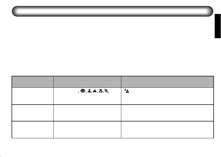
Camera Model
K200D, K100D/-super,
K110D,
*istDS/2, *istDL/2
K20D, K10D Green mode Set the flash mode of the camera to slow-
*ist D Green, P (Hyper Program) and Av
- Be sure to make the shutter speeds slower than the X-sync speed.
Shooting Modes Not Supported by
Slow-speed Sync Mode
AUTO PICT, , P
(Programmed AE), SCN (*ist DL2), Av
(Aperture priority) modes
(Aperture priority) modes
Notes
You can shoot in slow-speed sync mode for up
to one second in mode.
speed sync mode when the camera is in P
(Hyper Program) , Av (Aperture priority) or Sv
(Sensitivity priority) mode.
You can shoot in slow-speed sync mode when
the camera is in P (Hyper Program) mode if
you can set the shutter speed to 1/150 sec or
faster using the Av dial or Tv dial.
15
Page 46

■ Compensating Flash Output
When shooting in P-TTL auto flash mode, you can
compensate the flash output using the mode dial on the
flash unit.
If the camera also has the flash output compensation
*
function, and flash output compensation is set both
on the camera and the flash unit, the flash output
compensation amount will be combined.
Refer to the camera operation manual for details.
AUTO: Discharges at the normal
– 0.5: Reduces the flash output by
– 1: Reduces the flash output by
16
output (flash output
compensation is not set on the
flash unit)
0.5 EV.
1 EV.
Page 47

■Using the Wide-angle Panel
The AF200FG has a built-in wide-angle panel. Pull out
the wide-angle panel as shown in the figure.
The wide-angle panel disperses the flash light and
expands flash coverage angle for the wider angle
lenses.
As the wide-angle panel reduces the effective flash
range, do not use it when not necessary.
17
Page 48

■Connecting the AF200FG with the
Extension Cord
By combining the optional accessories with the flash
unit, you can perform auto flash shooting with the flash
unit held away from the camera.
You can enjoy various auto flash shooting features in
combination with the built-in flash, such as making
shadows by lighting a subject from the side, illuminating
the background, etc.
When you use the AF200FG held away from the
camera connected with an extension cord, use the
optional extension cord F5P/F5P L. Connect the
extension cord F5P/F5P L to the camera with the
optional hot shoe adapter F
adapter F, and connect it to the flash unit with the offcamenra shoe adapter F (refer to the diagram on the
right).
● When you use the AF200FG in combination with
the built-in flash unit of the cameras, attach the
hot shoe adapter F
adapter F, the built-in flash unit will not pop up
from the camera.
18
or the optional hot shoe
G
. If you use the hot shoe
G
● If you attach a tripod on the bottom of the camera
when setting up the flash unit held away from the
camera, use the off-camera shoe adapter F.
When you set up the camera on things such as a
tabletop or a chair, etc., use the optional offcamera shoe clip CL-10.
● If you set the camera such as the K20D, etc. to
trailing curtain sync mode, the setting becomes
invalid when you use the camera with the
AF200FG.
Extension cord F5P
Hot shoe
adapter F
G
Page 49

Optional Accessories
A number of dedicated accessories are available for
this flash unit.
Off-camera Shoe Clip CL-10
Setting clip for using the AF200FG held away from the
camera.
Hot Shoe Adapter F
Adapter for using the AF200FG as a separate flash unit
using the extension cord F5P/F5P L. It can be used in
combination with the built-in flash unit.
Off-camera shoe adapter F
Adapter for attaching an external flash unit, etc. on a
tripod separated from the camera. It comes with a
connector for the extension cord F5P/F5P L.
Hot Shoe Adapter F
Adapter for connecting the camera and extension cord
F5P/F5P L. It also has a hot shoe on its top.
G
Extension Cord F5P – 0.5m/1.5m/L
(Approx. 3m)
5P synchro cord to use a flash unit for single lens reflex
camera, such as the AF540FGZ, AF360FGZ or
AF200FG, held away from the camera. It is used in
combination with the hot shoe adapter FG or F, and/or
the off-camera shoe adapter F.
Hot Shoe Grip 67II
Adapter for positioning a flash unit such as the
AF540FGZ, AF360FGZ or AF200FG alongside the 67II
camera body. It connects to the 67II’s 5P sync terminal
with the included 5P Sync Cord.
19
Page 50

Specifications
Typ e Clip-on, TTL auto flash unit with series control
Cameras supporting the Auto
flash shooting • Digital SLR series
Guide No. Maximum 20 (ISO 100/m)
Recycling time/Total number of
flashes
20
• 35mm (Film) Autofocus SLR after Z series
• 645N, 645N II, and 67 II
Format
35mm 28mm 24mm
ISO
100 (FULL) 20 15
200 (FULL) 28 21
400 (FULL) 40 30
800 (FULL) 57 42
1600 (FULL) 80 60
3200 (FULL) 113 85
AA Nickel-Metal Hydride
645 55mm 45mm
67 70mm 60mm
DIGITAL 19mm 16mm
Battery type Recycling time Total number of flashes
AA Alkaline (LR6) Approx. 4 sec. Approx. 300
(Ni-MH/2700mAh)
AA Lithium (FR6) Approx. 4 sec. Approx. 450
Normal
With the wide-angle panel
Approx. 4 sec. Approx. 400
Page 51

Flash Coverage Angle
Color temperature
Effective flash range
ISO sensitivity setting
Flash modes
Flash output compensation
Power saving
Red-eye reduction
Wide-angle panel
Power source
Dimensions and weight
Vertical Angle: 26.5°, Horizontal Angle: 35°(When the wide-angle panel is used: Vertical
Angle: 30°, Horizontal Angle: 39°)
Daylight (Suited for daylight color film)
Approx. 0.7 m - approx. 3.6 m (Guide No. 20, ISO 100, f/5.6)
ISO 100 - 1600 (In P-TTL mode)
P-TTL auto, TTL auto, manual (FULL)
–0.5 or –1.0EV (switches with the mode dial)
Automatic power-off
Operates with auto-focus cameras equipped with red-eye reduction feature.
Pull out manually.
Four AA batteries, (Alkaline (LR6), Nickel-Metal Hydride (Ni-MH), or Lithium (FR6))
68 mm (W) × 83.5 mm (H) × 93 mm (T) (2.7'' × 3.3'' × 3.7''), Approx. 190 g (6.8 oz.)
without batteries
21
Page 52

Appendix
Table of dedicated functions at Auto flash shooting
Camera type
Flash Mode
Leading curtain sync
Trailing curtain sync
High-speed sync
Slow-speed sync
Automatic switching to X-sync
speed when flash is charged
Flash ready display in
viewfinder
Auto check display
Red-eye reduction
Flash output compensation
using the mode dial on the
flash unit
Yes: Available
No : Not available
* For the *ist DS2, *ist DS or *ist D camera, the flash mode is switched from P-TTL to TTL, if the aperture of the lens
is in a position other than A.
* The setting of trailing curtain sync mode on the K20D, K10D, K200D cameras becomes invalid when you use the
camera with the AF200FG.
22
K20D, K10D, K200D, K100D/-super,
K110D, *ist DL2, *ist DL
P-TTL auto
flash mode
Yes
No No No No
No No No No
Yes
Yes Ye s Yes Yes
Yes Ye s Yes Yes
No No No Yes
Yes Ye s Yes Yes
Yes N o Ye s N o
TTL auto
flash mode
No
No
*ist DS2, *ist DS, *ist D
P-TTL auto
flash mode
Yes Yes
Yes Yes
TTL auto
flash mode
Page 53

Warranty Policy
All PENTAX camera accessories purchased through authorized bona fide photographic distribution channels are guaranteed
against defects of material or workmanship for a period of twelve months from date of purchase. Service will be rendered,
and defective parts will be replaced without cost to you within that period, provided the equipment does not show evidence of
impact, sand or liquid damage, mishandling, tampering, battery or chemical corrosion, operation contrary to operating
instructions, or modification by an unauthorized repair shop. The manufacturer or its authorized representatives shall not be
liable for any repair or alterations except those made with its written consent and shall not be liable for damages from delay
or loss of use or from other indirect or consequential damages of any kind, whether caused by defective material or
workmanship or otherwise; and it is expressly agreed that the liability of the manufacturer or its representatives under all
guarantees or warranties, whether expressed or implied, is strictly limited to the replacement of parts as herein before
provided. No refunds will be made on repairs performed by non-authorized PENTAX service facilities.
Procedure During 12-month Warranty Period
Any PENTAX which proves defective during the 12-month warranty period should be returned to the dealer from whom you
purchased the equipment or to the manufacturer. If there is no representative of the manufacturer in your country, send the
equipment to the manufacturer, with postage prepaid. In this case, it will take a considerable length of time before the
equipment can be returned to you owing to the complicated customs procedures required. If the equipment is covered by
warranty, repairs will be made and parts replaced free of charge, and the equipment will be returned to you upon completion
of servicing. If the equipment is not covered by warranty, regular charges of the manufacturer or of its representatives will
apply. Shipping charges are to be borne by the owner. If your PENTAX was purchased outside of the country where you wish
to have it serviced during the warranty period, regular handling and servicing fees may be charged by the manufacturer’s
representatives in that country. Notwithstanding this, your PENTAX returned to the manufacturer will be serviced free of
charge according to this procedure and warranty policy.
In any case, however, shipping charges and customs clearance fees are to be borne by the sender. To prove the date of your
purchase when required, please keep the receipts or bills covering the purchase of your equipment for at least a year. Before
sending your equipment for servicing, please make sure that you are sending it to the manufacturer’s authorized
representatives or their approved repair shops, unless you are sending it directly to the manufacturer. Always obtain a
quotation for the service charge, and only after you accept the quoted service charge, instruct the service station to proceed
with the servicing.
23
Page 54

This warranty policy does not affect customer’s statutory rights.
The local warranty policies available from PENTAX distributors in some countries can supersede this warranty policy.
Therefore, we recommend that you review the warranty card supplied with your product at the time of purchase, or contact
the PENTAX distributor in your country for more information and to receive a copy of the warranty policy.
For customers in the USA
STATEMENT OF FCC COMPLIANCE
This device complies with Part 15 of the FCC Rules. Operation is subject to the following two conditions: (1) This device may
not cause harmful interference, and (2) this device must accept any interference received, including interference that may
cause undesired operation.
Changes or modifications not approved by the party responsible for compliance could void the user’s authority to operate the
equipment.
This equipment has been tested and found comply with the limits for a Class B digital device, pursuant to part 15 of the FCC
Rules. These limits are designed to provide reasonable protection against harmful interference in a residential installation.
This equipment generates, uses and can radiate frequency energy and, if not installed and used in accordance with the
instructions, may cause harmful interference to radio communications. However, there is no guarantee that interference will
not occur in a particular installation. If this equipment does not cause harmful interference to radio or television reception,
which can be determined by turning the equipment off and on, the user is encouraged to try to correct the interference by one
or more of the following measures:
• Reorient or relocate the receiving antenna.
• Increase the separation between the equipment and receiver.
• Consult the dealer or an experienced radio/TV technician for help.
For customers in Canada
This Class B digital apparatus complies with Canadian ICES-003.
Pour les utilisateurs an Canada
Cet appareil numérique de la classe B est conforme à la norme NMB-003 du Canada.
24
 Loading...