

Page 1

FOR THE SAFE USE OF YOUR FLASH UNIT
00_AF200FGZ.book Page 0 Monday, July 30, 2007 9:07 AM
Although we have carefully produced this flash unit for safe operation, please be sure to especially follow warnings and
cautions given on page 1.
WARNING
This symbol indicates that violating this item could cause serious personal injuries.
CAUTION
This symbol indicates that violating this item could cause minor or medium personal injuries, or material losses.
is a symbol indicating items that are prohibited.
is a symbol emphasizing a warning.
Page 2
WARNING
00_AF200FGZ.book Page 1 Monday, July 30, 2007 9:07 AM
The flash contains electronic circuits that operate
at high voltages. Do not attempt to disassemble
the flash unit yourself, as there is danger of an
electric shock.
If internal parts of the flash unit becomes exposed
due to impact, etc., do not touch them as there is
danger of an electric shock.
Do not expose the flash unit to water or moisture
as there is danger of an electric shock.
CAUTION
Do not use the flash near anyone’s eyes, as it may
hurt them. Be particularly careful with the flash
around infants.
The following may lead to an explosion or fire.
l Shorting the batteries
l Exposing the batteries to flames
l Dismantling the batteries
l Attempting to recharge non-rechargeable
batteries
Remove the batteries from the camera
immediately if they become hot or begin to smoke.
Be careful not to burn yourself during removal.
1
Page 3

Precautions for Your Flash Unit
00_AF200FGZ.book Page 2 Monday, July 30, 2007 9:07 AM
l Never use organic solvents such as paint thinner, alcohol or benzene to clean the flash unit.
l Avoid leaving the flash unit for extended period in places where the humidity and temperature are very high such as in
a car.
l Be careful not to subject the flash unit to strong vibrations, shock or pressure. Use a cushion to protect the flash unit
when carrying it in a motorcycle, car, boat, etc.
l Do not use the flash unit where it may be directly exposed to rain, water, etc.
l Replace all the batteries at the same time. Do not mix battery brands, type or an old battery with a new one. It may
cause explosion or overheating.
l When using the flash unit off the camera, do not try to attach any metallic object to the electric contacts or to mount
incompatible accessories. Otherwise, the TTL auto mechanism may be damaged or rendered inoperable.
l Do not attach any accessories having either fewer or different (layout other than PENTAX standard) electrical contacts
for the hot shoe or grip. Otherwise, some functions may not work properly.
l PENTAX will not be held responsible for any accidents or damage, etc. caused due to the use of this product with
cameras and accessories made by companies other than PENTAX.
l Periodic checks are recommended every 1 to 2 years in order to maintain high performance. If the unit has not been
used for an extended period of time, or is being readied for an important shoot, it is recommended that you take a test
flash with the test button and test shoot with it. Test flash is also important to maintain optimum performance.
l Avoid contact with garbage, dirt, sand, dust, water, toxic gases, salt, etc. When the flash unit is subjected to rain or
moisture, wipe it off with a dry soft cloth.
2
Page 4

l Remove the batteries when not using the flash unit for extended periods. Otherwise, battery leakage might result and
00_AF200FGZ.book Page 3 Monday, July 30, 2007 9:07 AM
cause damage to the circuitry and proper operation of the flash unit.
l Battery performance may temporarily be hindered in low temperatures. Batteries should be kept warm in temperatures
below freezing for proper performance.
l When photographing black subjects or white subjects, use exposure compensation.
3
Page 5

Contents
00_AF200FGZ.book Page 4 Monday, July 30, 2007 9:07 AM
FOR THE SAFE USE OF YOUR FLASH UNIT... 0
Precautions for Your Flash Unit ....................... 2
Names of Parts ................................................... 5
Inserting the Batteries ....................................... 6
Types of Batteries............................................... 7
Turning the Power On........................................ 8
Mounting to Camera .......................................... 9
Mode Dial Functions ........................................ 10
Auto flash shooting ......................................... 11
Approximate effective flash range in P-TTL Auto
flash .............................................................. 12
Manual flash shooting ..................................... 13
Approximate flash distance in Manual flash...... 14
4
Application Shooting of Auto Flash ............... 15
Slow-speed Sync Mode .................................... 15
Compensating Flash Output ............................. 16
Using the Wide-angle Panel ............................. 17
Connecting the AF200FG with the Extension Cord
18
Optional Accessories ...................................... 19
Specifications................................................... 20
Appendix........................................................... 22
Table of dedicated functions at Auto flash shooting
22
Warranty Policy ................................................ 23
Page 6
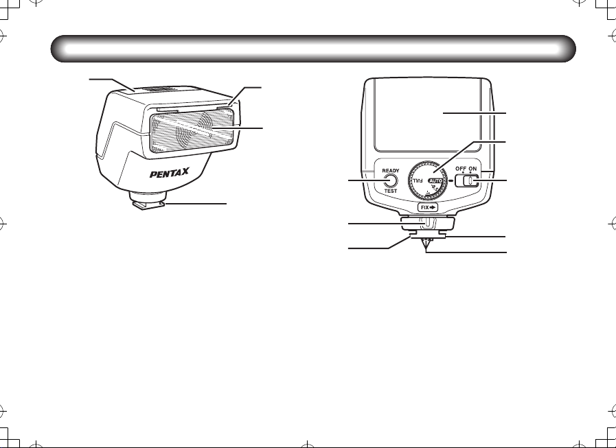
Names of Parts
00_AF200FGZ.book Page 5 Monday, July 30, 2007 9:07 AM
Battery chamber cover
Wide-angle panel
Flash head
Shoe foot
Test button/ Ready lamp
Locking lever
Mode dial
Power switch
Shoe lock pin
Flash signal contacts
(Inner pin)
5
Page 7
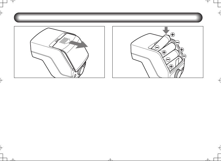
Inserting the Batteries
00_AF200FGZ.book Page 6 Monday, July 30, 2007 9:07 AM
1
Slide the battery chamber cover as shown in the
1
figure and remove it.
6
2
Insert the above four AA batteries sequentially from
2
lower one making sure the plus/minus markings +,
- match the diagram inside the battery chamber
and close the battery chamber cover.
l If you thread the ribbon in the battery chamber
under the batteries beforehand when inserting the
batteries, you can remove the batteries easily by
pulling the ribbon when removing the batteries.
Page 8

n Types of Batteries
00_AF200FGZ.book Page 7 Monday, July 30, 2007 9:07 AM
This flash unit uses four AA batteries of the same type, as
shown below.
Alkaline battery (LR6)
Lithium battery (FR6)
Nickel-Metal Hydride battery (Ni-MH) (Nickel manganese
(Ni-Mn) and nickel cadmium (Ni-Cd) batteries cannot be
used.)
l For information about recycling times and total
number of flashes, refer to “Specifications” on
page 20.
l If the ready lamp does not light up when you turn on
the power (page 8), the batteries may be exhausted
or not inserted correctly. Verify the orientation of the
batteries or, if the indicators and ready lamp still do
not light up, replace them with new batteries.
l If charging time takes more than 20 seconds, the
batteries are exhausted and should be replaced with
new batteries.
l If you let the flash unit discharge successively using
lithium batteries, the batteries will overheat,
activating a safety circuit that temporarily disables
the flash unit. If this occurs, rest the flash unit so
that the temperature of the batteries returns to
normal.
7
Page 9
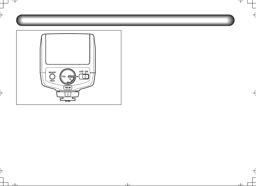
Turning the Power On
00_AF200FGZ.book Page 8 Monday, July 30, 2007 9:07 AM
8
Sliding the power switch to the (ON) position will turn on the
power. The ready lamp will light up when the flash is charged.
Sliding it to the (OFF) position will turn off the power.
Tes t F lash
Check that the ready lamp is lit, then press the test button
(TEST). The test flash will discharge.
Auto Power Off Function
When the flash unit is left unused for about 3 minutes with
the power switch set to the (ON) position, it automatically
turns off to save the power.
Quick Start Function
If the flash unit is mounted on autofocus cameras, press
the shutter release button half way to turn on the power.
Page 10
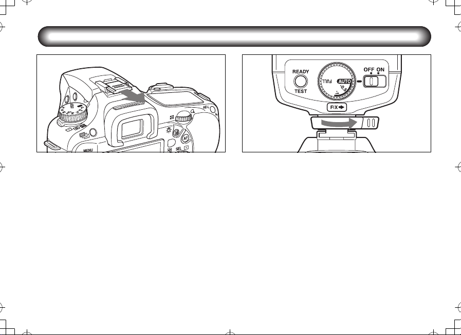
Mounting to Camera
00_AF200FGZ.book Page 9 Monday, July 30, 2007 9:07 AM
1
Remove the hot shoe cover from the camera.
1
Attach the flash unit to the camera.
2
Turn the locking lever of the flash unit in the
direction opposite to that indicated by (FIXÝ).
Slide the hot shoe foot of the flash unit into the
camera's hot shoe from the back of the camera
forward.
Turn the locking lever of the flash unit in the
direction indicated by (FIXÝ) to lock it.
2
l PENTAX digital single lens reflex cameras can
accept a shoe lock pin. When attaching the flash
unit, turn the locking lever in the (FIXÝ) direction
and lock the flash unit to the camera with the shoe
lock pin. When releasing the flash unit, be sure to
do so after turning the locking lever in the direction
opposite to that indicated by (FIXÝ) and loosening
the shoe lock pin. Otherwise, the hot shoe will be
damaged.
9
Page 11

Mode Dial Functions
00_AF200FGZ.book Page 10 Monday, July 30, 2007 9:07 AM
Using the mode dial located on the rear side of the AF200FG, you can set the following flash modes.
Auto flash mode (P-TTL Auto/ TTL Auto)
When the mode dial is set to (AUTO), (–0.5), or (–1), the
operating mode of the flash unit is automatically switched to
P-TTL Auto or TTL Auto by communicating with the camera
you use.
P-TTL Auto flash
A pre-flash is discharged before the main flash so that the
metering sensor in the camera can measure the condition
of the subject and adjust the output of the main flash
properly. This mode gives more accurate results than
the conventional TTL mode.
TTL Auto flash
The metering sensor in the camera measures the amount
of light coming through the lens and adjusts the flash output
properly.
10
Manual flash mode (full output)
When the mode dial is set to (FULL), the flash unit always
discharges at its full output regardless of the ambient light
condition.
Determine the Guide No. of the flash unit based on the ISO
sensitivity setting of the camera, then calculate the aperture
value according to the flash range.
This mode is available on all the cameras for which you can
set the desired aperture.
Page 12
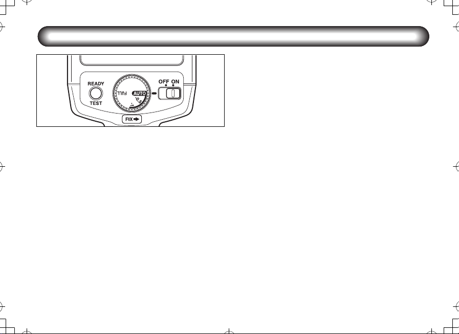
Auto flash shooting
00_AF200FGZ.book Page 11 Monday, July 30, 2007 9:07 AM
Procedure
Slide the Power switch to (ON).
1
Set the mode dial to (AUTO).
2
Confirm that the subject is within the effective flash
3
range and the ready lamp is lit, and take a picture.
l The correct flash output is obtained in P-TTL auto
mode only when the flash unit is used with autofocus lenses.
Set the lens aperture to the position A
in P-TTL Auto mode
When the lens you use is equipped with the lens aperture
ring, set the position of the ring to A (You do not need to do
this for the DA or FAJ lens). Otherwise, the flash unit
cannot function in P-TTL Auto mode.
When you use the cameras that support both P-TTL and
TTL modes (*ist DS2, *ist DS, *ist D) , if the aperture of the
lens is in a position other than A, you can shoot in TTL Auto
flash mode. Be aware that for the cameras that only
support P-TTL Auto flash, the flash unit does not adjust the
flash output but discharges at full output, if the aperture of
the lens is in a position other than A.
About TTL Auto flash mode
With single lens reflex cameras (film cameras) other than
PENTAX digital single lens reflex cameras, you can
perform auto flash shooting if they support TTL Auto.
(However, 35mm cameras before SF series and the 645
camera of the early type do not support the TTL Auto with
this flash unit)
11
Page 13

n Approximate effective flash range in P-TTL Auto flash
00_AF200FGZ.book Page 12 Monday, July 30, 2007 9:07 AM
ISO
sensitivity
ISO 100
ISO 200
ISO 400
ISO 800
ISO 1600
* You can check the approximate range of distances within which the flash unit can adjust the flash output (and the appropriate exposure is
Flash Coverage
Angle
Normal 2.1-14.3 1.5-10.0 1.1-7.1 0.7-5.0 0.7-3.6 0.7-2.5 0.7-1.8 0.7-1.3 0.7-0.9
With the wideangle panel
Normal 3.0-20.0 2.1-14.0 1.5-10.0 1.0-7.0 0.7-5.0 0.7-3.5 0.7-2.5 0.7-1.8 0.7-1.3
With the wideangle panel
Normal 4.2-28.6 3.0-20.0 2.1-14.3 1.5-10.0 1.1- 7.1 0.7-5.0 0.7-3.6 0.7-2.5 0.7-1.8
With the wideangle panel
Normal 6.1-40.7 4.2-28.5 3.0-20.4 2.1-14.3 1.5-10.2 1.1- 7.1 0.8- 5.2 0.7-3.6 0.7-2.6
With the wideangle panel
Normal 8.5-57.1 5.9-40.0 4.2-28.6 3.0-20.0 2.1-14.3 1.5-10.0 1.1- 7.3 0.7-5.0 0.7-3.6
With the wideangle panel
available) based on the combination of the ISO sensitivity setting on the camera and the aperture value from the above table when the mode
dial is set to (AUTO). (The values in "Wide Panel" line indicate the range when the wide-angle panel is used.) Note that the minimum range
that will give correct exposure is 0.7 meters.
1.422.845.68 111622
1.6-10.7 1.1-7.5 0.8-5.4 0.7-3.8 0.7-2.7 0.7-1.9 0.7-1.4 0.7-0.9 0.7-0.7
2.2-15.0 1.6-10.5 1.1-7.5 0.8-5.3 0.7-3.8 0.7-2.6 0.7-1.9 0.7-1.3 0.7-1.0
3.2-21.4 2.2-15.0 1.6-10.7 1.1- 7.5 0.8- 5.4 0.7- 3.8 0.7- 2.7 0.7- 1.9 0.7- 1.4
4.5-30.0 3.1-21.0 2.2-15.0 1.6-10.5 1.1- 7.5 0.8- 5.3 0.7- 3.8 0.7- 2.6 0.7- 1.9
6.4-42.9 4.5-30.0 3.2-21.4 2.2-15.0 1.6-10.7 1.1- 7.5 0.8- 5.5 0.7- 3.8 0.7- 2.7
12
Aperture (F value)
(Unit: m)
Page 14
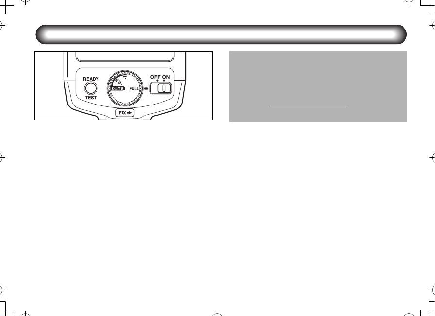
Manual flash shooting
00_AF200FGZ.book Page 13 Monday, July 30, 2007 9:07 AM
Procedure
Slide the Power switch to (ON).
1
Set the mode dial to (FULL).
2
Measure the distance to the subject (between the
3
AF200FG and subject) and determine the aperture
value using the following procedure.(The Guide No.
varies depending on the ISO sensitivity. Refer to the
table on page 14.)
Example: If the subject distance (between the
The Guide No. will be 20.
Aperture = = 8
4
5
AF200FG and subject) is 2.5 m, sensitivity is
ISO 100, and the wide-angle panel is not in
use, the calculation will become as follows:
Guide No.
Subject distance202.5
Set the lens aperture to the calculated value.
Confirm that the ready lamp is lit. Then take a picture.
13
Page 15

n Approximate flash distance in Manual flash
00_AF200FGZ.book Page 14 Monday, July 30, 2007 9:07 AM
ISO
sensitivity
* The appropriate shooting distance (distance at which the appropriate exposure is available) is determined based on the combination of the
ISO sensitivity setting and the aperture value on the camera when the mode dial is set to (FULL). (The values in "Wide Panel" line indicate the
distance when the wide-angle panel is used.) Note that the minimum range that will give correct exposure is 0.7 meters.
Flash Coverage
Angle
Normal 20 14.3 10.0 7.1 5.0 3.6 2.5 1.8 1.3 0.9
100
With the wideangle panel
Normal 28 20.0 14.0 10.0 7.0 5.0 3.5 2.5 1.8 1.3
200
With the wideangle panel
Normal 40 28.6 20.0 14.3 10.0 7.1 5.0 3.6 2.5 1.8
400
With the wideangle panel
Normal 57 40.7 28.5 20.4 14.3 10.2 7.1 5.2 3.6 2.6
800
With the wideangle panel
Normal 80 57.1 40.0 28.6 20.0 14.3 10.0 7.3 5.0 3.6
1600
With the wideangle panel
Normal 113 80.7 56.5 40.4 28.3 20.2 14.1 10.3 7.1 5.1
3200
With the wideangle panel
GN
1.4 2 2.8 4 5.6 8 11 16 22
15 10.7 7.5 5.4 3.8 2.7 1.9 1.4 0.9 0.7
21 15.0 10.5 7.5 5.3 3.8 2.6 1.9 1.3 1.0
30 21.4 15.0 10.7 7.5 5.4 3.8 2.7 1.9 1.4
42 30.0 21.0 15.0 10.5 7.5 5.3 3.8 2.6 1.9
60 42.9 30.0 21.4 15.0 10.7 7.5 5.5 3.8 2.7
85 60.7 42.5 30.4 21.3 15.2 10.6 7.7 5.3 3.9
14
Aperture (F value)
(Unit: m)
Page 16

Application Shooting of Auto Flash
00_AF200FGZ.book Page 15 Monday, July 30, 2007 9:07 AM
n Slow-speed Sync Mode
When using a normal flash to shoot a portrait, etc., in a
night or evening setting, the background will appear very
dark because a normal flash light cannot sufficiently light it.
However, it is possible to balance both subject and
background by using the flash to properly expose the
foreground subject and a slow shutter speed to expose the
low light background.
Camera Model
K100D,
*ist DS/DS2,
*ist DL/DL2
K10D Green mode Set the flash mode of the camera to slow-speed
*ist D Green, P (Hyper Program) and Av (Aperture
- Be sure to make the shutter speeds slower than the X-sync speed.
Shooting Modes Not Supported by
Slow-speed Sync Mode
AUTO PICT, ,
P (Programmed AE), SCN (*ist DL2),
Av (Aperture priority) modes
priority) modes
If your camera supports this mode, you can perform auto
flash shooting. Before shooting, confirm the following.
1. Whether your camera supports slow-speed sync
mode.
2. Whether the shooting mode of your camera
supports slow-speed sync mode.
l Also refer to the operation manual of the camera.
Notes
You can shoot in slow-speed sync mode for up to
one second in mode.
sync mode when the camera is in P (Hyper
Program) , Av (Aperture priority) or Sv (Sensitivity
priority) mode.
You can shoot in slow-speed sync mode when the
camera is in P (Hyper Program) mode if you can
set the shutter speed to 1/150 sec or faster using
the Av dial or Tv dial.
15
Page 17

n Compensating Flash Output
00_AF200FGZ.book Page 16 Monday, July 30, 2007 9:07 AM
When shooting in P-TTL auto flash mode, you can
compensate the flash output using the mode dial on the
flash unit.
If the camera also has the flash output compensation
*
function, and flash output compensation is set both on
the camera and the flash unit, the flash output
compensation amount will be combined.
Refer to the camera operation manual for details.
AUTO : Discharges at the normal output
– 0.5 : Reduces the flash output by 0.5
– 1 : Reduces the flash output by 1 EV.
(flash output compensation is not
set on the flash unit)
EV.
16
Page 18

n Using the Wide-angle Panel
00_AF200FGZ.book Page 17 Monday, July 30, 2007 9:07 AM
The AF200FG has a built-in wide-angle panel. Pull out the
wide-angle panel as shown in the figure.
The wide-angle panel disperses the flash light and expands
flash coverage angle for the wider angle lenses.
As the wide-angle panel reduces the effective flash range,
do not use it when not necessary.
17
Page 19

n Connecting the AF200FG with the
00_AF200FGZ.book Page 18 Monday, July 30, 2007 9:07 AM
Extension Cord
By combining the optional accessories with the flash unit,
you can perform auto flash shooting with the flash unit held
away from the camera.
You can enjoy various auto flash shooting features in
combination with the built-in flash, such as making
shadows by lighting a subject from the side, illuminating the
background, etc.
When you use the AF200FG held away from the camera
connected with an extension cord, use the optional
extension cord F5P/F5P L. Connect the extension cord
F5P/F5P L to the camera with the optional hot shoe
adapter F
it to the flash unit with the off-camenra shoe adapter F
(refer to the diagram on the right).
l When you use the AF200FG in combination with the
18
or the optional hot shoe adapter F, and connect
G
built-in flash unit of the cameras, attach the hot shoe
adapter F
built-in flash unit will not pop up from the camera.
. If you use the hot shoe adapter F, the
G
l If you attach a tripod on the bottom of the remote
flash unit, use the optional off-camera shoe adapter
F. When you set up the remote flash unit on things
such as a tabletop or a chair, etc., use the optional
off-camera shoe clip CL-10.
l If you set the camera such as the K10D, etc. to
trailing curtain sync mode, the setting becomes
invalid when you use the camera with the AF200FG.
Extension cord F5P
Hot shoe
adapter F
G
Page 20

Optional Accessories
00_AF200FGZ.book Page 19 Monday, July 30, 2007 9:07 AM
A number of dedicated accessories are available for this
flash unit.
Off-camera Shoe Clip CL-10
Setting clip for using the AF200FG held away from the
camera.
Hot Shoe Adapter F
Adapter for using the AF200FG as a separate flash unit
using the extension cord F5P/F5P L. It can be used in
combination with the built-in flash unit.
Off-camera shoe adapter F
Adapter for attaching an external flash unit, etc. on a tripod
separated from the camera. It comes with a connector for
the extension cord F5P/F5P L.
Hot Shoe Adapter F
Adapter for connecting the camera and extension cord
F5P/F5P L. It also has a hot shoe on its top.
G
Extension Cord F5P – 0.5m/1.5m/L (Approx. 3m)
5P synchro cord to use a flash unit for single lens reflex
camera, such as the AF540FGZ, AF360FGZ or AF200FG,
held away from the camera. It is used in combination with
the hot shoe adapter F
adapter F.
or F, and/or the off-camera shoe
G
Hot Shoe Grip 67II
Adapter for positioning a flash unit such as the AF540FGZ,
AF360FGZ or AF200FG alongside the 67II camera body. It
connects to the 67II’s 5P sync terminal with the included 5P
Sync Cord.
19
Page 21

Specifications
00_AF200FGZ.book Page 20 Monday, July 30, 2007 9:07 AM
Typ e Clip-on, TTL auto flash unit with series control
Cameras supporting the Auto
flash shooting • Digital SLR series
Guide No. Maximum 20 (ISO 100/m)
Recycling time/Total number of
flashes
Flash Coverage Angle Vertical Angle: 26.5°, Horizontal Angle: 35°(When the wide-angle panel is used: Vertical Angle:
20
• 35mm (Film) Autofocus SLR after Z series
• 645N, 645N II, and 67 II
ISO
DIGITAL 19mm 16mm
100 (FULL) 20 15
200 (FULL) 28 21
400 (FULL) 40 30
800 (FULL) 57 42
1600 (FULL) 80 60
3200 (FULL) 113 85
Battery type Recycling time Total number of flashes
AA Alkaline (LR6) Approx. 4 sec. Approx. 300
AA Nickel-Metal Hydride (Ni-
MH/2700mAh)
AA Lithium (FR6) Approx. 4 sec. Approx. 450
30°, Horizontal Angle: 39°)
Format Normal With the wide-angle panel
35mm 28mm 24mm
645 55mm 45mm
67 70mm 60mm
Approx. 4 sec. Approx. 400
Page 22

Color temperature Daylight (Suited for daylight color film)
00_AF200FGZ.book Page 21 Monday, July 30, 2007 9:07 AM
Effective flash range Approx. 0.7 m - approx. 3.6 m (Guide No. 20, ISO 100, f/5.6)
ISO sensitivity setting ISO 100 - 1600 (In P-TTL mode)
Flash modes P-TTL auto, TTL auto, manual (FULL)
Flash output compensation –0.5 or –1.0EV (switches with the mode dial)
Power saving Automatic power-off
Red-eye reduction Operates with auto-focus cameras equipped with red-eye reduction feature.
Wide-angle panel Pull out manually.
Power source Four AA batteries, (Alkaline (LR6), Nickel-Metal Hydride (Ni-MH), or Lithium (FR6))
Dimensions and weight 68 mm (W) × 83.5 mm (H) × 93 mm (T) (2.7'' × 3.3'' × 3.7''), Approx. 190 g (6.8 oz.) without
batteries
21
Page 23

Appendix
00_AF200FGZ.book Page 22 Monday, July 30, 2007 9:07 AM
Table of dedicated functions at Auto flash shooting
Camera type K10D, K100D, *ist DL2, *ist DL *ist DS2, *ist DS, *ist D
Flash Mode
Leading curtain sync
Trailing curtain sync
High-speed sync
Slow-speed sync
Automatic switching to X-sync
speed when flash is charged
Flash ready display in
viewfinder
Auto check display
Red-eye reduction
Flash output compensation
using the mode dial on the flash
unit
Yes : A v ail a b l e
No : Not available
* For the *ist DS2, *ist DS or *ist D camera, the flash mode is switched from P-TTL to TTL, if the aperture of the lens is in
a position other than A.
* The setting of trailing curtain sync mode on the K10D camera becomes invalid when you use the camera with the AF200FG.
22
P-TTL auto
flash mode
Yes
No No No No
No No No No
Yes
Yes Yes Ye s Yes
Yes Yes Ye s Yes
No No No
Yes Yes Ye s Yes
Yes N o Ye s No
TTL auto
flash mode
No
No
P-TTL auto
flash mode
Yes Ye s
Yes Ye s
TTL auto
flash mode
Yes
Page 24

Warranty Policy
00_AF200FGZ.book Page 23 Monday, July 30, 2007 9:07 AM
All PENTAX camera accessories purchased through authorized bona fide photographic distribution channels are guaranteed against
defects of material or workmanship for a period of twelve months from date of purchase. Service will be rendered, and defective parts
will be replaced without cost to you within that period, provided the equipment does not show evidence of impact, sand or liquid
damage, mishandling, tampering, battery or chemical corrosion, operation contrary to operating instructions, or modification by an
unauthorized repair shop. The manufacturer or its authorized representatives shall not be liable for any repair or alterations except
those made with its written consent and shall not be liable for damages from delay or loss of use or from other indirect or consequential
damages of any kind, whether caused by defective material or workmanship or otherwise; and it is expressly agreed that the liability of
the manufacturer or its representatives under all guarantees or warranties, whether expressed or implied, is strictly limited to the
replacement of parts as herein before provided. No refunds will be made on repairs performed by non-authorized PENTAX service
facilities.
Procedure During 12-month Warranty Period
Any PENTAX which proves defective during the 12-month warranty period should be returned to the dealer from whom you purchased
the equipment or to the manufacturer. If there is no representative of the manufacturer in your country, send the equipment to the
manufacturer, with postage prepaid. In this case, it will take a considerable length of time before the equipment can be returned to you
owing to the complicated customs procedures required. If the equipment is covered by warranty, repairs will be made and parts
replaced free of charge, and the equipment will be returned to you upon completion of servicing. If the equipment is not covered by
warranty, regular charges of the manufacturer or of its representatives will apply. Shipping charges are to be borne by the owner. If
your PENTAX was purchased outside of the country where you wish to have it serviced during the warranty period, regular handling
and servicing fees may be charged by the manufacturer’s representatives in that country. Notwithstanding this, your PENTAX returned
to the manufacturer will be serviced free of charge according to this procedure and warranty policy.
In any case, however, shipping charges and customs clearance fees are to be borne by the sender. To prove the date of your purchase
when required, please keep the receipts or bills covering the purchase of your equipment for at least a year. Before sending your
equipment for servicing, please make sure that you are sending it to the manufacturer’s authorized representatives or their approved
repair shops, unless you are sending it directly to the manufacturer. Always obtain a quotation for the service charge, and only after
you accept the quoted service charge, instruct the service station to proceed with the servicing.
23
Page 25

This warranty policy does not affect customer’s statutory rights.
00_AF200FGZ.book Page 24 Monday, July 30, 2007 9:07 AM
The local warranty policies available from PENTAX distributors in some countries can supersede this warranty policy. Therefore, we
recommend that you review the warranty card supplied with your product at the time of purchase, or contact the PENTAX distributor in
your country for more information and to receive a copy of the warranty policy.
For customers in the USA
STATEMENT OF FCC COMPLIANCE
This device complies with Part 15 of the FCC Rules. Operation is subject to the following two conditions: (1) This device may not cause
harmful interference, and (2) this device must accept any interference received, including interference that may cause undesired
operation.
Changes or modifications not approved by the party responsible for compliance could void the user’s authority to operate the
equipment.
This equipment has been tested and found comply with the limits for a Class B digital device, pursuant to part 15 of the FCC Rules.
These limits are designed to provide reasonable protection against harmful interference in a residential installation. This equipment
generates, uses and can radiate frequency energy and, if not installed and used in accordance with the instructions, may cause
harmful interference to radio communications. However, there is no guarantee that interference will not occur in a particular
installation. If this equipment does not cause harmful interference to radio or television reception, which can be determined by turning
the equipment off and on, the user is encouraged to try to correct the interference by one or more of the following measures:
• Reorient or relocate the receiving antenna.
• Increase the separation between the equipment and receiver.
• Consult the dealer or an experienced radio/TV technician for help.
For customers in Canada
This Class B digital apparatus complies with Canadian ICES-003.
Pour les utilisateurs an Canada
Cet appareil numérique de la classe B est conforme à la norme NMB-003 du Canada.
24
Page 26

Information on disposal for users
00_AF200FGZ.book Page 25 Monday, July 30, 2007 9:07 AM
1. In the European Union
If your product is marked with this symbol, it
means that used electrical/electronic
products should not be mixed with general
household waste. There exists a separate
collection system for these products.
Used electric/electronic equipment must be treated
separately and in accordance with legislation that requires
proper treatment, recovery and recycling of these products.
Following the implementation by member states, private
households within the EU states may return their used
electrical/electronic equipments to designated collection
facilities free of charge*. In some countries your local
retailer may also take back your old product free of charge
if you purchase a similar new one.
*Please contact your local authority for further details.
By disposing of this product correctly you will help ensure
that the waste undergoes the necessary treatment,
recovery and recycling and thus prevent potential negative
effects on the environment and human health which could
otherwise arise due to inappropriate waste handling.
2. In other countries outside the EU
If you wish to discard this product, please contact your local
authorities and ask for the correct method of disposal.
For Switzerland: Used electrical/electronic equipment can
be returned free of charge to the dealer, even when you
don’t purchase a new product. Further collection facilities
are listed on the home page of www.swico.ch
www.sens.ch
or
25
 Loading...