

Page 1
AF160FC.book Page 1 Monday, November 17, 2008 9:41 AM
Introduction
Thank you for purchasing the PENTAX Auto Macro Flash
AF160FC.
The AF160FC is a flash system for taking close-up photos of
small subjects using a flash to eliminate shadows, allowing you
to really enjoy photography. This operating manual is intended
mainly for digital SLR cameras using the P-TTL auto flash
mode. However, the flash unit is also compatible with the TTL
auto flash and the provided adapter rings make it available for
use with many PENTAX products.
Please read this operation manual carefully before using your
flash unit.
PENTAX is a registered trademark of HOYA CORPORATION.
はじめに
このたびは、ペンタックス・オートマクロストロボAF160FC
をお買い上げいただき、誠にありがとうございます。
AF160FCは近接撮影用に用意されたストロボシステムで、小
さな被写体の無影撮影など、手軽にお楽しみいただけます。本
書は主にP-TTL オートストロボ機能に対応したデジタル一眼
レフカメラを対象に説明をしていますが、従来のTTLオートス
トロボ機能にも対応しており、同梱のアダプターリングと組み
合わせて、幅広くペンタックス製品にご利用いただけます。
ご使用前にこの使用説明書をよくお読みのうえ、正しくお使い
ください。
「PENTAX」「ペンタックス」はHOYA株式会社の登録商標です。
1
Page 2
AF160FC.book Page 2 Monday, November 17, 2008 9:41 AM
FOR THE SAFE USE OF YOUR FLASH UNIT
Although we have carefully produced this flash unit for safe
operation, please be sure to especially follow warnings and
cautions given on page 3.
WARNING
This symbol indicates that violating this item could cause
serious personal injuries.
CAUTION
This symbol indicates that violating this item could cause minor
or medium personal injuries, or material losses.
is a symbol indicating items that are prohibited.
is a symbol emphasizing a warning.
2
ストロボを安全にお使いいただくために
この製品の安全性については十分注意を払っておりますが、3
ページにある下記マークの内容については特に注意をしてお
使いください。
警告
このマークの内容を守らなかった場合、人が重大な傷害を受け
る可能性があることを示すマークです。
注意
このマークの内容を守らなかった場合、人が軽傷または中程度
の傷害を受けたり、物理的損害の可能性があることを示すマー
クです。
は、禁止事項を表わすマークです。
は、注意を促すためのマークです。
Page 3
AF160FC.book Page 3 Monday, November 17, 2008 9:41 AM
Warning
The flash contains electronic circuits that operate at
high voltages. Do not attempt to disassemble the flash
unit yourself, as there is danger of an electric shock.
If internal parts of the flash unit become exposed due to
impact, etc., do not touch them as there is danger of an
electric shock.
Do not expose the flash unit to water or moisture as
there is danger of an electric shock.
Caution
Do not use the flash near anyone's eyes, as it may hurt
them. Be particularly careful with the flash around
infants.
The following may lead to an explosion or fire.
l Shorting the batteries
l Exposing the batteries to flames
l Dismantling the batteries
l Attempting to recharge non-rechargeable batteries
Remove the batteries from the flash unit immediately if
they become hot or begin to smoke. Be careful not to
burn yourself during removal.
警告
ストロボを分解しないでください。ストロボ内部には高
電圧部があり、感電の危険があります。
落下などにより、ストロボ内部が露出したときは、絶対
に露出部分に手をふれないでください。感電の危険があ
ります。
ストロボを水に濡らさないでください。感電の危険があ
ります。
注意
目の近くでストロボを発光させないでください。目を痛
めることがあります。特に、乳幼児にはご注意ください。
電池をショートさせたり、火の中に入れないでくださ
い。また、分解や充電をしないでください。破裂・発火
の恐れがあります。
ストロボ内の電池が発熱・発煙を起こしたときは、速や
かに電池を取り出してください。この場合、やけどに十
分ご注意ください。
3
Page 4
AF160FC.book Page 4 Monday, November 17, 2008 9:41 AM
Precautions for Your Flash Unit
l Never use organic solvents such as paint thinner, alcohol
or benzene to clean the flash unit.
l Avoid leaving the flash unit for extended periods in places
where the humidity and temperature may be very high
such as in a car.
l Be careful not to subject the flash unit to strong vibrations,
shock or pressure. Use a cushion to protect the flash unit
when carrying it in a motorcycle, car, boat, etc.
l Do not use the flash unit where it may be directly exposed
to rain, water, etc.
l Replace all the batteries at the same time. Do not mix
battery brands, type or an old battery with a new one.
It may cause explosion or overheating.
l When using the flash unit off the camera, do not try to
attach any metallic object to the electric contacts or to
mount incompatible accessories. Otherwise, the TTL auto
mechanism may be damaged or rendered inoperable.
l Do not attach any accessories having either fewer or
different electrical contacts (layout other than PENTAX
standard) for the hot shoe or grip. Otherwise, some
functions may not work properly.
4
取り扱い上の注意
l 汚れ落としに、シンナーやアルコール・ベンジンなどの有
機溶剤は使用しないでください。
l 高温多湿の所は避けてください。特に車の中は高温になり
ますのでご注意ください。
l 強い振動・ショック・圧力などを加えないでください。オー
トバイ・車・船などの振動は、クッションなどを入れて保
護してください。
l 雨水などが直接かかるところでは使用できません。
l 新旧の電池を混ぜないでください。また、違う種類の電池
を混ぜないでください。
l ストロボをカメラから離して使う場合、信号接点に金属が
触れないようにしてください。TTLオートが正しく働かな
くなります。
l 接点数の異なるアクセサリー(ホットシューグリップな
ど)を接続しないでください。一部の機能が正しく働かな
くなることがあります。
l 他社製カメラを本製品に使用されたことによる事故、故障
などにつきましては保証いたしかねます。
l 高性能を保つため、1 ~2 年毎に定期点検をしてください。
長期間使用しなかったときや、大切な撮影の前には点検や
テスト発光をしてください。
Page 5
AF160FC.book Page 5 Monday, November 17, 2008 9:41 AM
l We will not be held responsible for any accidents or
damage, etc. caused by using this product with cameras
and accessories made by other companies.
l Periodic checks are recommended every 1 to 2 years in
order to maintain high performance. If the unit has not
been used for an extended period of time, or is being
readied for an important shoot, it is recommended that you
take a test flash with the TEST button and test shoot with
it. Test flash is also important to maintain optimum
performance.
l Avoid contact with garbage, dirt, sand, dust, water, toxic
gases, salt, etc. When the flash unit is subjected to rain
or moisture, wipe it off with a dry soft cloth.
l Remove the batteries when not using the flash unit for
extended periods. Otherwise, battery leakage might result
and cause damage to the circuitry and proper operation
of the flash unit.
l Battery performance may temporarily be hindered in low
temperatures. Batteries should be kept warm in
temperatures below freezing for proper performance.
l When photographing black subjects or white subjects,
use exposure compensation.
l ゴミや泥・砂・ホコリ・水・有害ガス・塩分などがストロ
ボの中に入らないようにご注意ください。故障の原因にな
ります。雨や水滴などが付いたときは、よく拭いて乾かし
てください。
l 長期間使用しないときは、電池を取り出しておいてくださ
い。液漏れなどでストロボ内部を傷めることがあります。
l 寒冷地では、電池を保温しながら使用してください。電池
の性能が低下します。
l 黒い被写体や白い被写体などでは、光量補正などを利用し
て、撮影してください。
5
Page 6
AF160FC.book Page 6 Monday, November 17, 2008 9:41 AM
Introduction......................................................................................... 1
Contents
FOR THE SAFE USE OF YOUR FLASH UNIT.................................. 2
Precautions for Your Flash Unit.......................................................... 4
Overview of the operating manual...................................................... 9
Packing list........................................................................................ 10
Using the case .................................................................................. 11
Names of parts (Controller) .............................................................. 12
Names of parts (Flash head) ............................................................ 13
Getting ready 14
Inserting the Batteries....................................................................... 14
n About battery types .................................................................................. 15
Charge check and test flash ............................................................. 17
n How to check the charge ................................................................... ...... 17
n How to test the flash unit .................... ..................................................... 17
n About auto power off. ............................................................................ ... 17
How to mount the macro flash unit ................................................... 18
n Attach the controller to the camera. ......................................................... 18
n Attach the adapter to the lens that is on the camera................................ 20
n Attach the flash head to the adapter ........................................................ 22
Taking pictures 23
Mode dial functions........................................................................... 23
Taking pictures in auto flash mode ................................................... 24
n Auto flash modes ..................................................................................... 24
n Auto flash operations for various cameras............................................... 25
n Procedure........................................................... ...................................... 26
n TTL auto flash compatible cameras. ........................................................ 27
n Compensating flash output with the mode dial ........................................ 27
6
Taking pictures in manual flash mode............................................... 28
n ISO sensitivity and guide numbers ........................................................... 28
n About exposure values ............................................................................. 28
n Conditions of the subject change exposure values................................... 29
n Compensating flash output with the mode dial ......................................... 29
n Procedure .......................................................................................... ....... 29
Other functions 30
Using the flash head output switch.................................................... 30
About the modeling light.................................................................... 31
Appendix 32
Auto flash guidelines and calculation methods ................................. 32
Manual flash guidelines and calculation methods ............................. 33
Lenses with compatibility issues ....................................................... 36
Specifications .................................................................................... 40
Warranty Policy ................................................................................. 41
Page 7

AF160FC.book Page 7 Monday, November 17, 2008 9:41 AM
はじめに ............................................................................................. 1
ストロボを安全にお使いいただくために........................................... 2
取り扱い上の注意............................................................................... 4
本書の構成.......................................................................................... 9
同梱品一覧........................................................................................ 10
ケースの使いかた............................................................................. 11
各部の名称(コントローラー)......................................................... 12
各部の名称(発光部ユニット)......................................................... 13
準備する 14
電池の入れ方 .................................................................................... 14
n 電池の種類について............................ ..................................................... 15
充電確認とテスト発光...................................................................... 17
n 充電確認のしかた .................... ................................................................ 17
n テスト発光のしかた............................ ..................................................... 17
n オートパワーオフ機能について......................... ...................................... 17
マクロストロボの取り付けかた ....................................................... 18
n コントローラーをカメラ本体に取り付ける..................... ........................ 18
n カメラに装着されたレンズにアダプターを取り付ける..................... ...... 20
n アダプターに発光部ユニットを取り付ける..................... ........................ 22
撮影する 23
モードダイヤルについて .................................................................. 23
オートストロボモードで撮影する.................................................... 24
n オートストロボモードの種類 ................ .................................................. 24
n カメラ別のオートストロボ動作モードについて ..................................... 25
n 撮影手順................................ ................................................................... 26
n TTLオートストロボ対応カメラについて .............................................. ... 27
n モードダイヤルでストロボの発光量を補正する ..................................... 27
目 次
マニュアルストロボモードで撮影する ............................................. 28
n ISO 感度とガイドナンバー........................................................................ 28
n 露出 倍数について ......................................................... ............................ 28
n 被写 体条件で露出値は変わります......... ................................................... 29
n モー ドダイヤルでストロボの発光量を補正する ...................... ................ 29
n 撮影 手順................................................................... ................................. 29
その他の機能 30
発光部切り替えスイッチの使いかた................................................. 30
イルミネーター(モデリング照明)について .................................. 31
付録 32
オート撮影時の目安表・計算方法 .................................................... 32
マニュアル撮影の目安表・計算方法................................................. 34
使用に適さないレンズ ...................................................................... 38
主な仕様 ............................................................................................ 40
アフターサービスについて ............................................................... 41
7
Page 8
AF160FC.book Page 8 Monday, November 17, 2008 9:41 AM
8
Page 9
AF160FC.book Page 9 Monday, November 17, 2008 9:41 AM
Overview of the operating manual
The operating manual includes the following chapters.
1 Getting ready –––––––––––––––––––––––––––––––––––
This chapter explains about getting ready to take pictures after you purchase
the flash unit.
Be sure to read this chapter before you start taking pictures or operating the flash unit.
2 Taking pictures––––––––––––––––––––––––––––––––––
This chapter explains how to take pictures and how to set the functions for
taking pictures.
3 Other functions –––––––––––––––––––––––––––––––––
This chapter explains how to use the functions of the flash unit.
4 Appendix–––––––––––––––––––––––––––––––––––––––
The appendix includes materials, data tables, and specifications.
本書の構成
本書は、次の章で構成されています。
1 準備する –––––––––––––––––––––––––––––––––––––––
お買い上げ後、本機を使った撮影のための準備について説明しています。
撮影をはじめる前に必ずお読みになり、操作を行ってください。
2 撮影する –––––––––––––––––––––––––––––––––––––––
撮影の種類と手順、撮影に関する機能の設定方法について説明しています。
3 その他の機能 ––––––––––––––––––––––––––––––––––––
本機に付随する機能とその使いかたについて説明しています。
4 付録 –––––––––––––––––––––––––––––––––––––––––––
各種資料やデータ表、仕様などを記載しています。
1
2
3
4
9
Page 10
AF160FC.book Page 10 Monday, November 17, 2008 9:41 AM
123
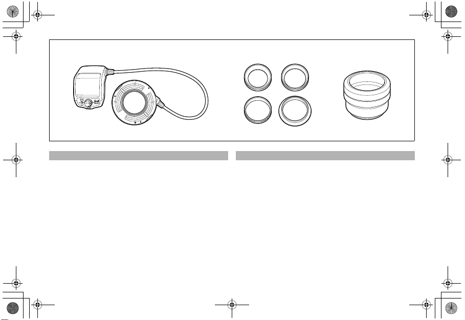
Packing list
Make sure that everything on the list is in the package. Contact
the retailer where you purchased the flash unit if anything is
missing or damaged.
1 Macro flash (controller and flash head)
2 Adapter ring (4 types: 49 mm, 52 mm, 58 mm, and 67 mm)
3 Macro adapter (for D-FA macro lens)
4 Operating manual (this booklet)
5 Case
6 Warranty
10
同梱品一覧
箱の中身を確認してください。不足しているもの、破損してい
るものがある場合はお買い上げいただいた販売店にご連絡く
ださい。
1 本体(コントローラー、発光部ユニット)
2 アダプターリング(4点:49mm、52mm、58mm、67mm)
3 マクロアダプター(D-FAマクロレンズ用)
4 使用説明書(本書)
5 ケース
6 保証書
Page 11
AF160FC.book Page 11 Monday, November 17, 2008 9:41 AM
Using the case
Macro Adapter
マクロアダプター
Adapter Rings
アダプターリング
Flash Head
発光部ユニット
ケースの使いかた
Controller
コントローラー部
AA Batteries (Optional)
単3形電池 (別売)
11
Page 12
AF160FC.book Page 12 Monday, November 17, 2008 9:41 AM
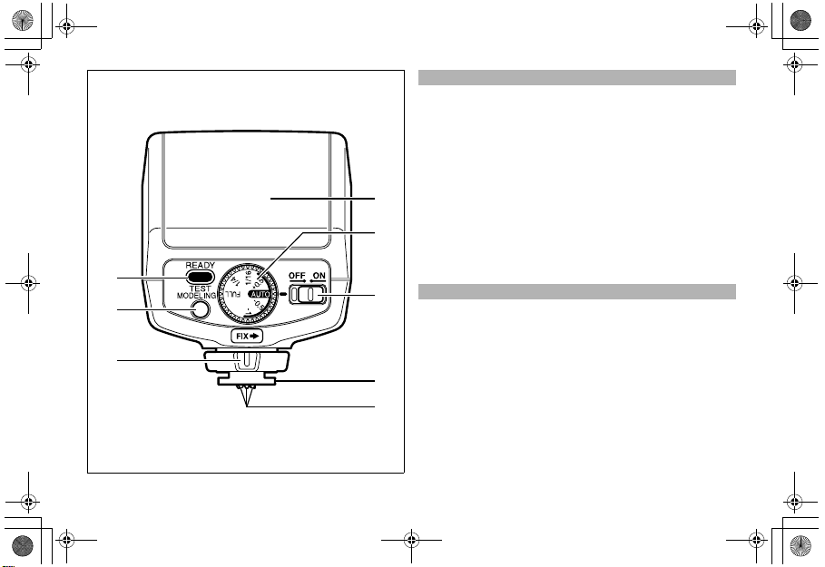
Names of parts (Controller)
1 Battery chamber cover
2 Mode dial: Selects the flash mode. (P.23)
3 Power switch (P.17)
4 Flash shoe
5 Flash signal contacts
6 READY lamp/TEST button (P.17)
Lights when charging is finished. Press to test the flash.
7 MODELING button (P.31)
1
Turns the modeling light on the flash head on and off.
8 Locking lever (P.19)
2
6
7
8
12
各部の名称(コントローラー)
3
1 電池ぶた
2 モードダイヤル:発光モードを選択します。(P.23)
3 電源スイッチ(P.17)
4 シューブラケット
5 ストロボ信号接点
6 READYランプ/TESTボタン(P.17)
4
5
充電が完了すると点灯します。押すとテスト発光します。
7 MODELINGボタン(P.31)
発光部ユニットのモデリングライトをON/OFFします。
8 締め付けノブ(P.19)
Page 13
AF160FC.book Page 13 Monday, November 17, 2008 9:41 AM
1
3
4
22
4
22
4
4
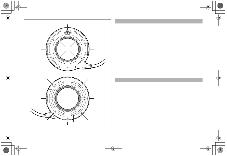
Names of parts (Flash head)
1 Flash head output switch (P.30)
2 Release button (P.22)
3 Mounting tabs (4 positions)
4 Modeling light (LED)
5 Flash lamps
各部の名称(発光部ユニット)
1 発光部切り替えスイッチ(P.30)
2 着脱ボタン(P.22)
3 取り付け爪(4ヶ所)
4 モデリングライト(LED)
5 発光部
5
13
Page 14
AF160FC.book Page 14 Monday, November 17, 2008 9:41 AM
1
12
1 Getting ready
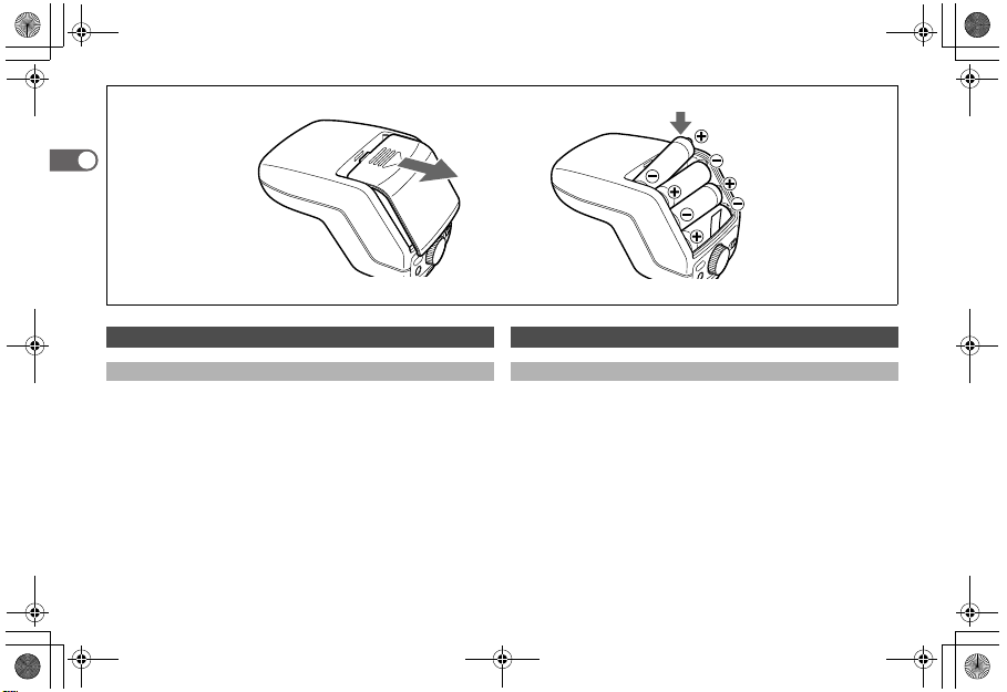
Inserting the Batteries
1 Slide the battery chamber cover as shown in the figure and
remove it.
2 Insert the above four AA batteries sequentially from lower
one making sure the plus/minus markings +, - match the
diagram inside the battery chamber and close the battery
chamber cover.
l If you thread the ribbon in the battery chamber under the
batteries beforehand when inserting the batteries, you
can remove the batteries easily by pulling the ribbon
when removing the batteries.
14
1 準備する
電池の入れ方
1 図のように電池ぶたをスライドさせて取り外します。
2 単3 形電池を4本、+-の表記に合わせて下から順番に入れ
ます。
入れ終わったら手順1と反対の手順で電池ぶたを閉じます。
l 電池を入れる際に、電池室内のリボンを電池の下に通してお
くと、電池を取り出す際にリボンの先端を引っ張って、簡単
に取り出すことができます。
Page 15

AF160FC.book Page 15 Monday, November 17, 2008 9:41 AM
n About battery types
l Compatible batteries
Use four of the same type of battery.
• AA alkaline batteries (LR6)
• AA lithium batteries (FR6)
• AA Nickel-Metal Hydride (Ni-MH) batteries
l Non-compatible batteries
The following batteries cannot be used in the flash unit.
• AA manganese batteries
• AA nickel cadmium batteries (Ni-Cd)
l Recycling times and total number of flashes according to
type of battery
Battery type
AA alkaline batteries (LR6) Approx. 7 sec. Approx. 150
AA lithium batteries (FR6) Approx. 7 sec. Approx. 250
AA Nickel-Metal Hydride
(Ni-MH/2700mAh) batteries
* These figures are for new batteries that are the same type.
Recycling
Approx. 7 sec. Approx. 200
time
Tot al n um be r
of flashes
Note
• If the READY lamp does not light up soon after turning on the
power switch, the batteries may be exhausted or inserted
incorrectly.
Verify the orientation of the batteries, or if the READY lamp
still does not light up, replace them with new batteries.
• If charging takes more than 20 seconds, the batteries are
exhausted. The batteries need to be replaced.
n 電池の種類について
l 使える電池
同じ種類のものを4本使用します。
• 単3形アルカリ電池(LR6)
• 単3形リチウム電池(FR6)
• 単3形ニッケル水素電池(Ni-MH)
l 使えない電池
以下の種類の電池は使えません。
• 単3形マンガン電池
• 単3形ニッカド電池(Ni-Cd)
l 電池の種類別の発光間隔と発光回数
電池の種類 発光間隔 発光回数
単3形アルカリ電池(LR6)約7秒約150回
単3形リチウム電池(FR6)約7秒約250回
単3形ニッケル水素電池
(Ni-MH/2700mAh)
約7秒約200回
※すべて同じ種類の新品の電池を使用した場合
注意
• 電源スイッチを ON にしても READY ランプが点灯しないと
きは、電池が正しく入っていないか、消耗している可能性が
あります。
電池の向きを確認して、それでも点灯しない場合は新しい電
池に交換してください。
• 充電に20秒以上かかるときは電池が消耗しています。新しい
電池に交換してください。
• リチウム電池(FR6)でストロボを連続使用して発光させる
と、電池の発熱により安全回路が働き、一時的にご使用いた
1
15
Page 16

AF160FC.book Page 16 Monday, November 17, 2008 9:41 AM
• If you discharge the flash unit repeatedly when using lithium
batteries, the batteries will overheat and activate a safety
circuit that temporarily disables the flash unit. If this occurs,
wait until the batteries cool down before using the flash unit
1
again.
• Do not use different types of batteries at the same time. Also,
do not combine old batteries with new batteries even if they
are the same type.
• Remove the batteries if you are not going to use the flash unit
for a long time.
16
だけなくなることがあります。この場合、しばらく時間をお
いて電池の温度が下がると、問題なく使用できるようになり
ます。
• 種類の異なる電池を混ぜないでください。また、同じ種類の
電池でも新しいものと古いものを混ぜて使わないでくださ
い。
• 長時間使用しないときは、電池を取り出してください。
Page 17

AF160FC.book Page 17 Monday, November 17, 2008 9:41 AM
A:B:
1
Charge check and test flash
Insert the batteries and then do a test flash.
n How to check the charge
Insert the batteries and then turn on the power.
The READY lamp will light up when the flash is charged.
n How to test the flash unit
When the READY lamp lights, press the READY lamp/TEST
button.
If the flash unit fires, there is no problem.
n About auto power off
The flash unit is equipped with an auto power off function.
The flash unit automatically turns off to save power if it is not
used for about three minutes.
(A:)
(B:)
充電確認とテスト発光
電池をセットしたら、テスト発光を行います。
n 充電確認のしかた
電池をセットした状態で、電源スイッチをONにする。
READYランプが点灯すれば充電完了です。
n テスト発光のしかた
READYランプが点灯している状態で、TESTボタンを押す。
発光すれば問題ありません。
n オートパワーオフ機能について
このストロボにはオートパワーオフ機能が搭載されています。
電源スイッチをON にした状態で約3 分間何も操作を行わない
と電池節約のため自動的に電源をOFFにします。
(A:)
(B:)
17
Page 18

AF160FC.book Page 18 Monday, November 17, 2008 9:41 AM
1
1 2
How to mount the macro flash unit
Attach the lens you are going to use before mounting the macro
flash.
There are three steps for mounting the flash unit.
1 Attach the controller to the camera.
2 Attach the adapter to the lens that is on the camera.
3 Attach the flash head to the adapter
This section explains them in order.
n Attach the controller to the camera.
1 Remove the flash shoe cover from the camera.
Keep the flash shoe cover safe and do not lose it.
18
マクロストロボの取り付けかた
あらかじめ、カメラに使用するレンズを装着しておいてくださ
い。
取り付け方法は大きく3つのステップに分かれます。
1 コントローラーをカメラ本体に取り付ける
2 カメラに装着されたレンズにアダプターを取り付ける
3 アダプターに発光部ユニットを取り付ける
順番に説明します。
n コントローラーをカメラ本体に取り付ける
1 カメラのホットシューカバーを外します。
ホットシューカバーはなくさないように保管してくださ
い。
Page 19

AF160FC.book Page 19 Monday, November 17, 2008 9:41 AM
43
1
2 Turn the locking lever of the controller away from [FIX Ý].
Loosen it so the flash shoe mounts easily.
3 Slide the flash shoe of the controller into the camera's hot
flash shoe from the back of the camera.
Insert it all the way until it stops.
4 Turn the locking lever of the controller toward [FIX Ý].
* Do this procedure in reverse to remove the flash unit. The
flash unit uses a lock pin mechanism. Because of this,
removing the flash unit without loosening the lock lever may
damage the flash shoe of cameras that have the lock-pin
mechanism. Be sure to loosen the lock lever before removing
the flash unit.
2 コントローラーの締め付けノブを[FIXÝ]と反対方向に回
します。
シューブラケットが挿入しやすいように緩めます。
3 コントローラーのシューブラケットをカメラのホット
シューに後方から差し込みます。
突き当たるまでしっかりと差し込んでください。
4 コントローラーの締め付けノブを[FIXÝ]方向に回して固
定します。
※取り外す際は手順を逆にしてください。本機は、ロック
ピン機構を採用しています。このため、ロックピン機構
に対応しているカメラでは、締め付けノブを緩めないで
無理に外そうとするとホットシューが壊れます。必ず締
め付けノブを緩めてから本機を外してください。
19
Page 20

AF160FC.book Page 20 Monday, November 17, 2008 9:41 AM
1
B:A:
n Attach the adapter to the lens that is on the camera.
l Types of adapters
The adapters that can be used vary depending on the type of
lens. There are two types of adapters provided.
• A: Adapter ring: Attaches to the filter mounting thread on the
front of lenses (screw type)
Adapter rings are provided in four diameters: 49 mm, 52 mm,
58 mm and 67 mm.
• B: Macro adapter: For the D-FA macro lens, mounts on the
bayonet for the hood.
20
n カメラに装着されたレンズにアダプターを取り付ける
l アダプターの種類
レンズの種類によって、使用するアダプターが異なります。タ
イプ別に2種類のアダプターがあります。
•A: アダプターリング:レンズの先端にあるフィルター取り付
け枠に装着する(ねじ込む)タイプ
レンズの口径別に4 種類(49mm、52mm、58mm、67mm)
が同梱されています。
•B: マクロアダプター:D-FA マクロレンズ用で、フード取り
付けバヨネットに装着するタイプ
Page 21

AF160FC.book Page 21 Monday, November 17, 2008 9:41 AM
B:A:
1
This section explains how to mount these types of adapters.
l Mounting procedure
A: Adapter ring
Screw the adapter ring that is the same size as the lens onto
the front thread of the lens.
B: Macro adapter
1 Line up the macro adapter with the bayonet (hood mount) on
the lens front, and push the adapter straight on.
2 To mount the macro adapter, turn it clockwise (while facing
it) until you hear it click.
アダプターの種類別に取り付けかたを説明します。
l 取り付けかた
A:アダプターリング
レンズの前枠にレンズの口径に合ったアダプターリングを
ねじ込んで取り付けます。
B:マクロアダプター
1 マクロアダプターをレンズ側のバヨネット(取り付けツメ)
に合わせて、まっすぐに押し込みます。
2 マクロアダプターを正面から見て時計方向に「カチッ」と
音がするまで回転させて固定します。
21
Page 22

AF160FC.book Page 22 Monday, November 17, 2008 9:41 AM
1
B:A:
n Attach the flash head to the adapter
Press the release buttons on the flash head to insert the four
mounting tabs (circled in the above diagram) on the inside of the
flash head correctly into the groove on the adapter ring (A) or
macro adapter (B).
After the flash head is attached, pull it lightly to make sure the
tabs are inserted into the groove correctly.
The mounting tabs go into this groove.
22
n アダプターに発光部ユニットを取り付ける
発光部ユニットの左右にある着脱ボタンを押しながら、アダプ
ターリング(A)、マクロアダプター(B)の側面にある溝に、
発光部ユニットの内側にある4 箇所の取り付け爪(上図の円で
囲んだ部分)が正しくはまるように取り付けます。
装着後、軽く引いてみて、確実に取り付けられているかを確認
してください。
この溝に取り付け爪をはめ込みます。
Page 23

AF160FC.book Page 23 Monday, November 17, 2008 9:41 AM
2 Taking pictures
The flash unit has two modes for adjusting the amount of light
produced by the flash: An automatic mode and a manual mode.
Mode dial functions
Use the mode dial to set the output of the flash. The mode dial
has seven positions.
For the auto flash mode there are "-0.5", "AUTO", "+0.5", and
"-1" (green area). For the manual mode there is "FULL", "1/4",
and "1/16".
Setting Description Mode and camera settings
+0.5 Flash output is 0.5 EV
higher than standard
AUTO.
AUTO Flash output is
automatically adjusted.
-0.5 Flash output is 0.5 EV
lower than standard
AUTO.
-1 Flash output is 1 EV
lower than standard
AUTO.
FULL Full flash output Manual flash mode
1/4 1/4 of full flash output
1/16 1/16 of full flash output
Auto flash mode
The camera must be set to a
mode other than manual mode.
*If the camera has a flash
output compensation function,
and flash output compensation
is set both on the camera and
the flash unit, the flash output
compensation amounts will be
combined.
Refer to the camera operation
manual for details.
The camera must be set to
manual mode.
2 撮影する
このストロボの発光モードには、発光量を自動で調整するオー
トストロボモードと、発光量を手動で調整するマニュアルスト
ロボモードの2種類があります。
モードダイヤルについて
モードダイヤルで発光量の設定を行います。モードダイヤルに
は7つのポジションがあります。
オートストロボモードでは「+0.5」「AUTO」「-0.5」「-1」(緑
の線が引いてある部分)を、マニュアルストロボモードでは
「FULL」「1/4」「1/16」を使います。
設定値 説明
+0.5
AUTOを基準に0.5EV分
ストロボの発光量が多く
なります。
AUTO
自動で光量を調整して発
光します。
-0.5
AUTOを基準に0.5EV分
ストロボの発光量が少な
くなります。
-1
AUTOを基準に1EV分ス
トロボの発光量が少なく
なります。
FULL
フル発光します。 マニュアルストロボモード
1/4
フル発光の1/4の光量で
発光します。
1/16
フル発光の1/16の光量で
発光します。
使用するモードと
カメラの設定
オートストロボモード
カメラをマニュアル以外の
モードにする必要があります。
※ストロボ光量補正ができる
カメラの場合、ストロボ側と
カメラ側の両方で補正値を設
定すると、補正量は合算され
ます。
(カメラの説明書もご覧くださ
い)
カメラをマニュアルモードに
する必要があります。
2
23
Page 24

AF160FC.book Page 24 Monday, November 17, 2008 9:41 AM
Taking pictures in auto flash mode
n Auto flash modes
The AF160FC has two auto flash modes. The flash unit
communicates with the camera and automatically selects
a mode.
P-TTL auto
2
flash
TTL auto
flash
P-TTL auto and TTL auto switch automatically depending on
the camera and lens settings. The table on the following page
shows the modes used by different types of cameras.
24
A pre-flash is discharged before a picture is taken so
that the metering sensor in the camera can assess
the subject and adjust the output of the flash. This
makes it possible to adjust the exposure more
accurately than with TTL auto.
The metering sensor in the camera measures the
amount of light coming through the lens and adjusts
the flash output.
オートストロボモードで撮影する
n オートストロボモードの種類
AF160FCは、2種類のオートストロボ撮影モードを持っていま
す。使用するカメラと通信を行い、自動的に動作モードを切り
替えます。
P-TTLオート 撮影の直前にプリ発光を行い、被写体の状態をカメ
TTLオート レンズを通ってきた撮影中の光をカメラのセンサー
P-TTLオートとTTL オートは、カメラやレンズの設定によって、
自動的に切り替わります。カメラ別の対応については次ページ
の表を参照してください。
ラ側のセンサーで測定して、撮影時の発光量を調整
します。TTLオートより正確な露出調整が可能です。
で測定して、ストロボの発光量を調整します。
Page 25

AF160FC.book Page 25 Monday, November 17, 2008 9:41 AM
n Auto flash operations for various cameras
The following table shows the compatibility for when a camera
is set to auto flash mode ("AUTO", "+0.5", "-0.5", or "-1").
Camera Model
For digital SLR
cameras not
mentioned
above O X
Film SLR
cameras
* With the exception of models MZ-S, MZ-L/MZ-6/ZX-L, and ,
which do support P-TTL.
O : Compatible X : Not Compatible
P-TTL
auto
,
,
OO
X* O
Compatibility
TTL
auto
For lenses with an aperture
ring, P-TTL auto is used if the
lens is set to A, and TTL auto
is used for all other settings.
P-TTL auto is used for lenses
(DA, DA L, and FAJ) that do
not have an aperture ring.
For lenses with an aperture
ring, P-TTL auto is used if the
lens is set to A, and full flash
is used for all other settings.
P-TTL auto is used for lenses
(DA, DA L, and FAJ) that do
not have an aperture ring.
The SF series, those made
prior to the SF series, and
the original 645 format
cameras do not support TTL
auto.
Notes
n カメラ別のオートストロボ動作モードについて
次の表はオートストロボモード(「AUTO」「+0.5」「-0.5」「-1」)
に設定した場合のカメラ別の対応表です。
カメラの種類
上記以外のデジ
タル一眼レフカ
メラ
フィルム一眼レ
フカメラ ×(※) ○
※MZ-S、MZ-L、 の3種類は、フィルムカメラでも P-TTLに
対応しています。
,
,
P-TTL
オート
○○
○×
対応
TTL
オート
絞りリングがあるレンズでは
レンズの絞りをA位置にする
とP-TTLオート、A 位置以外
の場合はTTLオートになりま
す。
絞りリングがないレンズ
(DA、DA L、FAJ )では常に
P-TTLオートになります。
絞りリングがあるレンズでは
レンズの絞りをA位置にする
とP-TTLオート、A 位置以外
の場合はフル発光になりま
す。
絞りリングがないレンズ
(DA、DA L、FAJ )では常に
P-TTLオートになります。
SFシリーズのカメラ、初期型
の645カメラは、TTL オート
に対応していません。
備考
25
2
Page 26

AF160FC.book Page 26 Monday, November 17, 2008 9:41 AM
n Procedure
Set the camera to a mode other than manual.
1 Turn the flash on.
2 Set the flash mode dial to "AUTO".
3 If the lens has an aperture ring, set it to A.
* For DA, DA L and FAJ lenses, which do not have aperture
rings, skip to step 4.
2
4 Confirm that the subject is within the effective flash range
and the READY lamp is lit, and then take a picture.
* The effective flash range varies depending on shooting
conditions. Refer to the distance range guidelines for auto
flash photography (P.32) in the appendix and take test
pictures to decide the exposure.
* Use the flash head output switch on the flash head output to
change the ratio of the flash output as necessary. (P.31)
* Turn on the modeling light to see where shadows will fall
before you take a picture. You can adjust where the shadows
fall by rotating the flash head after you have changed the
flash output ratio. (P.30)
Note
• The correct flash output is obtained in P-TTL auto mode only
when the flash unit is used with auto-focus lenses.
• Set the aperture of the lens to A when taking pictures in auto
flash mode.
If your lens has an aperture ring, set it to A. If it is not set to A,
the flash unit cannot function in P-TTL auto mode.
26
n 撮影手順
あらかじめ、カメラのモードをマニュアル以外にセットしてく
ださい。
1 ストロボの電源スイッチをON にする
2 ストロボのモードダイヤルを「AUTO」に合わせる
3 絞りリングがあるレンズではレンズの絞りをA 位置にする
※DA、DA L、FAJ レンズには絞りリングがありませんの
で、手順4に進んでください。
4 撮影可能距離と READY ランプが点灯していることを確認
して、撮影する
※調光範囲は撮影条件により変わります。付録のオートス
トロボ撮影時の距離範囲目安表(P.32)を参考にして、
テスト撮影を行って露出を決定してください。
※発光部ユニットにある発光部切り替えスイッチで、必要
に応じて発光量の比率を変更してください。(P.31)
※撮影前にモデリングライトを点灯すると影の出かたがわ
かります。発光量の比率を変えた上で発光部ユニットを
回転させて影の出かたを調整してください。(P.30)
注意
• オートフォーカスレンズ以外では P-TTL オートは正確な調
光ができません。
• オートストロボモードで撮影する場合は、レンズの絞りをA
位置にしてください。
お使いのレンズに絞りリングがある場合は、絞りをA位置に
してご使用ください。A位置以外にセットされている場合、
P-TTLオートストロボとして作動しません。
Page 27

AF160FC.book Page 27 Monday, November 17, 2008 9:41 AM
For cameras that are compatible with both P-TTL auto and
TTL auto ( , and ), pictures can be
taken using TTL auto when the aperture on the lens is not set
to A. However, if the aperture is set to anything other than A
with cameras that are only compatible with P-TTL, full flash
output is used.
n TTL auto flash compatible cameras
In addition to using PENTAX digital SLR cameras, you can use
a film SLR camera to take pictures using the auto flash if it
supports TTL auto. (However, the SF series, those 35mm
cameras made prior to the SF series, and the original 645
format cameras do not support TTL auto.)
n Compensating flash output with the mode dial
Use the mode dial to set the output of the flash. The mode dial
has seven positions.
For the auto flash mode there are "-0.5", "AUTO", "+0.5", and
"-1" (green area).
* The camera must be set to something other than manual mode.
* If the camera uses a flash output compensation function, and
flash output compensation is set both on the camera and the
flash unit, the flash output compensation amounts will be
combined. Refer to the camera operation manual for details.
* Adjustment is only possible with P-TTL (except MZ-S, MZ-L/MZ-6/
ZX-L, or ). Adjustments are not reflected when taking
pictures with TTL.
Setting
Description
+0.5 Flash output is 0.5 EV higher than standard AUTO.
AUTO Flash output is automatically adjusted.
-0.5 Flash output is 0.5 EV lower than standard AUTO.
-1 Flash output is 1 EV lower than standard AUTO.
P-TTL オートとTTLオートに両対応のカメラ( ,
, )では、レンズの絞り位置が A 以外のとき
に、TTLオートで撮影できますが、P-TTL オート専用のカメ
ラでは絞りがA位置以外になると調光ができなくなり、フル
発光します。
n TTLオートストロボ対応カメラについて
ペンタックスデジタル一眼レフシリーズ以外の従来機(フィル
ム一眼レフカメラ)でも、TTLオートストロボ対応機であれば、
オートストロボ撮影が可能です。(ただし、SFシリーズ以前お
よび初期型の645カメラには、対応しておりません。)
n モードダイヤルでストロボの発光量を補正する
モードダイヤルで発光量の設定を行います。モードダイヤルに
は7つのポジションがありますが、
オートストロボモードでは「+0.5」「AUTO」「-0.5」「-1」(緑
の線が引いてある部分)を使います。
※カメラをマニュアル以外のモードにする必要があります。
※ストロボ光量補正ができるカメラを使用する場合、ストロボ
側とカメラ側の両方で補正値を設定すると、補正量は合算さ
れます。カメラの説明書も併せてご覧ください。
※調整ができるのは P-TTL の場合のみです。TTL および、MZ-
S,MZ-L,のP-TTLでの撮影では補正が反映されません。
設定値 説明
+0.5
AUTOを基準に0.5EV分ストロボの発光量が多くなります。
AUTO
自動で光量を調整して発光します。
-0.5
AUTOを基準に0.5EV分ストロボの発光量が少なくなりま
す。
-1
AUTOを基準に1EV分ストロボの発光量が少なくなります。
27
2
Page 28

AF160FC.book Page 28 Monday, November 17, 2008 9:41 AM
Taking pictures in manual flash mode
Effective when you want a specific flash output regardless of the
subject conditions. Determine the flash output from the
exposure and test pictures.
You need to consider the exposure when taking pictures in
manual flash mode. Take test pictures of the actual subject to
decide on an exposure, because conditions of the shot have a
2
large effect on the exposure.
Other than deciding an exposure, taking pictures is basically the
same procedure as for auto flash mode.
n ISO sensitivity and guide numbers
The guide numbers indicate the strength of the maximum flash
output. It is determined by the ISO sensitivity value and the flash
mode of the controller.
Refer to the manual flash guidelines and the calculation
methods in the appendix.
n About exposure values
As the magnification goes up, or as the subject gets closer, the
brightness of the image on the imaging sensor element goes
down.
The exposure value multiplies the basic exposure value to
compensate for the lack of light.
In auto flash mode, the flash output is adjusted automatically by
the pre-flash and main flash. However, in manual flash mode,
the exposure value must be considered and adjusted manually.
Take test pictures of the actual subject to decide on an
exposure, because conditions of the shot and subject have a
large effect on the exposure.
28
マニュアルストロボモードで撮影する
被写体条件にかかわらず、一定の光量でストロボを発光させた
い場合に有効です。露出は計算とテスト撮影から決定してくだ
さい。
マニュアルストロボモードでの撮影では、露出倍数を考慮しな
ければならないことがあります。露出倍数は撮影条件により大
きく変わりますので、実際にテスト撮影を行って、露出を決定
してください。
露出決定の方法以外は、基本的にオートストロボモードでの撮
影と同じ手順になります。
n ISO感度とガイドナンバー
ガイドナンバーは、ストロボの最大発光量の強さを表します。
設定したISO 感度の値とコントロール部の発光モードにより、
決まります。
付録のマニュアル撮影の目安表・計算方法を参照してくださ
い。
n 露出倍数について
撮影倍率が大きくなるほど、あるいは撮影距離が近づくほど撮
像素子上の像の明るさは減少します。
露出倍数は、その光量の減少を補うために、基準の露出値に対
して加える掛け率のことです。
オートストロボモードでは、プリ発光時や本発光時にこの光量
調節を自動で行いますが、マニュアルストロボモードで撮影す
る場合は、露出倍数を考慮しなければならないことがありま
す。露出倍数は撮影対象や撮影条件により大きく変わりますの
で、実際にテスト撮影を行って、露出を決定してください。
Page 29

AF160FC.book Page 29 Monday, November 17, 2008 9:41 AM
n Conditions of the subject change exposure values
The exposure requirements change according to the condition
of the lighting and the subject. Take test shots to determine the
exposure. Taking test shots is essential to proper use of manual
flash mode.
n Compensating flash output with the mode dial
Use the mode dial to set the output of the flash. The mode dial
has seven positions, of which three, "FULL", "1/4", and "1/16",
are for manual flash mode.
Setting Description
FULL Full flash output
1/4 1/4 of full flash output
1/16 1/16 of full flash output
n Procedure
The camera needs to be in manual mode.
1 Turn the flash on.
2 Set the mode dial to "FULL".
3 Measure the subject distance (flash distance).
4 Use the subject distance guidelines (P.33) to determine a
combination of ISO sensitivity, mode dial setting, and
aperture.
5 Confirm that the READY lamp is lit, and take a picture.
n 被写体条件で露出値は変わります
撮影対象と撮影時の条件により、必要な露出値は変わります。
実際にテスト撮影を行って、露出を決定してください。マニュ
アル撮影モードではテスト撮影が欠かせません。
n モードダイヤルでストロボの発光量を補正する
モードダイヤルで発光量の設定を行います。モードダイヤルに
は7 つのポジションがありますが、マニュアルストロボモード
では「FULL」「1/4」「1/16」を使います。
設定値 説明
FULL
フル発光します。
1/4
フル発光の1/4の光量で発光します。
1/16
フル発光の1/16の光量で発光します。
n 撮影手順
あらかじめ、カメラのモードをマニュアルにセットしてくださ
い。
1 ストロボの電源スイッチをON にする
2 ストロボのモードダイヤルを「FULL」に合わせる
3 撮影距離(ストロボの発光距離)を測る
4 撮影距離目安表(P.34)から、ISO感度・モードダイヤル・
絞り値の組み合わせを求める
5 READYランプが点灯していることを確認して、撮影する
29
2
Page 30

AF160FC.book Page 30 Monday, November 17, 2008 9:41 AM
3
3 Other functions
Using the flash head output switch
You can change the ratio of the amount of flash output from the
left or right flash lamp by using the flash head output switch on
the flash head.
It is also possible to rotate the flash unit while it is on the lens to
adjust the flash output vertically.
The position of the switch changes the percentage of flash
output on the left and right. The total flash output does not
change.
The switch has five different settings.
30
3 その他の機能
発光部切り替えスイッチの使いかた
発光部ユニットにある発光部切り替えスイッチで、発光部の左
右の発光比率を変更できます。
レンズに装着した状態で回転させて、発光を上下方向で調整す
ることも可能です。
スイッチの位置を変えると左右の発光の比率が変わります。光
量(左右を加算した光量)は変わりません。
スイッチは5段階に分かれています。
Page 31

AF160FC.book Page 31 Monday, November 17, 2008 9:41 AM
Switch position
Left end 1:0 (only left flashes)
Left center 3:1
Center 1:1
Right center 1:3
Right end
Ratio of left and right
flash (left:right)
0:1 (only right
flashes)
Notes
Right does not do pre-
flash or main flash
Uniform flash
(eliminate shadows)
Left does not do pre-
flash or main flash
About the modeling light
The modeling light can be used to grasp roughly where
shadows may appear when using the flash or to check the
subjects by sight in the dark.
Press the MODELING button on the controller to turn the
modeling light on the flash head on and off.
The brightness on the right or left depends on the flash head
output switch setting.
* Modeling light turns off automatically when the shutter button is
pressed.
Note
In manual flash mode, the flash head output switch's "Left
center" and "Right center" settings do not change the ratio of the
amount of flash output from the left or right. (It operates the
same as when set to "Center".)
スイッチ位置
左端 1:0(左のみ発光)
左中 3:1
中央 1:1
右中 1:3
右端 0:1(右のみ発光)
左右の発光比率
(左:右で表示)
備考
右はプリ発光も
本発光もしない
均一発光
(無影撮影が可能)
左はプリ発光も
本発光もしない
イルミネーター(モデリング照明)について
ストロボ発光時の、おおよその影の出かたを確認したり、暗い
場所などで、被写体を確認するために使います。
コントロール部にあるMODELING ボタンを押すと発光部ユ
ニットのモデリングライトがON/OFFします。
発光部切り替えスイッチの設定に合わせて左右の明るさが変
わります。
※モデリングライトは、カメラのシャッターを切る直前に自動
で消灯します。
注意
マニュアルストロボモード時、発光部切り替えスイッチの「左
中」および「右中」では左右の発光比率は変化しません(「中
央」と同じ制御になります)。
3
31
Page 32

AF160FC.book Page 32 Monday, November 17, 2008 9:41 AM
4 Appendix
Auto flash guidelines and calculation methods
Distance range guidelines for auto flash photography (Unit: m)
ISO F2.8 F4 F5.6 F8 F11 F16 F22 F32 F45
100 0.50 - 5.7 0.35 - 4.0 0.25 - 2.8 0.18 - 2.0 0.13 - 1.4 0.10 - 1.0 0.10 - 0.71 0.10 - 0.50 0.10 - 0.35
200 0.71 - 8.0 0.50 - 5.7 0.35 - 4.0 0.25 - 2.8 0.18 - 2.0 0.13 - 1.4 0.10 - 1.0 0.10 - 0.71 0.10 - 0.50
400 1.0 - 8.0 0.71 - 8.0 0.50 - 5.7 0.35 - 4.0 0.25 - 2.8 0.18 - 2.0 0.13 - 1.4 0.10 - 1.0 0.10 - 0.71
800 1.4 - 8.0 1.0 - 8.0 0.71 - 8.0 0.50 - 5.7 0.35 - 4.0 0.25 - 2.8 0.18 - 2.0 0.13 - 1.4 0.10 - 1.0
1600 2.0 - 8.0 1.4 - 8.0 1.0 - 8.0 0.71 - 8.0 0.50 - 5.7 0.35 - 4.0 0.25 - 2.8 0.18 - 2.0 0.13 - 1.4
3200 2.8 - 8.0 2.0 - 8.0 1.4 - 8.0 1.0 - 8.0 0.71 - 8.0 0.50 - 5.7 0.35 - 4.0 0.25 - 2.8 0.18 - 2.0
6400 4.0 - 8.0 2.8 - 8.0 2.0 - 8.0 1.4 - 8.0 1.0 - 8.0 0.71 - 8.0 0.50 - 5.7 0.35 - 4.0 0.25 - 2.8
How to read the distance range guidelines
You can determine the distance from the ISO sensitivity and aperture settings.
Example: If the ISO sensitivity = 200, aperture = F11, then the distance range is about 0.18 to 2.0 m.
* The ranges of distance given in the table are guidelines. The range of distances for taking photos varies depending on the subject and shooting conditions. We
4
recommend taking test shots to check the shot.
4 付録
オート撮影時の目安表・計算方法
オートストロボ撮影時の距離範囲目安表(単位:m)
ISO F2.8 F4 F5.6 F8 F11 F16 F22 F32 F45
100
0.50 ~ 5.7 0.35 ~ 4.0 0.25 ~ 2.8 0.18 ~ 2.0 0.13 ~ 1.4 0.10 ~ 1.0 0.10 ~ 0.71 0.10 ~ 0.50 0.10 ~ 0.35
200
0.71 ~ 8.0 0.50 ~ 5.7 0.35 ~ 4.0 0.25 ~ 2.8 0.18 ~ 2.0 0.13 ~ 1.4 0.10 ~ 1.0 0.10 ~ 0.71 0.10 ~ 0.50
400
1.0 ~ 8.0 0.71 ~ 8.0 0.50 ~ 5.7 0. 35 ~ 4.0 0.25 ~ 2.8 0.18 ~ 2.0 0.13 ~ 1.4 0.10 ~ 1.0 0.10 ~ 0.71
800
1.4 ~ 8.0 1.0 ~ 8.0 0.71 ~ 8.0 0.50 ~ 5.7 0.35 ~ 4.0 0.25 ~ 2.8 0.18 ~ 2.0 0.13 ~ 1.4 0.10 ~ 1.0
1600
2.0 ~ 8.0 1.4 ~ 8.0 1.0 ~ 8.0 0.71 ~ 8.0 0.50 ~ 5.7 0.35 ~ 4.0 0.25 ~ 2.8 0.18 ~ 2.0 0.13 ~ 1.4
3200
2.8 ~ 8.0 2.0 ~ 8.0 1.4 ~ 8.0 1.0 ~ 8.0 0.71 ~ 8.0 0. 50 ~ 5.7 0.35 ~ 4.0 0.25 ~ 2.8 0.18 ~ 2.0
6400
4.0 ~ 8.0 2.8 ~ 8.0 2.0 ~ 8.0 1.4 ~ 8.0 1.0 ~ 8.0 0.71 ~ 8.0 0.50 ~ 5.7 0.35 ~ 4.0 0.25 ~ 2.8
撮影距離目安表の見かた
使用するISO感度とレンズの絞り値から 、距離が求められます。
例)ISO感度=200、絞り値 =F11のとき、撮影できる距離範囲は約0.18m~約 2.0mとなります。
※ 表の距離範囲は目安です。被写体条件や撮影条件によって撮影距離範囲 は変化しますので、最終的にはテスト撮影を行って確認されることをお勧めします。
32
Page 33

AF160FC.book Page 33 Monday, November 17, 2008 9:41 AM
Manual flash guidelines and calculation methods
Subject distance guideline
Unit: m
ISO mode GN F2.8 F4 F5.6 F8 F11 F16 F22 F32 F45
FULL 16.0 5.7 4.0 2.8 2.0 1.4 1.0 0.71 0.50 0.35
100
1/4 8 .0 2.8 2.0 1.4 1.0 0.71 0.50 0.35 0.25 0.18
1/16 4.0 1.4 1.0 0.71 0.50 0.35 0.25 0.18 0.13 0.09
FULL 22.6 8.0 5.7 4.0 2.8 2.0 1.4 1.0 0.71 0.50
200
1/4 11.3 4.0 2.8 2.0 1.4 1.0 0.71 0.50 0.35 0.25
1/16 5.7 2.0 1 .4 1.0 0.71 0.50 0.35 0.25 0.18 0.13
FULL 32.0 11 8.0 5.7 4.0 2.8 2.0 1.4 1.0 0.71
400
1/4 16.0 5.7 4.0 2.8 2.0 1.4 1.0 0.71 0.50 0.35
1/16 8.0 2.8 2.0 1.4 1.0 0.71 0.50 0.35 0.25 0.18
FULL 45.3 16 11 8.0 5.7 4.0 2.8 2.0 1.4 1.0
800
1/4 22.6 8.0 5.7 4.0 2.8 2.0 1.4 1.0 0.71 0.50
1/16 11.3 4.0 2.8 2.0 1.4 1.0 0.71 0.50 0.35 0.25
FULL 64.0 23 16 11 8.0 5.7 4.0 2.8 2.0 1.4
1600
1/4 32.0 11 8.0 5.7 4.0 2.8 2.0 1.4 1.0 0.71
1/16 16.0 5.7 4.0 2.8 2.0 1.4 1.0 0.71 0.50 0.35
FULL 90.5 32 23 16 11 8.0 5.7 4.0 2.8 2.0
3200
1/4 45.3 16 11 8.0 5.7 4.0 2.8 2.0 1.4 1.0
1/16 22.6 8.0 5.7 4.0 2.8 2.0 1.4 1.0 0.71 0.50
FULL 128.0 45 32 23 16 11 8.0 5.7 4.0 2.8
6400
1/4 64.0 23 16 11 8.0 5.7 4.0 2.8 2.0 1.4
1/16 32.0 11 8.0 5.7 4.0 2.8 2.0 1.4 1.0 0.71
How to use the flash guidelines
You can determine the distance from the ISO sensitivity, the flash mode dial setting (FULL, 1/4, 1/16), and the aperture settings.
Example: If the ISO sensitivity = 200, the mode dial setting = 1/4, and the aperture = F11, then the distance is about 1.0 m. (Exposure = 1x)
You can also determine a combination of aperture, mode dial setting, and ISO sensitivity by figuring backwards from the distance.
* The values in the guideline are for 1x exposure. The exposure for taking photos varies depending on the subject and shooting conditions. We recommend taking test
shots to check the exposure for the shot. (Try opening the aperture and increasing the exposure.)
4
33
Page 34

AF160FC.book Page 34 Monday, November 17, 2008 9:41 AM
マニュアル撮影の目安表・計算方法
撮影距離目安表
単位:m
ISO mode GN F2.8 F4 F5.6 F8 F11 F16 F22 F32 F45
FULL 16.0 5.7 4.0 2.8 2.0 1.4 1.0 0.71 0.50 0.35
100
1/4 8.0 2.8 2.0 1.4 1.0 0.71 0.50 0.35 0.25 0.18
1/16 4.0 1.4 1.0 0.71 0.50 0.35 0.25 0.18 0.13 0.09
FULL 22.6 8.0 5.7 4.0 2.8 2.0 1.4 1.0 0.71 0.50
200
1/4 11.3 4.0 2.8 2.0 1.4 1.0 0.71 0.50 0.35 0.25
1/16 5.7 2.0 1.4 1.0 0.71 0.50 0.35 0.25 0.18 0.13
FULL 32.0 11 8.0 5.7 4.0 2.8 2.0 1.4 1.0 0.71
400
1/4 16.0 5.7 4.0 2.8 2.0 1.4 1.0 0.71 0.50 0.35
1/16 8.0 2.8 2.0 1.4 1.0 0.71 0.50 0.35 0.25 0.18
4
FULL 45.3 16 11 8.0 5.7 4.0 2.8 2.0 1.4 1.0
800
1/4 22.6 8.0 5.7 4.0 2.8 2.0 1.4 1.0 0.71 0.50
1/16 11.3 4.0 2.8 2.0 1.4 1.0 0.71 0.50 0.35 0.25
FULL 64.0 23 16 11 8.0 5.7 4.0 2.8 2.0 1.4
1600
1/4 32.0 11 8.0 5.7 4.0 2.8 2.0 1.4 1.0 0.71
1/16 16.0 5.7 4.0 2.8 2.0 1.4 1.0 0.71 0.50 0.35
FULL 90.5 32 23 16 11 8.0 5.7 4.0 2.8 2.0
3200
1/4 45.3 16 11 8.0 5.7 4.0 2.8 2.0 1.4 1.0
1/16 22.6 8.0 5.7 4.0 2.8 2.0 1.4 1.0 0.71 0.50
FULL 128.0 45 32 23 16 11 8.0 5.7 4.0 2.8
6400
1/4 64.0 23 16 118.05.74.02.82.01.4
1/16 32.0 11 8.0 5.7 4.0 2.8 2.0 1.4 1.0 0.71
撮影距離目安表の使いかた
使用するISO感度とストロボのモードダイヤル 設定(FULL、1/4、1/16)とレンズの絞り値から、距離が求められます。
例)ISO感度=200、モードダイヤル =1/4、絞り値=F11のとき、距離は約1.0m となります。(露出倍数=1×)
撮影距離から絞り値、モードダイヤル、ISO感度の組み合わせを導き出しても構いません。
※ 目安表は、露出倍数が1 ×のときのものです。被写体条件や撮影条件によって露出倍数が変化しますので、最終的にはテスト撮影を行って、適切な露出を決定し
てください。(絞りを開けるなど 、露出を多くするように調整してみてください。)
34
Page 35

AF160FC.book Page 35 Monday, November 17, 2008 9:41 AM
MEMO
4
35
Page 36

AF160FC.book Page 36 Monday, November 17, 2008 9:41 AM
Lenses with compatibility issues
The flash head can be mounted on the following lenses using the adapter ring, but there may be some problems when using them.
Basically, a lens cannot be used if the front ring turns during focusing.
smc PENTAX-DA 16-45mm F4 ED AL - Vignetting occurs (from 16-24 mm)
smc PENTAX-DA 18-55mm F3.5-5.6 AL - Vignetting occurs (from 18-23 mm)
smc PENTAX-DA 18-55mm F3.5-5.6 AL II - Vignetting occurs (from 18-21 mm)
smc PENTAX-DA 40mm F2.8 Limited - Interference between flash head and camera
smc PENTAX-DA 17-70mm F4 AL[IF] SDM - Vignetting occurs (from 17-50 mm)
smc PENTAX-DA
smc PENTAX-FA 20mmF2.8 - Slight vignetting
smc PENTAX-FA
smc PENTAX-FA MACRO 50mmF2.8 - Focus mechanism is unstable
4
smc PENTAX-FA MACRO 100mmF3.5 - Focus mechanism is u nstable
smc PENTAX-FA 20-35mmF4 AL - Vignetting occurs (from 20-23 mm)
smc PENTAX-FA 24-90mmF3.5-4.5 AL(IF) - Vignetting occurs (around 24 mm)
smc PENTAX-FA
smc PENTAX-FA 28-70mmF4 AL N
smc PENTAX-FA 28-80mmF3.5-4.7 N Focus mechanism is unstable
smc PENTAX-FA 28-80mmF3.5-5.6 N Focus mechanism is unstable
smc PENTAX-FA 28-90mmF3.5-5.6 N
smc PENTAX-FA 28-105mmF4-5.6 N Focus mechan ism is unstable
smc PENTAX-FA 35-80mmF4-5.6 N Focus mechanism is unstable
smc PENTAX-FA 70-200mmF4-5.6 N Focus mechan ism is unstable
smc PENTAX-FA 80-200mmF4.7-5.6 N Focus mechanism is unstable
smc PENTAX-FA 80-320mmF4.5-5.6 N
smc PENTAX-FA 100-300mmF4.7-5.8 N
smc PENTAX-FA 100-300mmF4.5-5.6 N
smc PENTAX-FAJ 28-80mmF3.5-5.6 AL N
smc PENTAX-FAJ 75-300mmF4.5-5.8 AL N
smc PENTAX-FAJ 18-35mmF4.0-5.6 AL - Vignetting occurs (from 18-20 mm)
36
For DA lenses + digital SLR cameras Front ring turns Description of problem
50-135mmF2.8 ED[IF] SDM - Vignetting occurs (from 50-90 mm)
For FA & FAJ lenses + digital SLR cameras Front ring turns Description of problem
24mmF2 AL(IF) - Focus mechanism is u nstable
28-70mmF2.8 AL N Vignetting occurs (around 28 mm)
Page 37

AF160FC.book Page 37 Monday, November 17, 2008 9:41 AM
smc PENTAX-F 24-50mmF4 N
smc PENTAX-F 28-80mmF3.5-4.5 - Focus mechanism is unstable
smc PENTAX-F 35-70mmF3.5-4.5 - Focus mechanism is unstable
smc PENTAX-F 35-80mmF4-5.6 - Focus mechanism is u nstable
smc PENTAX-F 35-105mmF4-5.6 N
smc PENTAX-F 35-135mmF3.5-4.5 N
smc PENTAX-F 70-210mmF4-5.6 N
smc PENTAX-F 80-200mmF4.7-5.6 N
PENTAX-F 28-80mmF3.5-4.5 N
PENTAX-F 70-200mmF4-5.6 - Focus mechanism is u nstable
smc PENTAX-FA645 45mmF2.8 Vignetting
smc PENTAX-FA645 150-300mmF5.6 ED[IF] Vignetting
smc PENTAX-A645 45mmF2.8 Vignetting
smc PENTAX-A645 55mmF2.8 Slight vignetting
smc PENTAX67 75mmF2.8 AL Vignetting
smc PENTAX67 Macro 100mmF4 + life-size converter Vignetting (can be used from 1/1.4 to 1.0)
smc TAKUMAR67 90mmF2.8 LS Vignetting
smc Macro TAKUMAR67 135mmF4 Slight vignetting
smc TAKUMAR67 150mmF2.8 Vignetting
For F lenses + digital SLR cameras Front ring turns Description of problem
645 lens + 645N/645NII cameras Description of problem
67 lens + 67II cameras Description of problem
(Vignetting: Light does not reach the edges of the image creating dark areas.)
4
37
Page 38

AF160FC.book Page 38 Monday, November 17, 2008 9:41 AM
使用に適さないレンズ
下表のレンズは付属のアダプターリングを使用して発光部ユニットを取り付け可能ですが、使用上の不具合を生じます。
原則として、ピント合わせ時に前枠が回転するレンズは使用できません。
DAレンズ+デジタル一眼レフカメラ 前枠が回転する 不具合内容
smc PENTAX-DA 16-45mm F4 ED AL
smc PENTAX-DA 18-55mm F3.5-5.6 AL
smc PENTAX-DA 18-55mm F3.5-5.6 AL Ⅱ - ケラレ発生(18-21mm付近まで)
smc PENTAX-DA 40mm F2.8 Limited
smc PENTAX-DA 17-70mm F4 AL[IF] SDM
smc PENTAX-DA
smc PENTAX-FA 20mmF2.8
smc PENTAX-FA
smc PENTAX-FA MACRO 50mmF2.8
4
smc PENTAX-FA MACRO 100mmF3.5
smc PENTAX-FA 20-35mmF4 AL
smc PENTAX-FA 24-90mmF3.5-4.5 AL(IF)
smc PENTAX-FA
smc PENTAX-FA 28-70mmF4 AL
smc PENTAX-FA 28-80mmF3.5-4.7 N
smc PENTAX-FA 28-80mmF3.5-5.6
smc PENTAX-FA 28-90mmF3.5-5.6
smc PENTAX-FA 28-105mmF4-5.6 N
smc PENTAX-FA 35-80mmF4-5.6
smc PENTAX-FA 70-200mmF4-5.6
smc PENTAX-FA 80-200mmF4.7-5.6
smc PENTAX-FA 80-320mmF4.5-5.6
smc PENTAX-FA 100-300mmF4.7-5.8 N
smc PENTAX-FA 100-300mmF4.5-5.6 N
smc PENTAX-FAJ 28-80mmF3.5-5.6 AL N
smc PENTAX-FAJ 75-300mmF4.5-5.8 AL N
smc PENTAX-FAJ 18-35mmF4.0-5.6 AL
50-135mmF2.8 ED[IF] SDM
FA&FAJ レンズ+デジタル一眼レフカメラ 前枠が回転する 不具合内容
24mmF2 AL(IF)
28-70mmF2.8 AL N
38
- ケラレ発生(16-24mm付近まで)
- ケラレ発生(18-23mm付近まで)
- 発光部ユニットとカメラが接触
- ケラレ発生(17-50mm付近まで)
- ケラレ発生(50-90mm付近まで)
- わずかにケラレ
- ピント合わせ機構作動不安定
- ピント合わせ機構作動不安定
- ピント合わせ機構作動不安定
- ケラレ発生(20-23mm付近まで)
- ケラレ発生(24mm付近)
N
N
N
N
N
N
N
ケラレ発生(28mm付近)
ピント合わせ機構作動不安定
ピント合わせ機構作動不安定
ピント合わせ機構作動不安定
ピント合わせ機構作動不安定
ピント合わせ機構作動不安定
ピント合わせ機構作動不安定
- ケラレ発生(18-20mm付近まで)
Page 39

AF160FC.book Page 39 Monday, November 17, 2008 9:41 AM
smc PENTAX-F 24-50mmF4
smc PENTAX-F 28-80mmF3.5-4.5
smc PENTAX-F 35-70mmF3.5-4.5
smc PENTAX-F 35-80mmF4-5.6
smc PENTAX-F 35-105mmF4-5.6 N
smc PENTAX-F 35-135mmF3.5-4.5 N
smc PENTAX-F 70-210mmF4-5.6 N
smc PENTAX-F 80-200mmF4.7-5.6 N
PENTAX-F 28-80mmF3.5-4.5 N
PENTAX-F 70-200mmF4-5.6
smc PENTAX-FA645 45mmF2.8
smc PENTAX-FA645 150-300mmF5.6 ED[IF]
smc PENTAX-A645 45mmF2.8
smc PENTAX-A645 55mmF2.8
smc PENTAX67 75mmF2.8 AL
smc PENTAX67 Macro 100mmF4+ライフサイズコンバーター ケラレ(1/1.4~等倍までは使用可能)
smc TAKUMAR67 90mmF2.8 LS
smc Macro TAKUMAR67 135mmF4
smc TAKUMAR67 150mmF2.8
Fレンズ+デジタル一眼レフカメラ 前枠が回転する 不具合内容
645レンズ+645NⅡカメラ 不具合内容
67レンズ+67Ⅱカメラ 不具合内容
N
- ピント合わせ機構作動不安定
- ピント合わせ機構作動不安定
- ピント合わせ機構作動不安定
- ピント合わせ機構作動不安定
ケラレ発生
ケラレ発生
ケラレ発生
わずかにケラレ
ケラレ発生
ケラレ発生
わずかにケラレ
ケラレ発生
(ケラレ発生:画面の周辺まで光がまわらずに暗い部分ができます)
4
39
Page 40

AF160FC.book Page 40 Monday, November 17, 2008 9:41 AM
Specifications
Type AF160FC
Cameras that
support auto flash
Guide Number 16 (ISO100/m)
Flash coverage
angle
Color temperature Daylight (Suited for daylight color film)
Effective flash
range
4
ISO sensitivity
setting
Flash output
compensation
Power saving Auto power off function (180 seconds)
Power source Four AA batteries (Four of one type of battery,
Dimensions Flash head: φ113 x 29.5(D) mm
Mass (weight) Approx. 405g
40
Digital SLR series
35mm (Film) Z series and later autofocus SLR
cameras
645N, 645NII and 67II cameras
60 degrees vertically and horizontally
Approx. 0.18 to 2.0 m
(guide number 16, ISO 100, aperture F8)
ISO100 - 6400
+0.5, -0.5, -1.0 EV according to mode dial
switch
either Alkaline, Lithium, or Nickel-Metal Hydride)
Controller: 68(W) x 83(H) x 115(D) mm
主な仕様
型式
オート撮影対応
カメラ
ガイドナンバー 16(ISO100・m)
照射角度 上下左右60 度
光質 昼光色(デーライトカラーフィルムに適合)
オート連動範囲 約0.18 ~ 2.0m
ISO感度連動範囲 ISO100 ~ 6400
光量補正 +0.5、-0.5、-1.0EV モードダイヤル切り替え
節電機能 オートパワーオフ機能(180秒)
電源 単3形電池 4本(アルカリ/ リチウム/ニッケル水
大きさ 発光部ユニット:φ113 ×29.5(厚)mm
質量(重さ) 約 405g
AF160FC
デジタル一眼レフカメラシリーズ
Zシリーズ以降の35 ミリ(フィルム)オート
フォーカス一眼レフカメラ
645N・645NⅡおよび67 Ⅱカメラ
(ガイドナンバー 16、ISO100、絞り F8のとき)
による
素の中から単一種類で4本使用)
コントローラー部:
68(幅)×83(高)×11 5(厚)mm
Page 41

AF160FC.book Page 41 Monday, November 17, 2008 9:41 AM
Warranty Policy
All PENTAX camera accessories purchased through authorized
bona fide photographic distribution channels are guaranteed
against defects of material or workmanship for a period of twelve
months from date of purchase. Service will be rendered, and
defective parts will be replaced without cost to you within that
period, provided the equipment does not show evidence of impact,
sand or liquid damage, mishandling, tampering, battery or chemical
corrosion, operation contrary to operating instructions, or
modification by an unauthorized repair shop. The manufacturer or
its authorized representatives shall not be liable for any repair or
alterations except those made with its written consent and shall not
be liable for damages from delay or loss of use or from other indirect
or consequential damages of any kind, whether caused by
defective material or workmanship or otherwise; and it is expressly
agreed that the liability of the manufacturer or its representatives
under all guarantees or warranties, whether expressed or implied,
is strictly limited to the replacement of parts as herein before
provided. No refunds will be made on repairs performed by nonauthorized PENTAX service facilities.
Procedure During 12-month Warranty Period
Any PENTAX which proves defective during the 12-month warranty
period should be returned to the dealer from whom you purchased
the equipment or to the manufacturer. If there is no representative
of the manufacturer in your country, send the equipment to the
manufacturer, with postage prepaid. In this case, it will take a
considerable length of time before the equipment can be returned
to you owing to the complicated customs procedures required. If the
アフターサービスについて
1 本製品が万一故障した場合は、ご購入日から満1年間無料修
理致しますので、お買い上げ店か当社お客様窓口にお申し
出ください。修理をお急ぎの場合は、当社お客様窓口に直
接お持ちください。修理品ご送付の場合は、化粧箱などを
利用して、輸送中の衝撃に耐えるようしっかりと梱包して
お送りください。
不良見本のサンプルや故障内容の正確なメモを添付してい
ただけると原因分析に役立ちます。
2 保証期間中(ご購入後1年間)は、保証書(販売店印および
購入年月日が記入されているもの)をご提示ください。保
証書がないと保証期間中でも修理が有料になります。なお、
販売店または当社お客様窓口へお届けいただく諸費用はお
客様にご負担願います。また、販売店と当社間の運賃諸掛
りにつきましても、輸送方法によっては一部ご負担いただ
く場合があります。
3 次の場合は、保証期間中でも無料修理の対象にはなりませ
ん。
• 使用上の誤り(使用説明書記載以外の誤操作等)により
生じた故障。
• 当社の指定するサービス機関以外で行われた修理・改造・
分解による故障。
• 火災・天災・地変等による故障。
• 保管上の不備(高温多湿の場所、防虫剤や有害薬品のあ
る場所での保管等)や手入れの不備(本体内部に砂・ホ
コリ・液体かぶり等)による故障。
• 修理ご依頼の際に保証書のご提示、添付がない場合。
41
Page 42

AF160FC.book Page 42 Monday, November 17, 2008 9:41 AM
equipment is covered by warranty, repairs will be made and parts
replaced free of charge, and the equipment will be returned to you
upon completion of servicing. If the equipment is not covered by
warranty, regular charges of the manufacturer or of its
representatives will apply. Shipping charges are to be borne by the
owner. If your PENTAX was purchased outside of the country
where you wish to have it serviced during the warranty period,
regular handling and servicing fees may be charged by the
manufacturer's representatives in that country. Notwithstanding
this, your PENTAX returned to the manufacturer will be serviced
free of charge according to this procedure and warranty policy.
In any case, however, shipping charges and customs clearance
fees are to be borne by the sender. To prove the date of your
purchase when required, please keep the receipts or bills covering
the purchase of your equipment for at least a year. Before sending
your equipment for servicing, please make sure that you are
sending it to the manufacturer's authorized representatives or their
approved repair shops, unless you are sending it directly to the
manufacturer. Always obtain a quotation for the service charge, and
only after you accept the quoted service charge, instruct the service
station to proceed with the servicing.
This warranty policy does not affect customer's statutory rights.
The local warranty policies available from PENTAX distributors in
some countries can supersede this warranty policy.
Therefore, we recommend that you review the warranty card
supplied with your product at the time of purchase, or contact the
PENTAX distributor in your country for more information and to
receive a copy of the warranty policy.
42
• お買い上げ販売店名や購入日等の記載がない場合ならび
に記載事項を訂正された場合。
4 保証期間以降の修理は有料修理とさせていただきます。な
お、その際の運賃諸掛りにつきましてもお客様のご負担と
させていただきます。
5 本製品の補修用性能部品は、製造打ち切り後5年間を目安に
保有しております。したがって本期間中は原則として修理
をお受け致します。なお、期間以後であっても修理可能の
場合もありますので、当社お客様窓口にお問い合わせくだ
さい。
6 海外でご使用になる場合は、国際保証書をお持ちください。
国際保証書は、お持ちの保証書と交換に発行いたしますの
で、当社のお客様窓口にご持参またはご送付ください。(保
証期間中のみ有効)
7 保証内容に関して、詳しくは保証書をご覧ください。
Page 43

AF160FC.book Page 43 Monday, November 17, 2008 9:41 AM
For customers in the USA
STATEMENT OF FCC COMPLIANCE
This device complies with Part 15 of the FCC Rules. Operation is
subject to the following two conditions: (1) This device may not
cause harmful interference, and (2) this device must accept any
interference received, including interference that may cause
undesired operation.
Changes or modifications not approved by the party responsible for
compliance could void the user's authority to operate the equipment.
This equipment has been tested and found comply with the limits
for a Class B digital device, pursuant to part 15 of the FCC Rules.
These limits are designed to provide reasonable protection against
harmful interference in a residential installation.
This equipment generates, uses and can radiate frequency energy
and, if not installed and used in accordance with the instructions,
may cause harmful interference to radio communications.
However, there is no guarantee that interference will not occur in
a particular installation. If this equipment does cause harmful
interference to radio or television reception, which can be
determined by turning the equipment off and on, the user is
encouraged to try to correct the interference by one or more of
the following measures:
• Reorient or relocate the receiving antenna.
• Increase the separation between the equipment and receiver.
• Consult the dealer or an experienced radio/ TV technician for help.
For customers in Canada
This Class B digital apparatus complies with Canadian ICES-003.
Pour les utilisateurs au Canada
Cet appareil numérique de la classe B est conforme a la norme
NMB-003 du Canada.
ペンタックスピックアップリペアサービス
全国(離島など、一部の地域を除く)どこからでも電話一本で
ペンタックス指定の宅配業者がお客様ご指定の日時・場所に梱
包資材を持って不具合品を引き取りにお伺いし、専門修理ス
タッフが修理を行って、お客様ご指定の場所に完成品をお届け
するサービスです。
電話受付TEL 0120-97-0405 (フリーダイヤル)
(受付時間: 平日 8:00~21:00
[宅配便・郵便による修理受付、修理に関するお問い合わせ]
HOYA株式会社
PENTAX イメージング・システム事業部
東京サービスセンター
TEL 03-3975-4341(代)
〒175-0082 東京都板橋区高島平6-6-2
ペンタックス 流通センター内
営業時間 9:00~ 17:00( 土・日・祝日および弊社休業日を除く)
HOYA株式会社
PENTAX イメージング・システム事業部
大阪サービスセンター
TEL 06-6271-7996(代)
〒542-0081 大阪市中央区南船場1-17-9 パールビル 2階
営業時間 9:00~ 17:00( 土・日・祝日および弊社休業日を除く)
土・日・祝日・年末年始 9:00~18:00)
43
Page 44

AF160FC.book Page 44 Monday, November 17, 2008 9:41 AM
Information for Users on Collection and Disposal of Old
Equipment and Used Batteries
1. In the European Union
These symbols on the products, packaging and/or
accompanying documents mean that used electrical
and electronic equipments and batteries should not
be mixed with general household waste.
Used electrical/electronic equipments and batteries
must be treated separately and in accordance with
legislation that requires proper treatment, recovery
and recycling of these products.
Following the implementation by member states,
private households within the EU states may return
their used electrical/electronic equipments and
batteries to designated collection facilities free of
charge*.
In some countries your local retailer may also take
back your old product free of charge if you purchase
a similar new one.
*Please contact your local authority for further
details.
By disposing of this product correctly you will help
ensure that the waste undergoes the necessary
treatment, recovery and recycling and thus prevent
potential negative effects on the environment and
human health which could otherwise arise due to
inappropriate waste handling.
44
2. In other countries outside the EU
These symbols are only valid in the European
Union. If you wish to discard these items, please
contact your local authorities or dealer and ask for
the correct method of disposal.
For Switzerland: Used electrical/electronic
equipment can be returned free of charge to the
dealer, even when you don't purchase a new
product. Further collection facilities are listed on the
home page of www.swico.ch
Note for the battery symbol (bottom two symbol
examples):
This symbol might be used in combination with a
designation for the chemical element or compound
in use. In this case you have to comply with the
requirement set by the Directive for the chemicals
involved.
or www.sens.ch.
 Loading...