

5g
Underwater Pool
Color-Changing LED Light
IMPORTANT SAFETY INSTRUCTIONS
READ AND FOLLOW ALL INSTRUCTIONS
SAVE THESE INSTRUCTIONS
Installation and User’s Guide
IntelliBrite® 5g Pool LED Light Installation and User’s Guide

Technical Support
Phone: (800) 831-7133 - Fax: (800) 284-4151
visit www.pentairpool.com and www.staritepool.com:
CONTENTS
IMPORTANT SAFETY INSTRUCTIONS .................................................................. i
IntelliBrite 5g Underwater Pool LED lights Overview ..................................... 1
Operating IntelliBrite 5g LED lights (120 VAC and 12 VAC models) .............. 1
IntelliBrite 5g Pool LED Light Voltages ......................................................... 1
Using an External Transformer for Multiple IntelliBrite 12 VAC lights ............. 1
Operating IntelliBrite 5g LED lights using a wall switch ................................ 2
Selecting a light show mode or fixed color ................................................... 2
IntelliBrite Controller (optional) ...................................................................... 3
Saving a color mode or fixed color ............................................................... 4
Hold and Recall feature ................................................................................ 4
Powering on the light / Troubleshooting ......................................................... 5
IntelliBrite 5g Pool LED Light Fixture Installation (new pool construction) ..... 6
Installing the IntelliBrite 5g light Fixture
(after electrical requirements are met) .......................................................... 7
Replacing the IntelliBrite 5g Pool LED Light Assembly (in an existing pool) .. 9
Replacing the IntelliBrite 5g Pool LED light
(after electrical requirements are met) .......................................................... 10
Replacing the IntelliBrite 5g Pool LED Circuit Board (in an existing pool)...... 11
Wide and Narrow Angle Lens Adjustment ..................................................... 17
IntelliBrite 5g Pool LED Light Assembly (Replacement Kit Part Numbers) .... 18
© 2010 Pentair Water Pool and Spa, Inc. All rights reserved.
1620 Hawkins Ave., Sanford, NC 27330 • (919) 566-8000
10951 West Los Angeles Ave., Moorpark, CA 93021 • (805) 553-5000
IntelliBrite®, IntelliTouch®, SAm®, EasyTouch® and Pentair Water Pool and Spa® is a registered
trademark of Pentair Water Pool and Spa, Inc. and/or its affiliated companies in the United
States and/or other countries. Unless noted, names and brands of others that may be used
in this document are not used to indicate an affiliation or endorsement between the
proprietors of these names and brands and Pentair Water Pool and Spa, Inc. Those names
and brands may be the trademarks or registered trademarks of those parties or others.
P/N 619827 Rev C - 07/14/10
IntelliBrite® 5g Pool LED Light Installation and User’s Guide
WARNINGS AND IMPORTANT SAFETY PRECAUTIONS
SERIOUS BODILY INJURY OR DEATH CAN RESULT IF THIS
PRODUCT IS NOT INSTALLED AND USED CORRECTLY.
INSTALLERS, POOL OPERATORS AND POOL OWNERS MUST
READ THESE WARNINGS AND ALL INSTRUCTIONS BEFORE
USING THE POOL AND/OR SPA LED LIGHT.
Most states and local codes regulate the construction, installation, and
operation of public pools and spas, and the construction of residential
pools and spas. It is important to comply with these codes, many of which directly
regulate the installation and use of this product. Consult your local building and health
codes for more information.
IMPORTANT NOTICE - Attention Installer: This Installation and User’s
Guide (“Guide”) contains important information about the installation,
operation and safe use of this underwater pool and spa light. This Guide
should be given to the owner and/or operator of this equipment.
Before installing this product, read and follow all warning notices
and instructions in this Guide. Failure to follow warnings and
instructions can result in severe injury, death, or property damage.
Call (800) 831-7133 for additional free copies of these instructions. Please refer to
www.pentairpool.com for more information related to this products.
RISK OF ELECTRICAL SHOCK OR ELECTROCUTION:
INTELLIBRITE® 5g POOL LED LIGHTS REQUIRE HIGH VOLTAGE
WHICH CAN SHOCK, BURN, OR CAUSE DEATH.
BEFORE WORKING ON INTELLIBRITE 5g POOL LED LIGHTS! Always
disconnect power to the pool and/or spa lights at the circuit
breaker from the light before servicing the light. Failure to do so
could result in death or serious injury to service person, pool
users or others due to electric shock.
This underwater light must be installed by a licensed or certified electrician or a
qualified pool professional in accordance with the National Electrical Code (NEC),
NFPA 70 or the Canadian Electrical Code (CEC), CSA C22.1. All applicable local
installation codes and ordinances must also be adhered to. Improper installation will
create an electrical hazard which could result in death or serious injury to pool users,
installers or others due to electrical shock, and may also cause damage to property.
Always disconnect the power to the pool light at the circuit breaker before servicing the
light. Failure to do so could result in death or serious injury to serviceman, pool users
or others due to electrical shock.
READ AND FOLLOW ALL INSTRUCTIONS IN THIS MANUAL.
Important Safety Information for Light Installation
i
• All Niche and Light installations must conform with all codes. If local codes
mandate a cord seal, use Pentair Water Pool and Spa Inc., (“Pentair”) plastic
niches (P/N 79206600 and P/N 79206700).
• Under no circumstances replace lights by splicing wire under water or
behind niche.
IntelliBrite® 5g Pool LED Light Installation and User’s Guide
ii
WARNINGS AND IMPORTANT SAFETY PRECAUTIONS
RISK OF ELECTRIC SHOCK AND INJURY. USE ONLY THE
INSTALLATION METHOD SPECIFIED BELOW.
fonoitacoL
esUerianimuL
looPgnimmiwS
apSdna
niatnuoF)thgiL(erianimuLelbisrembuSehciN-teW
)000065N/Pdna100065N/P(
looPgnimmiwSehciN-teW
)thgiL(erianimuL)apSro(
nimmiws
*erutxiFniatnuoFapSdnalooPretaWriatneP
iF
ESUTONOD .dnatSerutxiFniatnuoF
)thgiL(rianimuL)apSro(looPg
dohteMnoitallatsnIderiuqeR
.YLNO)llehSgnimroF(gnisuoHerutx
ro)llehSgnimroF(gnisuoHerutxiF
.dnatSerutxiFniatnuoF
(*) Note: Wet-niche luminaires complying with requirements for both uses may bare
both the Listed Wet-Niche Submersible Luminaires UL Mark. A luminaire not bearing
the corresponding UL Listing Mark is not considered by UL to have been produced
under UL’s Listing and Follow-Up Service for the associated usage location.
CAUTION - The Pentair Water Pool and Spa® IntelliBrite 5g LED light fixture must only be
used with Pentair Water Pool and Spa fixture housings (niches). If the IntelliBrite LED
light fixture is installed into other niches, the installation will not carry U.L. approval and
will void all warranties.
Salt is an inherently corrosive material. While the levels of salt required
for proper operation of an electronic chlorine generator are relatively
low when compared to sea water and other salt solutions, placing any amount of salt in
your pool increases the likelihood of corrosion or other deterioration of pool equipment
and any surfaces used in and around your pool. Metal parts and certain natural and manmade surfaces are particularly susceptible to corrosion and deterioration when used in
and around salt water pools. Pentair Water Pool and Spa does not represent or
otherwise guarantee that the proper use of an electronic chlorine generator will prevent
corrosion or other deterioration of pool equipment and any surfaces used in and around
your pool. Consult your experienced pool professional, who should be able to advise
you on the proper material selection, installation techniques for those materials, and the
proper use, care and maintenance of those materials for your specific pool type and
location in order to minimize the corrosion and deterioration that is inherent in and
around salt water pools.
IntelliBrite® 5g Pool LED Light Installation and User’s Guide
IntelliBrite® 5g Underwater Pool Color-Changing LED Light
Overview
The IntelliBrite
brilliant vivid multi-colors with spectacular effects for your pool. The energy efficient
colored LED array can cycle through colors at varying speeds and in different sequences
of color. Choose one of the seven pre-programmed color light shows or select one of the
five fixed colors to create virtually endless range of dramatic underwater lighting effects.
Unique Wide and Narrow Angle Lens Feature
The unique IntelliBrite 5g LED light lens geometry provides a choice of “wide” or
“narrow” angle light beam to suit various size pools. For more information, see page 17.
IntelliBrite 5g pool LED lights are available in two models; 120 VAC and 12 VAC, and are
fully compatible with IntelliTouch® and EasyTouch® automation systems. For more
information about using IntelliBrite lights with IntelliTouch systems, refer to the
IntelliTouch User’s Guide (P/N 520102) and the EasyTouch User’s Guide (P/N 520584).
®
5g underwater pool LED (light-emitting diode) light system gives you
Operating IntelliBrite 5g Pool lights (120 VAC and 12 VAC models)
IntelliBrite 5g pool LED lights can be manually controlled using a standard wall-mount
light switch. Multiple IntelliBrite lights can be connected via a junction box to a single
switch so that all lights can be switched on and off together.
IntelliBrite 5g Pool LED Light Voltages
The IntelliBrite 5g pool LED light voltages are as follows:
• IntelliBrite 5g Pool LED Light; 120 VAC, with integrated 12 VAC
transformer. P/N 60100x (UL certified), P/N 60200x (CSA certified)
• IntelliBrite 5g Pool LED Light; 12 VAC, (requires 120 VAC to 12 VAC
transformer). P/N 60101x (UL certified), P/N 60201x (CSA certified)
Note: Cord length vary from 30 ft. (9.14 m) to 250 ft. (76.2 m). For IntelliBrite 5g light
replacement parts list, see page 18.
1
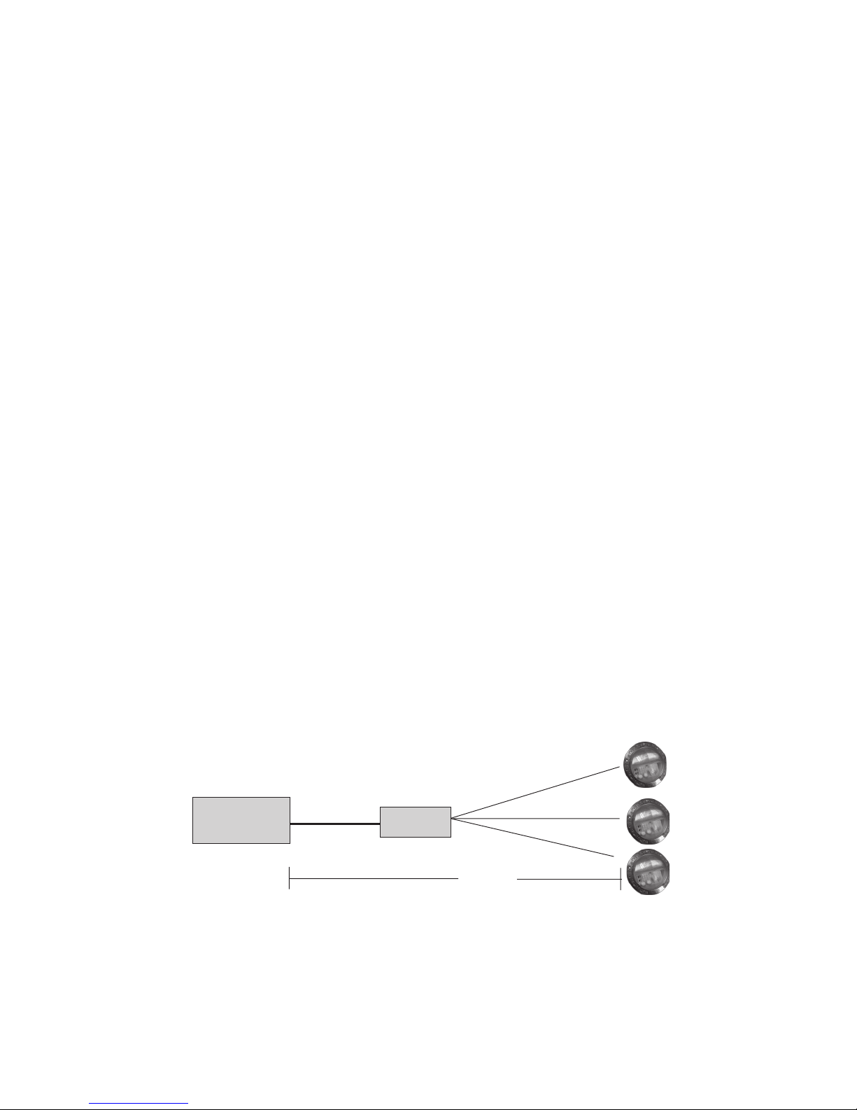
Using an External Transformer for Multiple IntelliBrite 12 VAC Lights
When using multiple IntelliBrite 12 VAC LED lights on a 300 Watt transformer, it is
recommended that no more than three (3) IntelliBrite pool lights and one (1) IntelliBrite
Spa light be used. It is also recommended not to exceed 100 feet of total cable run
between the transformer and light (see diagram below).
300 Watt
Transformer
12 Gauge
(minimum)
J Box
100 ft.
IntelliBrite® 5g Pool LED Light Installation and User’s Guide

2
Operating IntelliBrite Pool LED Lights
Using a Wall Switch
IntelliBrite 5g pool LED lights can be controlled using a standard wall-mount light
switch. Multiple IntelliBrite LED lights can be connected via a junction box to a
single switch so that all lights can be switched on and off together. IntelliBrite 5g
lights are controlled by cycling AC power from a standard wall switch. By turning
the switch on and off a specific number of times, the light activates one of the
seven light show modes, fixed colors, and enables the “Hold” and “Recall” feature.
Selecting a light show mode or fixed color
Switch power on to the light. A white light will momentarily illuminate, followed by
the previously selected color. To select a color show mode (1-7) or fixed color
(8-12), turn the wall switch off/on a specific number of times. Each number (1-12)
shown below corresponds to the number of times to power-cycle the switch to
activate a color light show or fixed color. For details about saving color effects
while in “show” modes, see “Hold” and “Recall” feature
on page 4.
1. SAm Mode: Cycles through white, magenta, blue and green colors
(emulates the Pentair SAm® light).
2. Party Mode: Rapid color changing building energy and excitement.
3. Romance Mode: Slow color transitions creating a mesmerizing and
calming effect.
4. Caribbean Mode: Transitions between a variety of blues and
greens.
5. American Mode: Patriotic red, white and blue transition.
6. California Sunset Mode: Dramatic transitions of orange, red and
magenta tones.
7. Royal Mode: Richer, deeper color tones.
8. Blue: Fixed color.
9. Green: Fixed color.
10. Red: Fixed color.
11. White: Fixed color.
12. Magenta: Fixed color.
13. Hold: Save the current color effect during a color light show.
14. Recall: Activate the last saved color effect.
IntelliBrite® 5g Pool LED Light Installation and User’s Guide
Example: To select California Sunset Mode; turn the
switch off and on six successive times.
▼
3
▼
Tu rn
switch
Off/On
six times
▼
During the off/on
switching process, no
illumination will occur,
then a white light will
momentarily illuminate.
▼
Followed by the
selected
“California
Sunset Mode”
During the off/on switching process, before the selected color is
displayed, no illumination will occur. This operating mode is normal
during the switching process. During this period the pool and spa
will be dark and precautions should be taken to avoid unforeseen
accidents. Failure to observe this warning may result in serious
injury or death to pool and spa users.
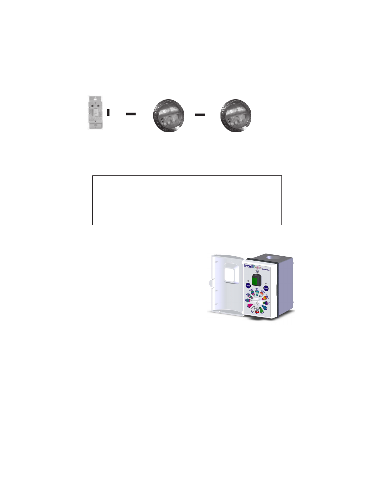
IntelliBrite® Controller (optional)
Instead of using a wall switch, the
IntelliBrite 5g pool LED light can be used
with an IntelliBrite Controller (sold
separately). The IntelliBrite Controller [P/N
600054] provides complete control of
Pentair Water Pool and Spa IntelliBrite
underwater LED (light-emitting diode)
lights, and IntelliBrite LED landscape
lights. It’s easy to select a lighting feature,
just dial in any one of the pre-programmed
color light shows or fixed colors. Using the
Hold and Recall buttons you can also
create endless unique lighting effects. The
IntelliBrite Controller can control individual or multiple IntelliBrite LED lights.
Multiple IntelliBrite LED lights can be connected via a junction box to an
IntelliBrite Controller so that all lights can be switched on and off together.
When using multiple IntelliBrite LED lights, the total allowable light wattage is
300 Watts maximum. The following example combination of IntelliBrite LED
lights can be connected to the IntelliBrite Controller:
• Two (2) IntelliBrite 5g pool LED lights (each light 50 Watt maximum) or two (2)
IntelliBrite pool LED lights (each light 70 Watt maximum)
• One (1) IntelliBrite spa LED light (each light 40 Watt maximum)
• Eight (8) IntelliBrite landscape LED lights (each light 15 Watt maximum)
IntelliBrite® 5g Pool LED Light Installation and User’s Guide

4
Operating IntelliBrite Pool Lights using a wall switch (Continued)
Saving a color mode or fixed color
When power is switched off to the IntelliBrite lights, the last color show mode or
fixed color will be saved. The next time the light is powered on, the previously
saved color show mode or fixed color will be displayed. For example, while in
“Party Mode” switch the light off. Wait more than 10 seconds, switch the light back
on to resume “Party Mode.”
Hold and Recall feature
Hold: Use the Hold feature (power-cycle 13 times) to capture and save a
color effect while displaying one of the light show modes. It’s easier to
capture custom color effects from one of the slower light show modes,
such as “Romance Mode” (#3).
On
▼
▼
▼
Off
▼
Capture a unique color
effect while “Romance
Mode” is active.
Turn switch off/on 13
times to save color
effect.
Saved color effect
is displayed.
Recall: Use the Recall feature to activate the last saved color effect
(using the Hold feature) while in color show mode or fixed colors. To recall
the color effect, power-cycle 14 times, and after five seconds the last
saved color effect will be displayed.
On
▼
▼
While the light is on in
color show or fixed
mode.
IntelliBrite® 5g Pool LED Light Installation and User’s Guide
Turn switch off/on 14
times to activate last
save color effect.
▼
Off
▼
Saved color effect
is displayed.

Powering on the light
When the IntelliBrite LED light is powered on, a momentarily white light will
illuminate, followed by the previously selected color.
Note: If power to the light is off for more than five seconds, the last color show
mode or fixed color that was saved will be displayed.
Troubleshooting
Use the following tips to help to resolve problems that might occur while
operating the LED light.
melborPnoitcA/esuaC
5
.etanimullitonlliwthgilehT
.ylreporpnoitcnuftonseodthgiL
.hctiwsrewopCAehtotdna
.yrassecenfiteserdnagniriwtluafdnuorgehtkcehC
edisloopehttaxobnoitcnujehtotnoitcennocgniriwthgilehtkcehC
.thg
ilehtotdeilpparewopCAreporpsierehttahteruseB
IntelliBrite® 5g Pool LED Light Installation and User’s Guide

6
INTELLIBRITE 5g POOL LED LIGHT FIXTURE INSTALLATION
(NEW POOL CONSTRUCTION)
The following describes how to install the IntelliBrite 5g pool LED light fixture. Read
through pages 6 through 8 before starting the installation procedure.
BEFORE STARTING: The following information describes the tasks that must be
completed by the electrician before the IntelliBrite light fixture is installed in a new
pool construction.
Be sure that the pool or spa meets the requirements of the current National Electrical
Code (N.E.C.) Article 680-22 and all local codes and ordinances. A licensed or
certified electrician must install the electrical system to meet or exceed those
requirements before the underwater light is installed. Some of the requirements of
the National Electrical Code which the pool’s electrical system must meet are as
follows:
• The lighting circuit has a Ground Fault Circuit Interrupter (GFCI) for
line voltage models, and has an appropriately rated circuit breaker.
• The Junction Box (or, for 12 volt models, the low voltage
transformer) is located at least 8 inches above the maximum water
level of the pool and at least 48 inches from the edge of the pool;
see Figure 1.
• The light fixture and all metal items within 5 feet of the pool are
properly electrically bonded.
• The wet niche is properly installed so that the top edge of the
underwater light’s lens is at least 18 inches below the surface of
the water in the pool; see Figure 1. (Not more than 20" depth in
Canada.)
• The wet niche is properly electrically bonded and grounded via the
No. 8 AWG ground connector located at the rear of the niche; see
Figure 1, page 7.
Note: The pool or spa electrical system can be verified with a Pool and Spa Electrical
Qualification Test Kit. The test kit is available from Pentair Water Pool and Spa®. The
electrical system inspection using this kit must be performed by trained and certified
personnel.
•. To be certain that the pool or spa electrical system meets all applicable
requirements, the electrician should also consult the local building
department.
• Use only Pentair Water Pool and Spa wet niches to insure proper
bonding and grounding connections.
IntelliBrite® 5g Pool LED Light Installation and User’s Guide

INSTALLING THE INTELLIBRITE 5G POOL LED LIGHT FIXTURE
(AFTER ELECTRICAL REQUIREMENTS ARE MET)
7
Figure 1.
IntelliBrite® 5g Pool LED Light Installation and User’s Guide

8
INSTALLING THE INTELLIBRITE 5G POOL LED LIGHT FIXTURE
(AFTER ELECTRICAL REQUIREMENTS ARE MET) (CONTINUED)
ite light (after electrical requirements are met)
1. Feed cord through conduit to Junction Box, leaving at least four (4)
feet of cord at the light fixture to coil around the light; see Figure 1, on
page 7. The four (4) feet of cord around the light allows the light to be
serviced after the pool is filled with water.
2. Cut the cord at the Junction Box, leaving at least six (6) inches of
cord to make connections.
3. Strip back six (6) inches of the outer cord jacket to expose the three
insulated wires (be careful not to damage the insulation on the three
(3) inner wires).
4. Connect all three (3) wires to the corresponding circuit wires in the
Junction Box and secure the Junction Box cover in place.
If the light is not submerged in water and powered on for
more than 10 minutes, the light will switch off for a cooling down period of
10 minutes then power back on. This circuitry protects the light from being
potential damage.
5. Install the IntelliBrite light assembly into the niche
and tighten the special bronze pilot screw (see
Pilot screw
(brass)
Figure 1, on page 7.
Use only the special pilot screw
provided with this underwater light. This screw mounts
and electrically grounds the housing securely to the
mounting ring and wet niche. Failure to use the screw
provided could create an electrical hazard which could
result in death or serious injury to pool users, installers or
others due to electrical shock.
6. Fill the pool until the underwater light is completely submerged in
water before operating the light for more than ten (10) seconds.
7. Final check for proper light operation: To check for proper
operation, switch on the main switch or circuit breaker, and the switch
that operates the IntelliBrite underwater light itself. The light should
illuminate when power is applied. If not recheck the installation steps
starting with Step 1.
IntelliBrite® 5g Pool LED Light Installation and User’s Guide

REPLACING THE INTELLIBRITE 5G POOL LED LIGHT ASSEMBLY
(IN AN EXISTING POOL)
Risk of Electrical Shock or Electrocution!
This underwater light must be installed by a licensed or certified
electrician or a qualified pool professional in accordance with
the National Electrical Code and all applicable local codes and
ordinances. Improper installation will create an electrical hazard
which could result in death or serious injury to pool users,
installers or others due to electrical shock, and may also cause
damage to property.
Always disconnect the power to the pool light at the circuit
breaker before servicing the light. Failure to do so could result in
death or serious injury to serviceman, pool users or others due
to electrical shock.
Verify that the pool and spa meets the requirements of the current National
Electrical Code and all local codes and ordinances. A licensed or certified
electrician must install the electrical system to meet or exceed those
requirements before the underwater light is installed. Some of the requirements
of the National Electrical Code which the pool’s electrical system must meet are
as follows:
• The lighting circuit has a Ground Fault Circuit Interrupter (GFCI) for line
voltage models, and has an appropriately rated circuit breaker.
• The Junction Box (or, for 12 volt models, the low voltage transformer) is
located at least eight (8) inches
above ground level and at least 48 inches from the edge of the pool; see
Figure 1 on page 7.
• The light fixture and all metal items within five (5) feet of the pool are
properly electrically bonded.
• The wet niche is properly installed so that the top edge of the underwater
light’s lens is at least 18 inches below the surface of the water in the pool;
see Figure 1 on page 7.
• The wet niche is properly electrically bonded and grounded via the No.
8 AWG ground connector located at the rear of the niche; see Figure 1.
Note: The pool and spa electrical system can be verified with a Pool and
Spa Electrical Qualification Test Kit. The test kit is available from Pentair
Water Pool and Spa. The electrical system inspection using this kit must be
performed by trained and certified personnel.
•. To be certain that the pool’s electrical system meets all applicable
requirements, the electrician should also consult the local building
department.
®
• Use only Pentair Pool Products
and grounding connections.
wet niches to insure proper bonding
9
IntelliBrite® 5g Pool LED Light Installation and User’s Guide

10
REPLACING THE INTELLIBRITE 5G POOL LED LIGHT FIXTURE
(AFTER ELECTRICAL REQUIREMENTS ARE MET)
The following installation instructions describe how to replace the IntelliBrite 5g
Pool LED light fixture from an existing pool.
Failure to bring the pool or spa’s electrical system up to code requirements
before installing the underwater light will create an electrical hazard which
could result in death or serious injury to pool users, installers, or others due to
electrical shock, and may also cause damage to property.
1. WARNING! Switch off main electrical switch or circuit breaker,
and the switch which operates the IntelliBrite underwater light.
2. To remove the IntelliBrite light fixture assembly from the pool
niche: Remove the special bronze pilot screw at top of face ring.
Remove the light assembly from the niche and place it on the deck.
Be sure to keep the special pilot screw from this
underwater light. This screw mounts and electrically
grounds the housing securely to the mounting ring and wet niche.
Failure to use the screw provided could create an electrical hazard
which could result in death or serious injury to pool users, installers or
others due to electrical shock.
3. With the light assembly on the pool deck, cut the light cord leaving at
least size (6) inches of cord to connect to the cord on the replacement
light. Discard the light assembly.
4. Pull the existing cord out of the nich up onto the deck. Strip six (6)
inches of the outer cord jacket from the cord to expose the three
insulated wires.
5. Using electrical insulating tape, wrap each of the three existing light
wires to the cord on the replacement light. Don’t wrap too much tape
around the cords, this will not allow the cord to be pulled through the
conduit to the junction box.
6. Remove Junction Box cover, disconnect the IntelliBrite light fixture
wires and pull the cord through the conduit until the new light cord is
visible in the junction box conduit. Remove the tape wrapped around
the cords and separate the wires.
7. Strip back six (6) inches of the outer new light cord jacket to expose
the three insulated wires (be careful not to damage the insulation on
the three (3) inner wires).
8. Connect all three (3) wires to the corresponding circuit wires in the
Junction Box and secure the Junction Box cover in place.
IntelliBrite® 5g Pool LED Light Installation and User’s Guide

9. Leave at least four (4) feet of cord to coil around the new IntelliBrite
light fixture (see Figure 1 on page 7). This four (4) feet of cord coiled
around the light allows the light to be serviced.
10. Install the IntelliBrite 5g light assembly into the niche in the pool.
11. Install the special bronze pilot screw at the top of face ring to secure
the light to the niche.
12. Final check for proper IntelliBrite light operation: Switch on the
main switch or circuit breaker to the system, and the switch that
operates the IntelliBrite underwater light itself. The light should
illuminate when power is applied. If not recheck the installation steps
starting with Step 1 (page 10).
REPLACING THE INTELLIBRITE 5G POOL LED CIRCUIT BOARD
(IN AN EXISTING POOL)
When replacing or reassembling the IntelliBrite 5g Pool Light,
the Gasket (P/N 79101600) or Gasket and Lens (619864) MUST
ALSO BE REPLACED - SEE PAGE 17 FOR PART NUMBERS
D A N G E R !
RISK OF ELECTRICAL SHOCK OR ELECTROCUTION
Always disconnect power to the pool light at the circuit
breaker before servicing the light. Failure to do so could
result in death or serious injury to installer, serviceman, pool
users, or others due to electrical shock.
Removal and Installation
1. Turn off main electrical switch or circuit breaker, as well as the switch
which operates the IntelliBrite 5g pool LED underwater light itself.
2. Before starting make sure that you have a new lens gasket (P/N 79101600)
and a IntelliBrite 5g pool LED light assembly (P/N 619818Z) ready to install.
11
damage the LED light assembly and may cause an electrical hazard resulting in
death or serious injury to pool users, installers, or others due to electrical shock,
and may also cause damage to property.
Always install a new lens gasket (P/N 79101600) whenever
disassembling the IntelliBrite 5g light assembly. Failure to do so
may permit water to leak into the assembly which could cause:
(a) an electrical hazard resulting in death or serious injury to pool users,
installers, or others due to electrical shock, or
(b) breakage of the lens, which likewise could result in serious injury to pool
users, installers, or bystanders, or in damage to property.
Replace the light assembly with the same type and wattage.
Failure to replace the light assembly with the same type will
IntelliBrite® 5g Pool LED Light Installation and User’s Guide
12
REPLACING THE INTELLIBRITE 5G POOL LED LIGHT ASSEMBLY
(IN AN EXISTING POOL) (Continued)
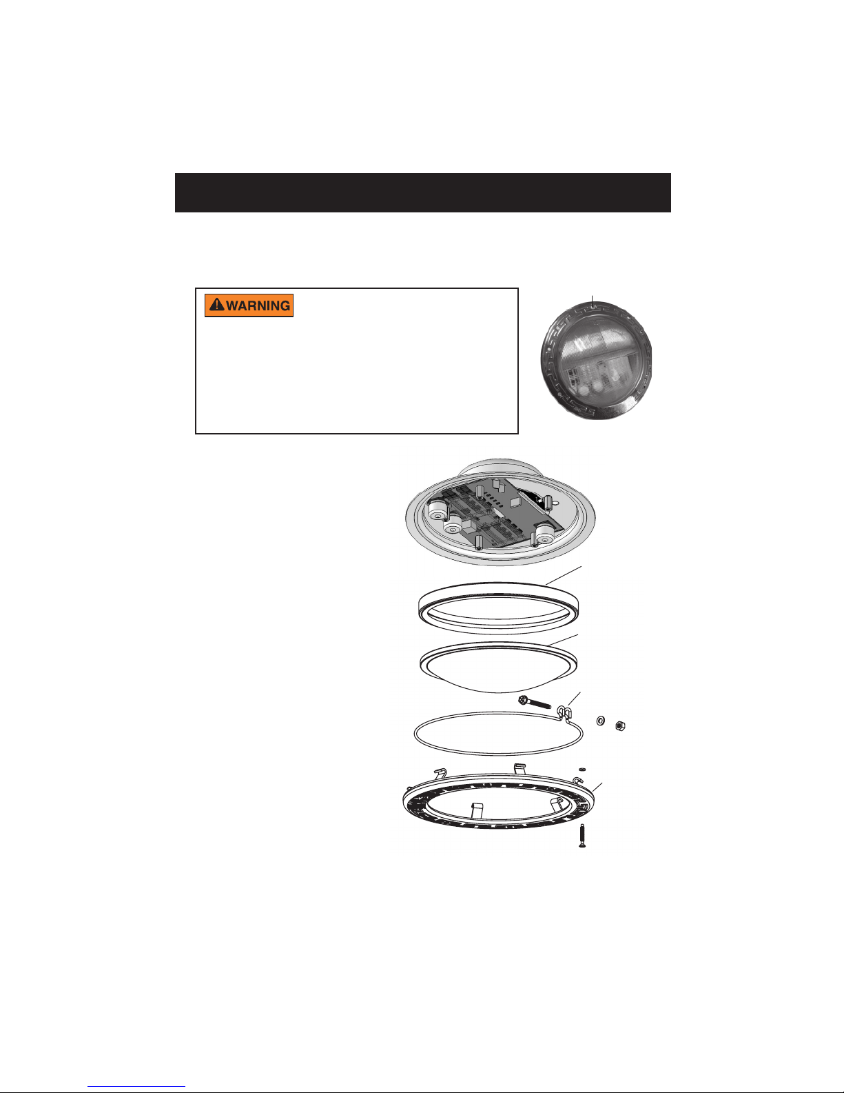
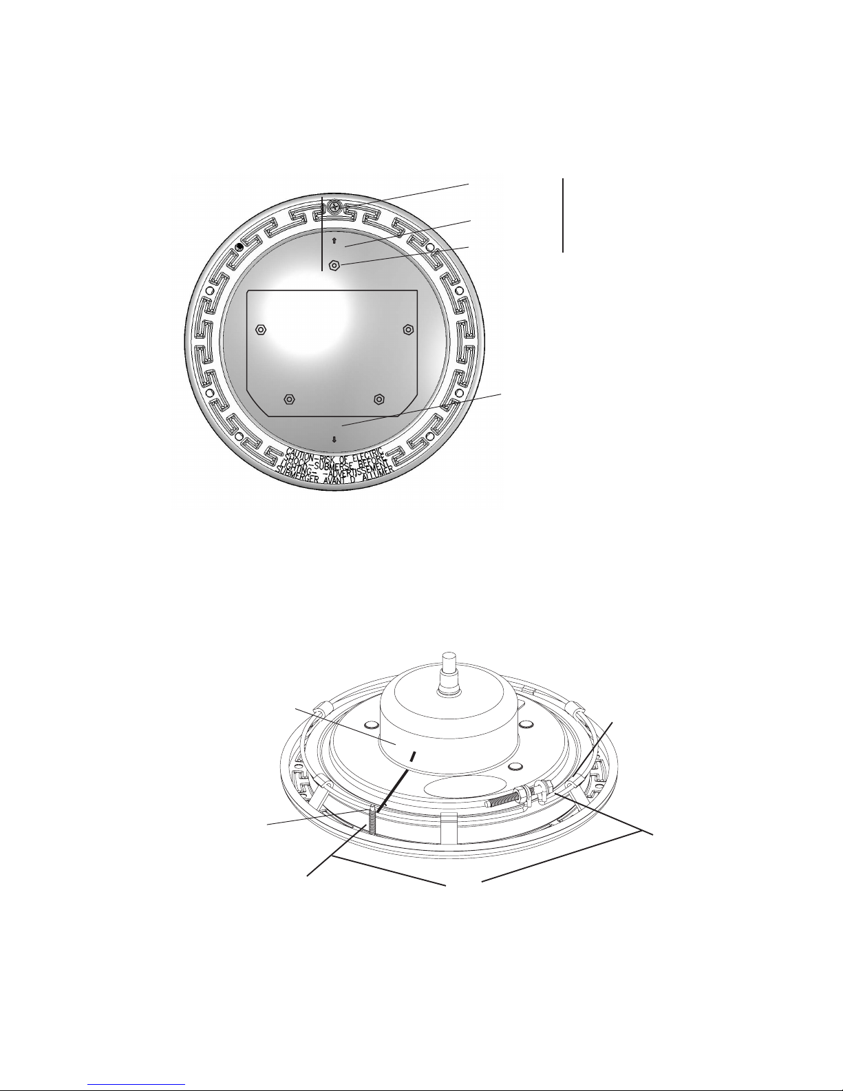
3. REMOVING THE 5g INTELLIBRITE LED LIGHT: Remove the pilot screw at
top of face ring, remove the light assembly from the niche. Place the
assembly on the deck. Note: It is not necessary to drain down the pool.
Pilot screw (brass)
Be sure to keep the pilot screw
from the IntelliBrite 5g LED underwater light. This
screw mounts and electrically grounds the housing
securely to the mounting ring and wet niche. Failure
to use the screw provided could create an electrical
hazard which could result in death or serious injury
to pool users, installers or others due to electrical
shock.
4. Place a cloth on the ground
to protect the lens. Turn the
light over so the lens is
resting on the cloth. Using a
¼" nut driver and a #3
Phillips screwdriver, remove
the nut uni-tension wire
clamp. Place the nut aside
for reinstallation.
5. Remove the face ring
and wire clamp from the
light housing.
6. With the light resting on
its base, carefully pry off
the gasket to remove the
lens. Set the lens aside
for installation later.
Discard the gasket.
Note: A NEW LENS
GASKET
(P/N 79101600) MUST
BE USED EACH TIME
THE LIGHT IS
REASSEMBLED.
See page 18 for
Replacement Kit part
numbers.
Gasket
Lens
uni-tension
wire clamp:
Remove nut
and screw
Face ring
Note: Note the current position of the lens at the pilot screw (12 o’clock)
position, before removing it from the fixture. “W” on the lens indicates wide
angle, “N” indicates narrow angle. For more information, see page 17.
IntelliBrite® 5g Pool LED Light Installation and User’s Guide
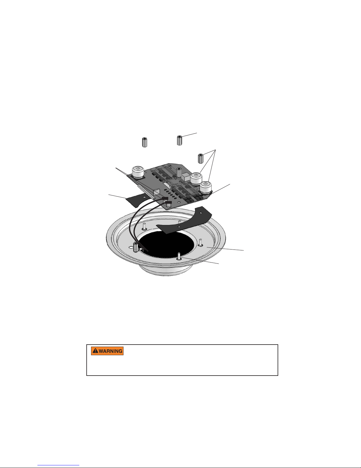
7. Using a ¼" nut driver, carefully remove the four retainer nuts from the LED
light assembly.
driver while removing the studs.
NOTE: Be sure not to damage the capacitors with the nut
Place the nuts aside for reinstallation.
8. Unplug the two connector plugs from the circuit board. Lift up the circuit
board and remove it from the light housing base.
9. Carefully lift off the thermal strips from the base of the light housing base.
Proceed with installation step 10 on page 14.
Retaining nut (4x)
Note: Be careful not to
damage capacitors
Circuit board
when removing nut.
connector plugs
5g Light circuit
board assembly
Thermal
strip (2x)
PAGE 13-14
13
Light housing
Circuit board
stud (4x)
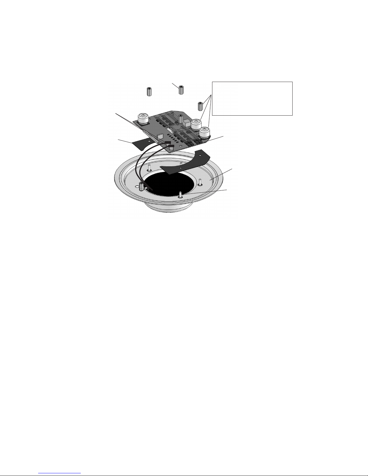
INSTALLING THE INTELLIBRITE 5g POOL LED LIGHT ASSEMBLY
WITH NEW GASKET (see illustration on next page)
10. Place the two thermal strips (provided) over the circuit board studs in the
base of the light housing (see illustration on next page)..
11. Place the light circuit board over the base studs and seat the circuit board
on top of the thermal strips. Be sure the two connecting wires are not
caught between the housing and the edge of the circuit board.
12. Using a ¼" nut driver, secure the circuit board with the four (4) retaining nuts.
Be sure to install ALL of the four (4) retaining nuts. These
nuts ensure proper electrical ground. Failure to install all of the retaining
nuts could create an electrical hazard which could result in death or serious
injury to pool users, installers or others due to electrical shock.
13. Connect the two connector plugs to the circuit board terminals.
Continue on next page.
IntelliBrite® 5g Pool LED Light Installation and User’s Guide
14
Retaining nut (4x)
WARNING! Be sure to install
ALL four nuts for proper
electrical grounding and safety.
Circuit board
connector plugs
Thermal
strip (2x)
PAGE 13-14
Note: Be careful not to damage
capacitors when installing nut.
5g Light circuit
board assembly
Light housing
Circuit board
stud (4x)
14. Install NEW GASKET ONTO LENS (see illustration on next page): Stretch
the gasket around the circumference of the lens. Be sure the gasket is
installed evenly around the lens.
15. ALIGN LENS/GASKET ONTO LIGHT HOUSING:
a) With the light housing resting on its base, place the lens/gasket on top of
the light housing.
b) Rotate the lens/gasket to align the letter “W” (“WIDE” angle) on the lens
with the brass nut in the housing (see diagram on page 15 for brass nut
location).
Note: The IntelliBrite 5g light lens ships from the factory in the ‘WIDE’ (W) angle
position. To use the “NARROW” angle light beam, rotate the lens/gasket to
align the letter “N” on lens. Note: For more information about using the “WIDE”
and NARROW angle lens, see page 17.
16. INSTALL FACE RING: Place the face ring on top of the lens/gasket/housing.
Rotate the face ring so the
pilot screw
hole is aligned in the 12 O’clock
position, with the lens letter “W” (or “N”) and the brass nut in the housing. Also,
verify the “TOP” position arrow indicator label (see page 15) on the rear of the
housing is aligned with the pilot screw on the face ring.
IntelliBrite® 5g Pool LED Light Installation and User’s Guide
15
PILOT SCREW
(12 O’clock)
“W” ON LENS
ALIGN
W
N
17. INSTALL UNI-TENSION CLAMP: With the hook ends of the circular uni-tension
clamp pointing down, spread the clamp and place it in the “U” recesses of the
locking levers. Be sure the hook ends of the clamp are located between the pair
of locking levers as shown below and that the wire clamp is properly engaged
with all of the lock levers.
18. Place a cloth on the ground to protect the lens. Turn the light over so the lens is
resting on the cloth. Be sure the orientation of the wire clamp and the bolt
connection is positioned at 45°.
19. Tighten the bolt and nut until the distance between the ends of the clamp equals
¼-inch or less. Continue with Step 20 on the next page.
BRASS NUT
Align letter “W” (“WIDE”
angle) on lens/gasket with
pilot screw hole
and
brass nut
For “NARROW” angle light
beam, rotate “N” to 12
O’clock position
ALIGN
on face ring
“TOP” label
(use to align light
housing with pilot
screw on face ring
PILOT
SCREW
Lock
lever
TOP
▼
45°
Position the wire clamp (nut and bolt) about 45°
between the PILOT SCREW and LOCK LEVER.
IntelliBrite® 5g Pool LED Light Installation and User’s Guide
16
20. Install the special bronze pilot screw at the top of face ring to secure
the light to the niche.
Pilot screw (brass)
21. Final check for proper IntelliBrite light operation: Switch on the
main switch or circuit breaker to the system, and the switch that
operates the IntelliBrite underwater light itself. The light should
illuminate when power is applied. If not recheck the installation steps
starting with Step 1 (page 11).
IntelliBrite® 5g Pool LED Light Installation and User’s Guide
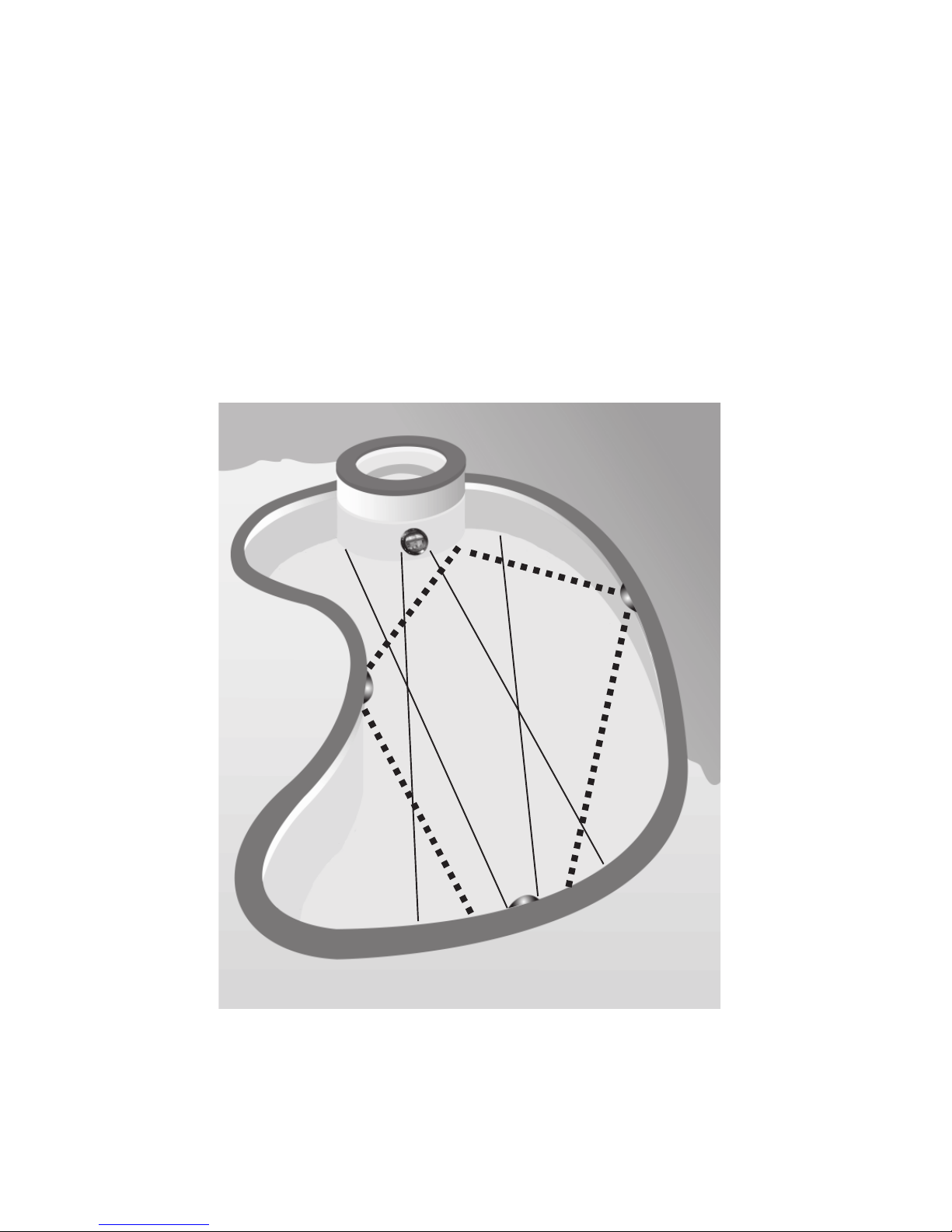
Wide and Narrow Angle Lens Adjustment
Unique Wide and Narrow Angle Lens Feature
The unique IntelliBrite 5g LED pool light lens geometry provides a choice of “wide” or
“narrow” angle light beam to suit various size pools. For lights located on either side of
the pool, simply rotate the lens to the ‘wide’ (W) angle position, which will provide a wider
angle light beam for greater underwater coverage and light reflection. For lights located
either end of the pool, rotate the lens to the ‘narrow’ (N) angle light beam position for
increased underwater light intensity and distance.
Note: The IntelliBrite 5g light lens ships from the factory in the ‘WIDE’ (W) angle position.
NARROW ANGLE
LIGHT BEAM
WIDE ANGLE
LIGHT BEAM
17
WIDE ANGLE
LIGHT BEAM
NARROW ANGLE
LIGHT BEAM
Recommended IntelliBrite 5g ‘Wide’ and ‘Narrow’ angle Lens Position
IntelliBrite® 5g Pool LED Light Installation and User’s Guide

18
IntelliBrite 5g Pool LED Light Assembly
Replacement Kit Part Numbers
1
2
3
4
5
6
7
Note: A 120 VAC to 12 VAC external
transformer is required for the 12 VAC
model IntelliBrite 5g Pool light.
See page 1 for more information.
Item No. Kit Part No. Description
2, 3, 5 600095 Face Ring assembly, stainless steel.
- Uni-tension wire clamp assembly.
- Gasket, 8-3/8 in. diameter, off white.
4, 5 619864Z Replacement Lens Kit.
- Gasket, 8-3/8 in. diameter, off white.
- Lens, IntelliBrite 5g, Pool, 8-3/8 in. diameter, tempered.
3, 5, 7 619818Z (UL), 619905Z (CSA) - Replacement Kit.
(Circuit Board and Thermal Strips (2x), 5g Pool light assy.)
- Uni-tension wire clamp assembly.
- Gasket, 8-3/8 in. diameter, off white.
1 79104800 Pilot screw, with captive gum washer.
5 79101600 Gasket, 8-3/8 in. diameter, off white.
Note: The 120 VAC IntelliBrite 5g pool LED light has an integrated 12 VAC transformer.
IntelliBrite® 5g Pool LED Light Installation and User’s Guide

Notes
19
IntelliBrite® 5g Pool LED Light Installation and User’s Guide

*619827*
P/N 619827 Rev C
IntelliBrite® 5g Pool LED Light Installation and User’s Guide
 Loading...