

Pentair Everpure 804-023 Installation Manual
WATER BOOST SYSTEM
PUMP SPECS (8025-934-399)
Motor Design 115 VAC 60 Hz permanent magnet; thermally protected and a non-replaceable integral fuse
Duty Cycle
Turn-On/Off Pressure 70 PSI [4.8 bar] / 90 PSI [6.2 bar]
Max. inlet pressure
Check Valve
Temp. Limits
Pump materials
Port / Fitting
TANK SPECS
Total Volume (air/liquid)
*Approx. Draw Down Vol. 123 Oz. [3.6 lt.]
Bladder Material:
Housing Material
Temp. Limits
Max. Working Pressure
Port
Intermittent (max. run time 20 min. within one hour)
30 psi [2 bar]
Internal (prevent reverse flow)
34 º - 120 º F [1.1 º - 49 º C]
EPDM valves, Santoprene diaphragm, Nylon housing
QD ports female / 3/8" barb fittings
2 gal [7.6 lt]
Butyl
Stainless Steel
34 º - 120 º F [1.1 º - 49 º C]
117 psi [8 bar]
1/2" NPT Female
* Draw down volume varies with tank pre-charge, pump operating pressure and city water pressure. Specs
reflect tests at 40 psi [2.7 bar] pre-charge w/20 psi [1.3 bar] city water pressure.
WATER BOOST SYSTEM LIMITED WARRANTY
SHURflo Water Boost Systems are warranted to be free of defects in material and workmanship under normal
use, for a period of one (1) year from the date of manufacture, or one (1) year of use, with proof of purchase.
This limited warranty will not exceed two (2) years, in any event.
The limited warranty will not apply to Water Boost Systems that were improperly installed, misapplied, or
incompatible with fluids or components not manufactured by SHURflo. Water Boost System failure due to
foreign debris is not covered under the terms of this limited warranty. SHURflo will not warrant any Water
Boost System which is damaged or modified outside the SHURflo factory.
Returns are to be shipped postage prepaid to either service center; SHURflo Garden Grove, CA or Elkhart, IN.
SHURflo shall not be liable for freight damage incurred during shipping, package returns carefully.
For complete warranty details consult S/B #1049.
« ISO Certified Facility
SHURflo reserves the right to update specifications, prices, or make substitutions.
SHURflo «
5900 Katella Ave.
Cypress, CA 90630
(800) 854-3218 (562) 795-5200
FAX (562) 795-7564
Shipping/UPS: 5900 Katella Ave., Ste.B
Cypress, CA 90630
SHURflo East
52748 Park Six Court,
Elkhart, IN 46514-5427
((800) 762-8094
(219) 262-0478
FAX (219) 264-2169
© 2002 Printed in USA
Unit 5 Sterling Park, Gatwick Road,
SHURflo Ltd.
Crawley, West Sussex, RH10 2QT
United Kingdom
+44 1293 424000
FAX +44 1293 421880
INSTALLATION AND OPERATION MANUAL
WARNING: “Risk of electrical shock.” The pump is supplied with a grounding connector and grounding-type
attachment plug. To reduce the risk of electrical shock, be certain that it is connected only to a
properly grounded, grounding-type receptacle. To prevent electrical shock, disconnect power
before initiating any work. In the case of pump failure, the motor housing and/or the pumped fluid
may carry high voltage to components normally considered safe.
WARNING: Never pressurize the accumulator tank higher than its maximum operating pressure of 117 psi [8
bar] limit. Never expose the tank to higher than 120ºF [49ºC] ambient temperature environment.
CAUTION: DO NOT adjust the pump pressure switch setting. Switch setting will not significantly alter flow
rate or pressure. Improper adjustment may cause severe overload or premature failure, not covered
under warranty.
CAUTION: DO NOT operate the pump at pressures, which cause the motor to exceed the amperes rating
indicated on the nameplate. The pump is equipped with thermal breakers to interrupt operation
due to excessive heat. Once the temperature of the motor is within proper limits it will
automatically reset, and the pump will start operation without warning. The motor is equipped
with an integral non-serviceable fuse. Pumps which have an “open” fuse are not covered under
the limited warranty.
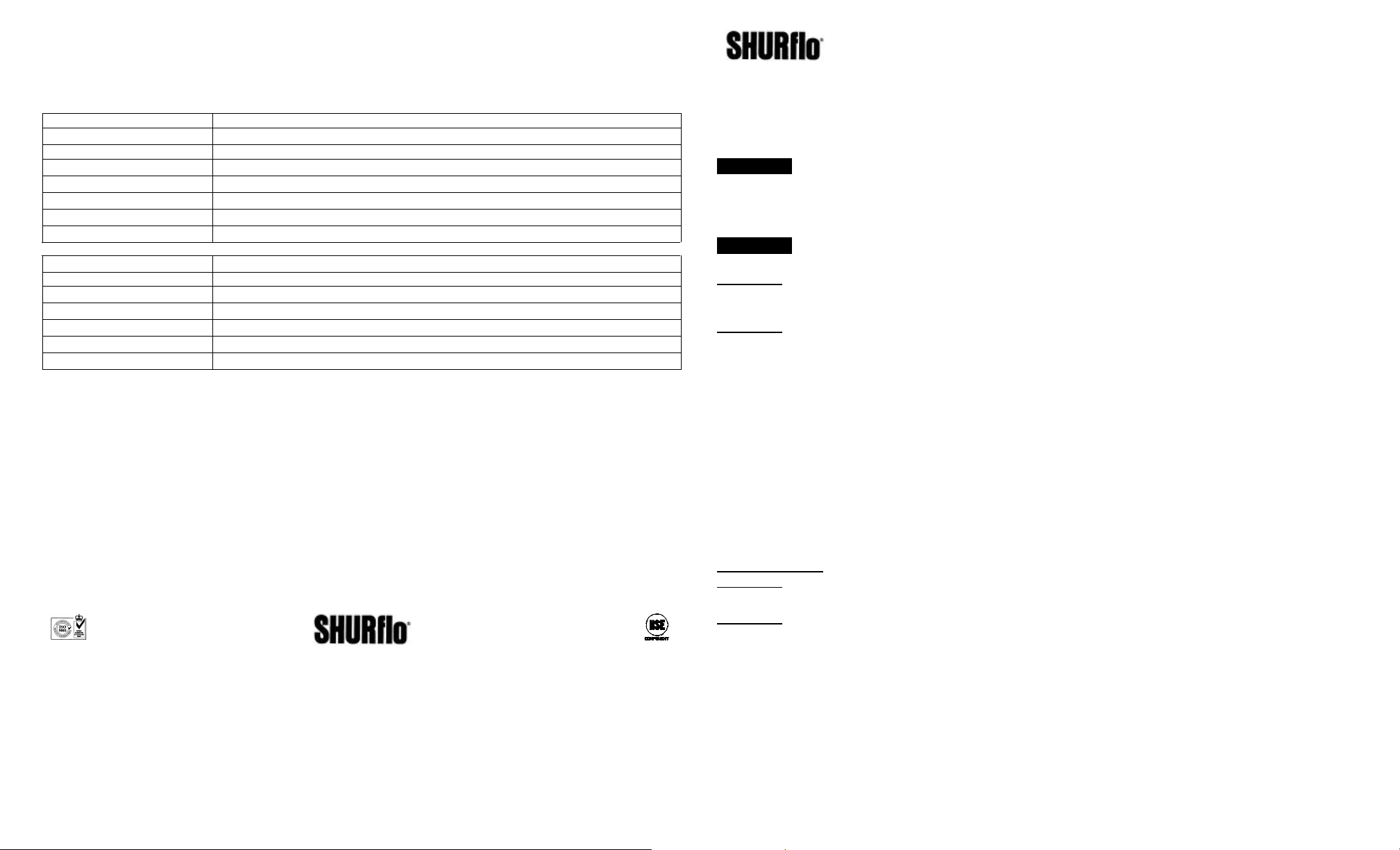
ACCUMULATOR STORAGE/FLOW-RATES
SHURflo Water Boost Systems are for applications when low, fluctuating, or no water pressure exists. The
pump and accumulator maintain consistent water pressure to a source (for a given duration) as long as incoming
water is sufficient. Depending upon the Water Boost System model, support of up to 4 non-carbonated valves in
moderate volume accounts is achievable. The Water Boost Systems may be used to supply water to a carbonator
for back-up, during short periods of insufficient water pressure. The pump pressurizes the accumulator to 90
psi. [6 bar]. Consult the flowchart for projected length of flow and/or back-up. The pump is NSF, UL and C-UL
listed.
INSTALLATION
CAUTION: DO NOT pre-charge the accumulator with CO
2. In the event of failure
carbonated water will react
with brass components in system equipment. Use clean, dry air or nitrogen.
CAUTION: a qualified electrician, in accordance with all local electrical codes should perform all electrical
outlet (receptacle) wiring connections. Circuit protection is dependent on the individual application
requirements. Failure to provide proper circuit protection may result in a motor failure, which is not covered
under warranty.
1. The water booster system is to be installed between the water source and non-carbonated valve(s) or
carbonator (see Installation figure in the following page). Turn off city water supply before installation.
Note 1: Depending upon your application, it is recommended that a SHURflo 50 psi water pressure reducer
valve be installed after the filter system before the line is teed to the carbonator and the non-carb valves.
911-592 Rev. A 4-22-02 4 of 4 911-592 Rev. A 4-22-02 1 of 4
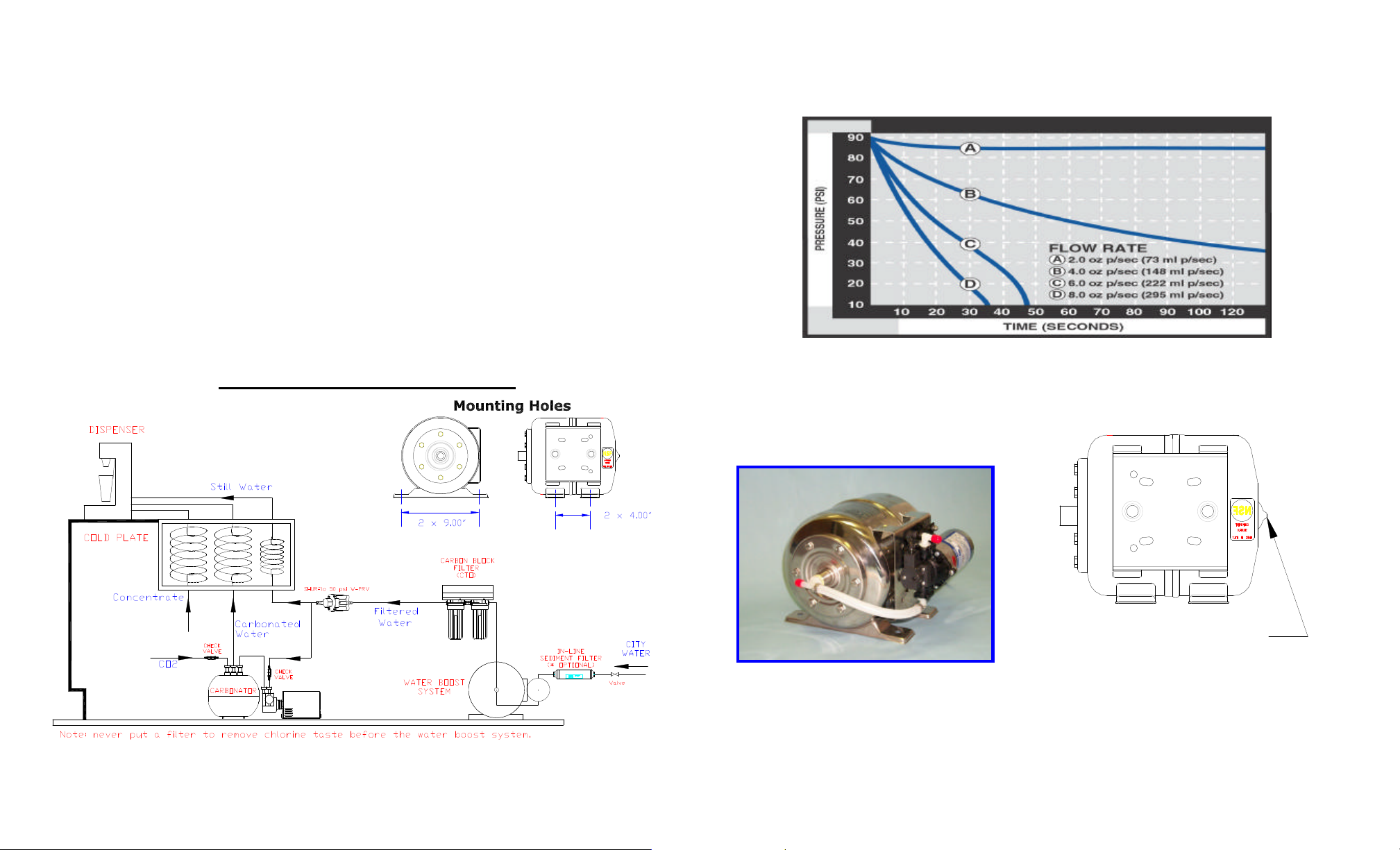
2. Use NSF listed high pressure braided 3/8" ID [9.5 mm] tubing to connect the inlet/outlet ports. Secured all
tubing connections with SS, step-less Oetiker clamps. Cable-tie all tubing securely to prevent kinks or sags
that can inhibit performance or cause damage to the pump.
3. Remove Accumulator air fitting cap and pre-charge with clean pressurized air, or nitrogen. Tank should be
pre-charged at the minimum required pressure of the application. Replace air fitting cap securely. Check
pressure bi-monthly.
4. In most cases 50 psi [3.4 bar] will provide the required pressure at a typical beverage dispense system. For
best pump performance, set accumulator pre-charge pressure at approximately 20 psi [1.3 bar] below max.
pump pressure (as stated on the pump label), and/or at approximately the pump turn-on pressure. For further
information consult the factory.
5. Turn ON incoming water supply.
6. Open the dispenser valves and purge air/water from tubing/accumulator. Close the dispenser valve(s) and let
the pump fill the accumulator. The pump may not obtain shut-off pressure if excessive air is trapped within
the system. Repeat this step 3-5 times as necessary, before taste testing.
NOTE 2: if subject to freezing temperature, the pump, tubing and accumulator tank MUST be drained of all
water.
Water Boost System Installation Diagram
.
WATER BOOST SYSTEM PERFORMANCE (Units tested with 40 psi pre-charge and 20 psi city water pressure)
Remove cap to precharge tank.
Recap after charging tank.
NOTE 3: the accumulator tank pre-charge should be
checked bimonthly or as necessary. All outlet water
pressure must be depleted prior to checking or recharging
2 of 4 3 of 4
 Loading...