

Page 1
X-10 Transmitter and Receiver Instructions
IMPORTANT SAFETY INSTRUCTIONS
READ AND FOLLOW ALL INSTRUCTIONS
SAVE THESE INSTRUCTIONS
Table of Contents
Section I. Installation Instructions..............................................................................2
Section II. Operating Instructions ...............................................................................3
Section III. Troubleshooting ........................................................................................4
Important Notice
Attention Installer.
This manual contains important information about the installation, operation and safe use of this product.
This information should be given to the owner/operator of this equipment. If you have any questions or
need additional free copies of these instructions, please call (800) 831-7133.
Important Notice
This equipment has been tested and found to comply with the limits for a Class B digital device, pursuant to Part 15 of
the FCC Rules. These limits are designed to provide reasonable protection against harmful interference in a residential
installation. This equipment generates, uses and can radiate radio frequency energy and, if not installed and used in
accordance with the instructions, may cause harmful interference to radio communications. However, there is no
guarantee that interference will not occur in a particular installation. If this equipment does cause harmful interference to
radio or television reception, which can be determined by turning the equipment off and on, the user is encouraged to
try to correct the interference by one or more of the following measures:
— Reorient or relocate the receiving antenna.
— Increase the separation between the equipment and receiver.
— Connect the equipment into an outlet on a circuit different from that to which the receiver is connected.
— Consult the dealer or an experienced radio/TV technician for help.
No changes or modifications may be made to the units. Any changes made to the unit will void the user’s authority to
operate the equipment.
Pentair Pool Products
1620 Hawkins Ave., Sanford, NC 27330 • (919) 774-4151
10951 West Los Angeles Ave., Moorpark, CA 93021 • (805) 523-2400
Rev. A 12-5-03 1 P/N 840344
Page 2
Section I. Installation Instructions
A. PG2000 RETROFIT INSTRUCTIONS
Using The X-10 Remote Control
NOTE:
If an X-10 system is present prior to this installation, module settings for this unit must be adjusted to allow for settings already in
use. See operating instructions for directions on how to change manufacturer default settings and then adjust the installation
settings accordingly.
DANGER
Risk of Electrical Shock or Electrocution.
Always disconnect the power to the PG2000 at the circuit breaker before removing the lid and servicing the light.
Failure to do so could result in death or serious injury to serviceman, pool users or others due to electrical shock.
1. Turn power switch and colorwheel switch on the side of the PG2000 unit to their “OFF” positions and disconnect
power at the circuit breaker.
2. Remove the PG2000 cover by removing the bottom
screws.
3. If retrofitting an RF2000 wireless system, locate the
receiver module (on the left side of the unit) and
13
15
.
11
Model
XPFM
1
..
..
9
UNITHOUSE
3
7
disconnect its 4-pin plug from the PG2000. Remove the
receiver module usually held in place by double stick tape.
4. Take one of the XPFM modules (see Figure 1), set the
UNIT dial to channel 2 and the HOUSE dial to the
appropriate code (A is usually chosen for first time X-10
use). Place this module on the LEFT side of the PG2000
as seen in Figure 4. First clean the mounting surface, then
attach module with the double stick tape provided. Using
the wire nuts provided, connect the BLUE wire and the
YELLOW wire (from the colorwheel fuse). The BLACK
(120VAC, line) wire will be connected in the next
instruction.
5. Take the other module, set the UNIT dial to channel 1 and
the HOUSE dial to the same as the other module. Onto a
clean mounting surface, place this module on the RIGHT
side of the PG2000 with the double stick tape provided.
Connect the BLUE wire, the BLACK wire (from the
LEFT side XPFM), and the smaller BLACK wire from
the Ballast fuse together. Now, connect the RIGHT side
XPFM’s BLACK wire to the main’s BLACK wire.
X-10
Fixture Module
A
..
C
..
.
G
..
I
E
Figure 1.
M
O
.
K
..
5
.
6. Connect all the WHITE (neutral) wires together with one wire nut (should be 4 white wires in all).
7. Connect the mains GREEN (chassis) wire and the PG2000’s GREEN wire together with a wire nut.
8. Check that all connections are tight and no bare conductors are exposed. Verify connections with the wiring
diagram in Figure 4.
9. Replace the PG2000 cover and fasten with screws.
10. Change the side switches to match the Remote Switch Control setting (see Figure 3). Each switch is set to its own
remote switch position (power and colorwheel).
P/N 840344 2 Rev. A 12-5-03
Page 3

Section II. Operating Instructions
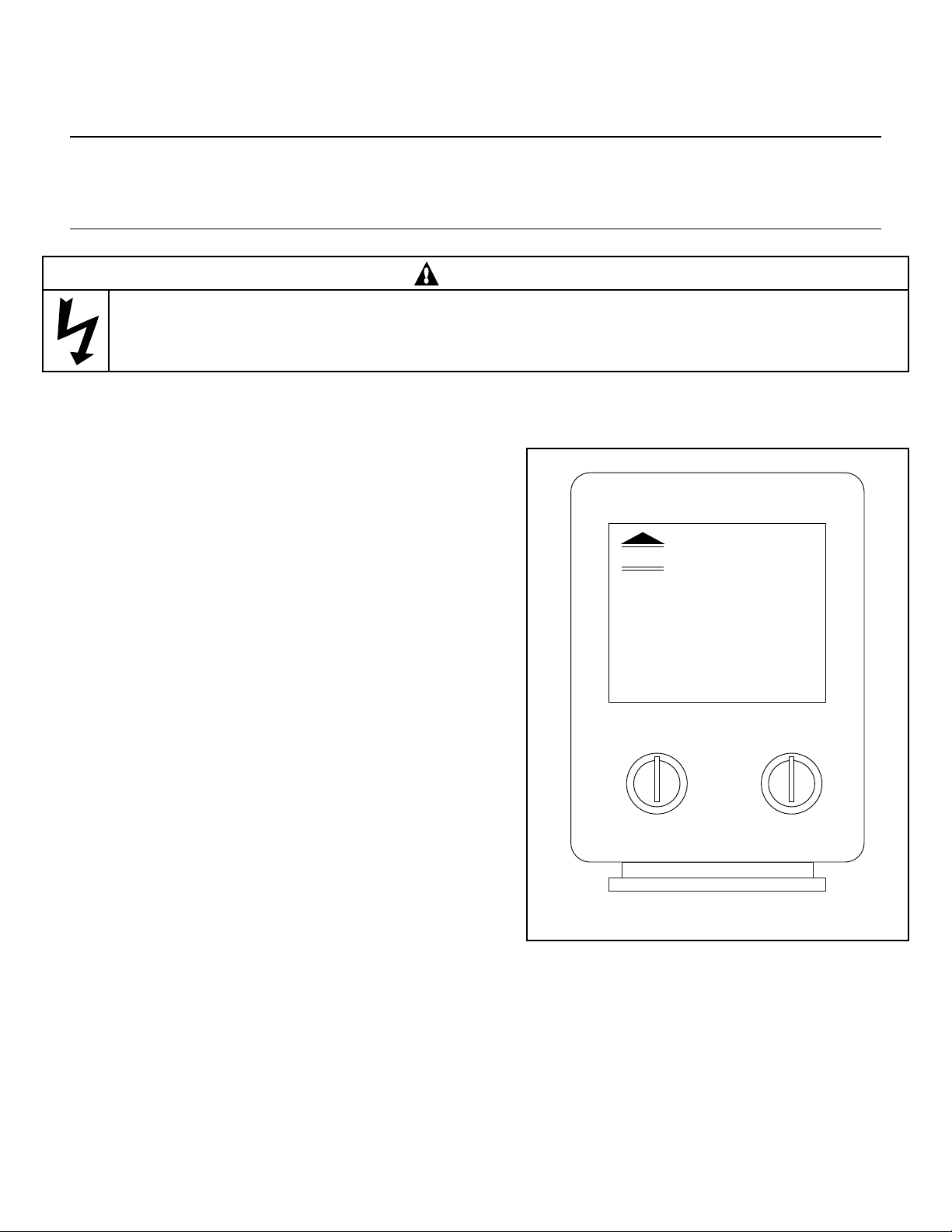
1. Plug in the Transceiver (see Figure 2)
and extend antenna.
NOTE
On
1
Off
The Transceiver is NOT weather-proof and
MUST be installed indoors at least 5 feet from
On
2
Off
the pool or the minimum distance from the
pool that local building codes require.
2. Using the keychain remote (see Figure 2),
press the first (top) ON button to turn on
power for the PG2000 bulb, press the
first (top) OFF button to turn off. Press
the second ON button to start the
colorwheel, press the second OFF button
Keychain Remote
Figure 2.
to stop the colorwheel.
NOTE
Power to the PG2000 must be pressed first before being able to start the colorwheel.
A. To change the HOUSE code:
• Take the keychain remote, press and hold the first (top) ON button. While holding down, the red LED will blink
once, 3 seconds later, the LED will then blink the current setting: 1 blink for HOUSE code A, 2 blinks for B,
…, 16 for HOUSE code P.
• Release the ON Button.
• Press and release the first (top) ON button the number of times for the HOUSE code you want to set: 1 for A,
2 for B, … 16 for P. The LED will blink for each press.
• VERIFY the new setting by holding down the first (top) ON button, the LED will turn on, 3 seconds later, the LED
will then blink the new setting.
X-10
POWERHOUSE
Transceiver
Module
HOUSE
O
M
.
K
..
ON/OFF
A
..
C
..
E
.
G
I
B. To change the UNIT code for the first (top) two buttons: (the second pair of ON/OFF buttons are always one
number higher than the first pair, i.e. if you set the first button to 6, the second button controls 7).
• Press and hold the top OFF button. The red LED will blink
once, 3 seconds later, the LED will then blink the current
setting: 1 blink for UNIT code 1, 2 blinks for 2, …, 16 blinks
for 16.
• Release the top OFF button.
TOGGLE SWITCH POSITIONS
MANUAL CONTROL
• Press and release the top OFF button the number of times
for the UNIT code you want.
• VERIFY the new setting by holding down the top OFF
button, the LED will turn on, 3 seconds later, the LED will
then blink the new setting.
C. To change the battery:
POWER
REMOTE SWITCH CONTROL
OFF
COLOR
OFF
ON
COLOR
ON
POWER
RF2000 WIRELESS CONTROL
• Pry the keychain remote apart and fit a CR2025 Lithium 3V
battery into slot. Observe the polarity.
NOTE
If the unit is cycled off then on it may take up to 3-4 minutes for the
lamp to “restrike” or come back on. All metal halide lamps have
this characteristic and this is a normal function of the PG2000.
POWER
Figure 3.
COLOR
POWER
COLOR
Rev. A 12-5-03 3 P/N 840344
Page 4

Section III. Trouble Shooting
0.5A
PG2000 (Fro nt V ie w ) & Wiring D ia g r am
X
A
O
M
K
C
E
G
I
..
..
.
..
.
HOUSE
9
1
3
5
7
..
..
.
..
.
UNIT
13
1
5
11
X
A
O
M
K
C
E
G
I
..
..
.
..
.
HOUSE
9
1
3
5
7
.
.
..
.
..
.
UNIT
13
15
1
1
“LEFT” “RIGHT”
3A
CHASSIS
NEUTRAL
LINE
PG2000
Chassis GND
PG2000 Neutral
BLACK (Line)
YELLOW
WHITE (Neutral)
BLUE
GREEN (Chassis)
Mains
AC Power
(Colorwheel Fuse) (Ballast Fuse)
If there is a signaling
problem, the following
methods may remedy it:
Problem: Short operating
distance (20 ft. or less).
Action:
• Change battery
(CR2025, 3V Lithium) in
keychain remote.
Problem: Not operating.
Action:
• When using the keychain
remote, make sure you
are within the expected
operating distance from
the Transceiver.
(Operating distances can
very depending on local
RF noise levels.)
• Verify the House and
Unit codes are set
correctly on the
Transceiver, keychain
remote, and the PG2000.
CAUTION
BEFORE removing PG2000
cover, ALWAYS
DISCONNECT POWER at
main breaker AND at the
PG2000 switches. In order to
verify the codes in the
PG2000, the cover must be
removed.
Figure 4.
SAVE THESE INSTRUCTIONS.
Pentair Pool Products
1620 Hawkins Ave., Sanford, NC 27330 • (919) 774-4151
10951 West Los Angeles Ave., Moorpark, CA 93021 • (805) 523-2400
P/N 840344 4 Rev. A 12-5-03
 Loading...