


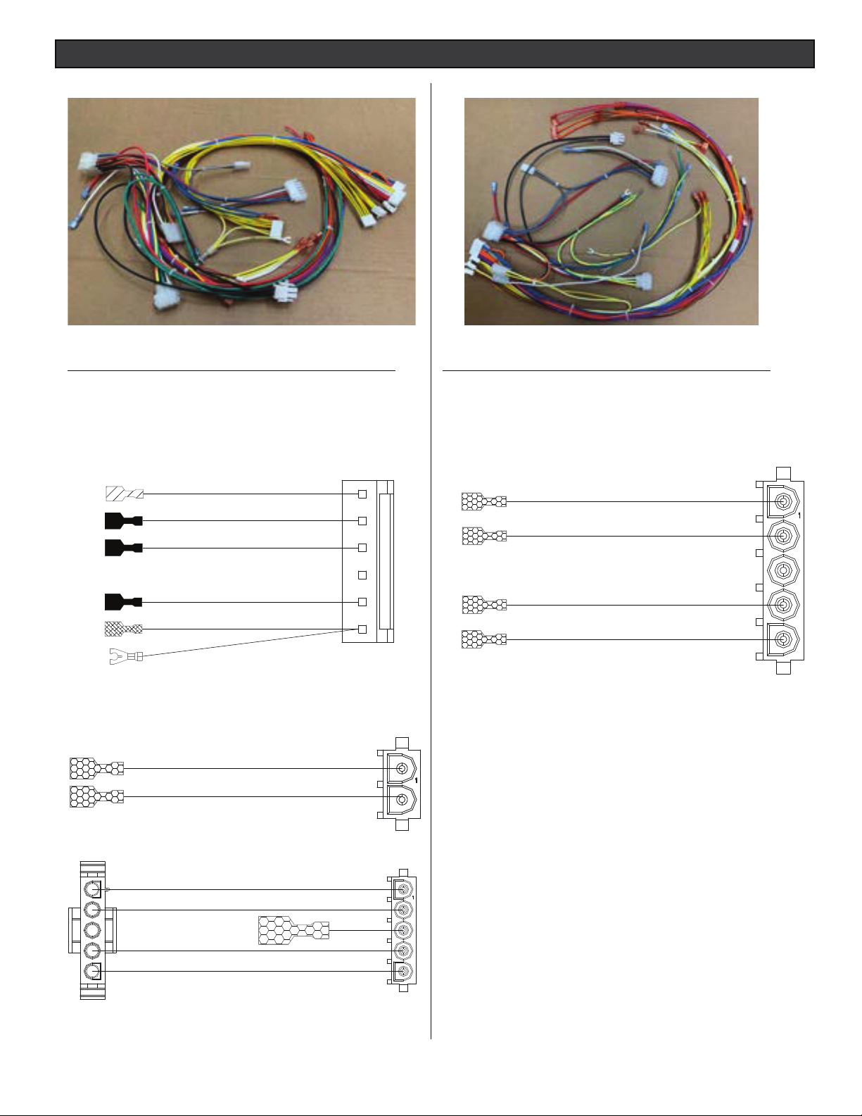
WIRE HARNESS REPLACEMENT KIT
USA (P/N 461107) AND AUSTRALIA (P/N 461108)
FOR MASTERTEMP® AND MAX-E-THERM® POOL AND SPA HEATERS
INSTALLATION INSTRUCTIONS
FAILURE TO FOLLOW ALL INSTRUCTIONS AND WARNINGS CAN RESULT IN
SERIOUS BODILY INJURY OR DEATH. THIS PRODUCT SHOULD BE
INSTALLED AND SERVICED ONLY BY A QUALIFIED POOL SERVICE
PROFESSIONAL. INSTALLERS, POOL OPERATORS AND OWNERS MUST
READ THESE WARNINGS AND ALL INSTRUCTIONS IN THE HEATER
INSTALLATION AND USER’S GUIDE BEFORE USING THIS PRODUCT.
THESE INSTRUCTIONS MUST BE LEFT WITH THE POOL OWNER.
Pentair Water Pool and Spa heater related products are available at:
https://www.pentair.com/en/products/pool-spa-equipment/pool-heaters.html
Call (800) 831-7133 for additional free copies of these instructions.
IMPORTANT SAFETY INSTRUCTIONS
READ AND FOLLOW ALL INSTRUCTIONS - SAVE THESE INSTRUCTIONS
Wire harness Instructions for USA and Australian heater models
The following instructions describe how to replace the wire harness in a MasterTemp or Sta-Rite pool
and spa heater (USA and Australia models) that doesn’t have RS-485 communication capability and
a legacy Ignition Control Module. If you do not know what Ignition Control Module is installed, please
contact customer service at 800.831.7133.
Contents
Wire Harness Replacement (USA) page 3-6
Wire Harness Replacement (Australia) page 7-11
P/N 476250.A 9/2020
1
WIRE HARNESS REPLACEMENT INSTRUCTIONS (USA)
Parts List
P/N Description Qty.
466225 WH HRN US W/ FC 1
476204 ADAPT 6 PIN 1
476209 ADAPT F1-F2 1
476212 ADAPT 5 PIN 1
476250 INSTALLATION INSTRUCTIONS 1
P/N 476204
Parts List
P/N Description Qty.
476226 WH HRN AUSTRALIA W/ FC 1
476205 ADAPT 5 PIN FOR AU 1
476250 INSTALLATION INSTRUCTIONS 1
P/N 476205
P/N 476209
P/N 476212
2
WIRE HARNESS REPLACEMENT INSTRUCTIONS (USA)
F
I
L
T
E
R
P
U
M
P
A
UX
1
A
U
X
2
H
I
G
H
S
PE
E
D
L
O
W
S
P
E
E
D
B
O
OS
T
E
R
P
U
M
P
Retaining
Pins
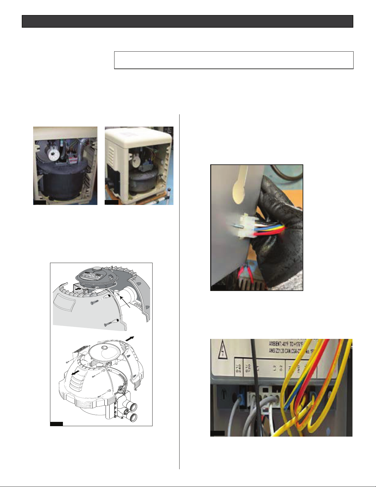
When installing this kit, basic safety precautions should always be followed. Read and follow all instructions.
Required installation tools:
• Powered socket/nut driver
• 1/4” nut driver bit
• 5/16” socket and nut driver
• 3/8” nut driver
CAUTION! Before starting: Always disconnect AC power to the heater before proceeding with
the wire harness replacement instructions.
To replace the wire harness on a MasterTemp® or Max-E-Therm® Heater:
CAUTION!: Before unplugging ICM connector plugs, be sure to match the
ZLUHLGHQWL¿FDWLRQRQERWKWKHH[LVWLQJDQGUHSODFHPHQWZLUHKDUQHVVHV
1. MasterTemp Heater: Remove right side panel from the
heater (Fig. 1 and Fig. 2).
FIG. 1
MasterTemp STD Heater MasterTemp 125 Heater
FIG. 2.
2. Max-E-Therm Heater: Unbolt the four bolts and separate
the
jackets halves. Pull hair pin clips. (Fig. 3).
3. Press the plastic clips on the control panel assembly.
4. Lift control panel assembly o of support plate.
5. Disconnect the connectors from the control panel
assembly.
7. Install wire harness (USA) (P/N 476221):
BEFORE YOU START, LAY OUT THE WIRING
HARNESS.
8. Route the 12-pin plug in the control box from the back.
The plug is shown from inside the control box. Note:
Narrow key hole in the upper right corner of the plug.
(Fig. 4).
FIG. 4.
FIG. 3.
Max-E-Therm Heater
6. LEGACY WIRE HARNESS (USA)
(P/N 42001-0104): Disconnect all connector plugs and
wires from all heater components. Remove the wire
harness from the heater.
9. Connect the 5-pin plug into the ICM from the new wire
harness as shown in Fig 21. If the heater has the legacy
ICM. Connect the 5-pin wire adapter (476205) to the corresponding terminals in the ICM (S1/120, L1, L2 and S2).
Connect the female multi-pin connector of the adapter to
the new wire harness. (Fig. 5).
FIG. 5.
3
WIRE HARNESS REPLACEMENT INSTRUCTIONS (USA)
7. Install the bushing in the top of the control box. Use
(Fig. 6)
FIG. 6.
8. Route the Red and Green wires into the Control Box
through the bottom hole. Plug the Fireman’s jumper into
the terminal board. Install bushing. Note: The plugs
are shown in the control box and the Fireman’s jumper
installed. (Fig. 7).
10. Connect the Stack Flu sensor. (Fig. 10)
FIG. 10.
11. Connect the Gas Valve. (Fig. 11).
FIG. 7
9. If the heater has a legacy ICM, connect each wire from
P/N 476204 wire adapter to its correct location labeled
in the ICM. Otherwise, connect the multi-pin connector from the Wire Harness to lower right side of ICM as
shown in Fig 8.
FIG. 8.
FIG.11.
12. Connect the Blower assembly. (Fig. 12).
FIG.12.
4

WIRE HARNESS REPLACEMENT INSTRUCTIONS (USA)
13. Connect the Air Flow Switch. (Fig. 13).
FIG. 13.
14. Connect wires to terminal board connections. Match
wire identication with terminal marking. (Fig. 14).
16. Connect F1 and F2 plug into the ICM. If the heater
has the legacy ICM, connect the 2-pin wire adapter
(476209). Connect the other end of the (476209)
adapter to the wiring harness. (Fig. 16).
FIG. 16.
17. Connect 5-pin plug into the ICM from the wire harness. If the
heater has the legacy ICM. Connect the 5-pin wire adapter
(476212) to the corresponding terminal in the ICM (lower left
side). Connect the other end of the adapter to the corresponding wires in the wire harness.
(Fig. 17).
FIG. 14.
15. From outside the Control Box, push the clip through
its hole in the back of the box. (Fig. 15).
FIG. 15.
FIG. 17.
18. Mount the bundle of wires on the blower. Plug in the blower
motor. (Fig. 18).
5
FIG. 18.

WIRE HARNESS REPLACEMENT INSTRUCTIONS (USA)
19. Plug in the transformer. (Fig. 19).
FIG. 19.
20. Route wires (HL, AGS, WP) to the manifold. (Fig. 20).
22. Connect the Water Pressure Switch and AGS switch.
The AGS is located on the right side. (Fig. 22).
FIG. 22
23. Plug the harness into the back of the circuit board.
(Fig. 23).
FIG. 20.
21. Connect the Thermistor sensor and High Limit Switch.
Note: The Thermistor sensor is located at the top of the
manifold. The High Limit switch is located at the bottom of
the manifold. (Fig. 21).
FIG. 21.
FIG. 23.
24. If the heater does not have an RS-485 port on the circuit
board, you may discard the RED and BLACK cable that
came with the wiring harness. (Fig. 24).
FIG. 24.
25. Reassemble the heater control panel assembly. Be
sure that the control panel can be adjusted without
having to lean over the exhaust vent.
6

WIRE HARNESS REPLACEMENT INSTRUCTIONS (AUSTRALIA)
F
I
L
T
E
R
P
U
M
P
A
U
X
1
A
U
X
2
H
I
G
H
S
PE
E
D
L
O
W
S
P
E
ED
B
O
O
S
TE
R
P
U
M
P
Retaining
Pins
When installing this kit, basic safety precautions should always be followed. Read and follow all instructions.
Required installation tools:
• Powered socket/nut driver
• 1/4” nut driver bit
• 5/16” socket and nut driver
• 3/8” nut driver
CAUTION! Before starting: Always disconnect AC power to the heater before proceeding with
the wire harness replacement instructions.
To replace the wire harness on a MasterTemp® or Max-E-
®
Therm
Heater:
1. MasterTemp Heater: Remove right side panel from the heater
(Fig. 1 and Fig. 2).
CAUTION!: Before unplugging ICM connector plugs, be sure to match the
ZLUHLGHQWL¿FDWLRQRQERWKWKHH[LVWLQJDQGUHSODFHPHQWZLUHKDUQHVVHV
8. Place the 12-pin plug in the control box from the back.
The plug is shown from outside the control box. Note:
narrow key in upper right corner of plug. (FIg. 4)
FIG. 1.
FIG. 2.
MasterTemp STD Heater MasterTemp 125 Heater
2. Max-E-Therm Heater: Unbolt the four bolts and separate the
jackets halves. Pull hair pin clips. (Fig. 3).
3. Press the plastic clips on the control panel assembly.
4. Lift control panel assembly o of support plate.
5. Disconnect the connectors from the control panel assembly.
FIG. 4.
9. Put the Flat-5 pin plug, 2-pin plug and multi-pin
connector into the control box. Install the bushing if the
heater has a new control board (with an RS-485 port
connection. Also, put the Flame current cable into the
control box. (Fig. 5).
FIG. 5.
FIG. 3.
Max-E-Therm Heater
6. LEGACY WIRE HARNESS (USA) (P/N 42001-0104): Disconnect
all connector plugs and wires from all heater components. Remove
the wire harness from the heater.
7. Install wire harness (USA) (P/N 476221):BEFORE YOU START,
LAY OUT THE WIRING HARNESS.
7

WIRE HARNESS REPLACEMENT INSTRUCTIONS (AUSTRALIA)
10. Route the Red and Green wires into the Control Box through
the bottom hole. Plug the Fireman’s jumper into the terminal board. Install bushing. Note: The plugs are shown in the
control box and the Fireman’s jumper installed. (Fig. 6).
FIG. 6.
11. Connect 5-pin plug to the lower left side of the ICM. Connect
the S1/240 gray wire to the left side of the 5-pin plug. (Fig. 7).
13. Connect 240VAC gray cable with ¼” female terminal to ¼”
tab at the lower left side of ICM. (Fig. 9)
FIG. 9.
14. Connect the Blue/Yellow wire to TH ¼” tab at ICM.
(Fig. 10).
FIG. 7.
12. Connect wires to terminal board connections. Match
wire identication with terminal marking. (Fig. 8).
FIG. 8.
FIG. 10.
15. Connect the Orange/Yellow wire to IND ¼” tab at ICM.
(Fig. 11).
FIG. 11.
8

WIRE HARNESS REPLACEMENT INSTRUCTIONS (AUSTRALIA)
16. Connect the Red/yellow wire to VAL ¼” tab at the ICM.
(Fig. 12).
FIG. 12.
17. Connect the White/Yellow wire to GND ¼” tab at the ICM.
(Fig. 13).
19. From outside the Control Box, push the clip through its hole in
the back of the box. (Fig. 15).
FIG. 15.
20. Connect the 2 pin adapter wire to F1 and F2 at the ICM. Connect the other end of the 476209 adapter to the wiring
harness. (Fig. 16).
FIG. 13.
18. Connect the 24 VAC plug at the upper right side as shown in
Fig. 14.
FIG. 14.
FIG. 16.
21. Connect the 5-pin plug into the ICM from the new wire
harness as shown in g 17. If the heater has the legacy
ICM. Connect the 5-pin wire adapter (476205) to the corresponding terminals in the ICM (s1/120, L1, L2 and S2).
Connect the female multi pin connector of the adapter to
the new wire harness. (Fig. 17).
FIG. 17.
9

WIRE HARNESS REPLACEMENT INSTRUCTIONS (AUSTRALIA)
22. Mount the bundle on the blower plug in the blower
motor. (Fig. 18).
FIG. 18.
23. Plug in the transformer. (Fig. 19).
25. Connect the Thermistor sensor and High Limit Switch. Note:
The Thermistor sensor is located at the top of the manifold.
The High Limit switch is located at the bottom of the manifold.
(Fig. 21).
FIG. 21.
26. Connect the Water pressure switch, High limit switch
(45°) in the top port of the manifold and the AGS switch
located on the right side of the manifold. (Fig 22).
FIG. 19.
24. Run wires (HL, AGS, WP, etc) to the manifold. (Fig. 20).
FIG. 20.
FIG. 22.
10

WIRE HARNESS REPLACEMENT INSTRUCTIONS (AUSTRALIA)
27. Plug the harness into the back of the board. (Fig. 23.)
FIG. 23.
28. If the heater does not have an RS-485 port on the circuit
board, you may discard the RED and BLACK cable that
came with the wiring harness. (Fig. 24).
31. Connect the Gas Valve. (Fig. 26.).
FIG. 26.
32. Connect the Air Flow Switch. (Fig. 27).
FIG. 24.
29. Reassemble the heater control panel assembly. Be
sure that the control panel can be adjusted without
having to lean over the exhaust vent.
30. Connect the Stack Flu sensor. (Fig. 25).
FIG. 27.
33. Connect the cables that supply power to the heater. (Fig. 28).
FIG. 28.
34. Reassemble the heater control panel assembly. Be
sure that the control panel can be adjusted without
having to lean over the exhaust vent.
FIG. 25.
11

1620 HAWKINS AVE., SANFORD, NC 27330 • (919) 566-8000
10951 WEST LOS ANGELES AVE., MOORPARK, CA 93021 • (805) 553-5000
Technical Support: 800.831.7133
www.pentair.com
All indicated Pentair trademarks and logos are property of Pentair Inc. or its global aliates in the U.S.A. and/or other countries. Third
party registered and unregistered trademarks and logos are the property of their respective owners
© 2020 Pentair. All rights reserved. This document is subject to change without notice.
* 476250*
P/N 476250.A 9/2020
 Loading...