

Page 1
®
WHISPERFLOXF
®
MAX-E-PROXF
COMMERCIAL VARIABLE SPEED PUMP
VS AND
VS
INSTALLATION AND
USER’S GUIDE
IMPORTANT SAFETY INSTRUCTIONS
READ AND FOLLOW ALL INSTRUCTIONS
SAVE THESE INSTRUCTIONS
Page 2

i
CUSTOMER SERVICE / TECHNICAL SUPPORT
If you have questions about ordering Pentair replacement parts, and pool products, please contact:
Customer Service and Technical Support, USA
(8 A.M. to 4:30 P.M. — Eastern/Pacific Times)
Phone: (800) 831-7133
Fax: (800) 284-4151
Web site
Visit www.pentair.com for information about our products.
TABLE OF CONTENTS
Important Pump Warning and
Safety Instructions ..............................................
Pump Overview .....................................................
Drive Assembly and Control Panel
Motor Features
Drive Features
Installation .............................................................
Location
Piping
Fittings and Valves
Electrical Requirements
Electrical Installation
Wiring, Grounding and Bonding
Operation ...............................................................
Using the Control Panel Keypad
Setting the Clock
Factory Default Schedule
Programming Custom Schedules
Program Priorities
Priming the Pump
Priming Adjustment
Operating the Pump While Running
Quick Clean
Keypad Lockout
Factory Reset
External Controls or Digital Inputs .....................
Control with External Control and Digital Inputs
Connecting to External Control
External Control Only Mode
Operating the Pump in Flow Mode
Flow Mode Setup and Configuration
Adjusting Flow Setting
ii
1
1
1
1
2
2
2
2
2
3
3
4
4
5
5
5
6
7
8
9
10
10
11
12
12
12
13
13
13
14
Sanford, North Carolina (8 A.M. to 4:30 P.M. ET)
Phone: (919) 566-8000
Fax: (919) 566-8920
Moorpark, California (8 A.M. to 4:30 P.M. PT)
Phone: (805) 553-5000 (Ext. 5591)
Fax: (805) 553-5515
Maintenance ..........................................................
Cleaning the Pump Strainer Basket
Winterizing
Servicing ...............................................................
Motor and Drive Care
Mechanical Seal
Pump Disassembly
Pump Reassembly/Seal Replacement
Removing and Replacing the Drive Assembly
Troubleshooting ....................................................
Problems and Corrective Actions
Faults and Alarms
Replacement Parts ...............................................
Replacement Parts List
Technical Data ......................................................
Performance Curves
Pump Dimensions
Electrical Specifications
Mechanical Specifications
15
15
15
16
16
16
16
17
18
19
19
21
22
22
23
23
23
23
23
* Translated versions of this manual are available online at / La versión en español de este manual del producto, se puede encontrar en
línea a /
https://www.pentair.com/content/pentair/en/products/pool-spa-equipment/pool-pumps/whisperfloxf-variable-speed-pump.html
https://www.pentair.com/content/pentair/en/products/pool-spa-equipment/pool-pumps/max-e-proxf-variable-speed-pump.html
P/N 358077 Rev. A 5/16/19
WHISPERFLOXF® VS and MAX-E-PROXF® VS Commercial Variable Speed Pump Installation and User’s Guide
La version française de ce manuel est disponible à
:
Page 3

IMPORTANT PUMP WARNING AND SAFETY INSTRUCTIONS
F
IMPORTANT NOTICE
This guide provides installation and operation instructions for this product.
Consult Pentair with any questions regarding this equipment.
Attention Installer: This guide contains important information about the
installation, operation and safe use of this product. This information should
be given to the owner and/or operator of this equipment after installation or
left on or near the pump.
Attention User: This manual contains important information that will help
you in operating and maintaining this product. Please retain it for future
reference.
READ AND FOLLOW
ALL INSTRUCTIONS
SAVE THESE INSTRUCTIONS
This is the safety alert symbol. When you see this
symbol on your system or in this manual, look for
one of the following signal words and be alert to the
potential for personal injury.
Warns about hazards that can cause death, serious
personal injury, or major property damage if ignored.
Warns about hazards that may cause death, serious
personal injury, or major property damage if ignored.
Warns about hazards that may or can cause minor
personal injury or property damage if ignored.
NOTE Indicates special instructions not related to
hazards.
Carefully read and follow all safety instructions in this manual and on
equipment. Keep safety labels in good condition; replace if missing or
damaged.
ii
General Warnings
• Never open the inside of the drive motor enclosure. There is a
capacitor bank that holds a 230 VAC charge even when there is no
power to the unit.
• The pump is not submersible.
• The pump is capable of high flow rates; use caution when installing
and programming to limit pumps performance potential with old or
questionable equipment.
• Code requirements for electrical connection differ from country to
country, state to state, as well as local municipalities. Install equipment
in accordance with the National Electrical Code and all applicable
local codes and ordinances.
• Before servicing the pump; switch OFF power to the pump by
disconnecting the main circuit to the pump.
• This appliance is not intended for use by persons (including children) of
reduced physical, sensory or mental capabilities, or lack of experience
and knowledge, unless they have been given supervision or instruction
concerning the use of the appliance by a person responsible for their
safety.
FAILURE TO FOLLOW ALL INSTRUCTIONS AND
WARNINGS CAN RESULT IN SERIOUS BODILY
INJURY OR DEATH. THIS PUMP SHOULD BE INSTALLED AND
SERVICED ONLY BY A QUALIFIED POOL SERVICE PROFESSIONAL.
INSTALLERS, POOL OPERATORS AND OWNERS MUST READ THESE
WARNINGS AND ALL INSTRUCTIONS IN THE OWNER’S MANUAL
BEFORE USING THIS PUMP. THESE WARNINGS AND THE OWNER’S
MANUAL MUST BE LEFT WITH THE POOL OWNER.
SUCTION ENTRAPMENT HAZARD: STAY OFF
THE MAIN DRAIN AND AWAY FROM ALL SUCTION
OUTLETS!
When installing and using this electrical equipment, basic safety precautions
should always be followed, include the following:
Do not permit children to use this product.
RISK OF ELECTRICAL SHOCK (For all permanently
installed units intended for use on 15 or 20 ampere, 125
through 240 volt, single phase branch circuits). Connect only to a branch
circuit protected by a ground-fault circuit-interrupter (GFCI). Contact a
qualified electrician if you cannot verify that the circuit is protected by a GFCI.
This unit must be connected only to a supply circuit that is protected by a
ground-fault circuit-interrupter (GFCI). Such a GFCI should be provided by
the installer and should be tested on a routine basis. To test the GFCI, push
the test button. The GFCI should interrupt power. Push the reset button.
Power should be restored. If the GFCI fails to operate in this manner, the
GFCI is defective. If the GFCI interrupts power to the pump without the test
button being pushed, a ground current is flowing, indicating the possibility
of an electric shock. Do not use this pump. Disconnect the pump and have
the problem corrected by a qualified service representative before using.
This pump is for use with permanent swimming pools
and may also be used with hot tubs and spas if so
marked. Do not use with storable pools. A permanently-installed pool is
constructed in or on the ground or in a building such that it cannot be
readily disassembled for storage. A storable pool is constructed so that it
is capable of being readily disassembled for storage and reassembled to
its original integrity.
THIS PUMP PRODUCES HIGH LEVELS OF SUCTION AND CREATES
A STRONG VACUUM AT THE MAIN DRAIN AT THE BOTTOM OF THE
BODY OF WATER. THIS SUCTION IS SO STRONG THAT IT CAN TRAP
ADULTS OR CHILDREN UNDER WATER IF THEY COME IN CLOSE
PROXIMITY TO A DRAIN OR A LOOSE OR BROKEN DRAIN COVER
OR GRATE.
THE USE OF UNAPPROVED COVERS OR ALLOWING USE OF THE
POOL OR SPA WHEN COVERS ARE MISSING, CRACKED OR BROKEN
CAN RESULT IN BODY OR LIMB ENTRAPMENT, HAIR ENTANGLEMENT, BODY ENTRAPMENT, EVISCERATION AND/OR DEATH.
The suction at a drain or outlet can cause:
Limb Entrapment: When a limb is sucked or inserted into an opening
resulting in a mechanical bind or swelling. This hazard is present when
a drain cover is missing, broken, loose, cracked or not properly secured.
Hair Entanglement: When the hair tangles or knots in the drain cover,
trapping the swimmer underwater. This hazard is present when the flow
rating of the cover is too small for the pump or pumps.
Body Entrapment: When a portion of the body is held against the drain
cover trapping the swimmer underwater. This hazard is present when the
drain cover is missing, broken or the cover flow rating is not high enough
for the pump or pumps.
Evisceration/Disembowelment: When a person sits on an open pool
(particularly a child wading pool) or spa outlet and suction is applied directly
to the intestines, causing severe intestinal damage. This hazard is present
when the drain cover is missing, loose, cracked, or not properly secured.
WHISPERFLOXF® VS and MAX-E-PROXF® VS Commercial Variable Speed Pump Installation and User’s Guide
Page 4
iii
IMPORTANT PUMP WARNING AND SAFETY INSTRUCTIONS
Mechanical Entrapment: When jewelry, swimsuit, hair decorations,
finger, toe or knuckle is caught in an opening of an outlet or drain cover.
This hazard is present when the drain cover is missing, broken, loose,
cracked, or not properly secured.
NOTE: ALL SUCTION PLUMBING MUST BE INSTALLED IN
ACCORDANCE WITH THE LATEST NATIONAL AND LOCAL CODES,
STANDARDS AND GUIDELINES.
TO MINIMIZE THE RISK OF INJURY DUE TO
SUCTION ENTRAPMENT HAZARD:
• A properly installed and secured ANSI/ASME A112.19.8 approved
anti-entrapment suction cover must be used for each drain.
• Each suction cover must be installed at least three (3’) feet apart,
as measured from the nearest point to nearest point.
• Regularly inspect all covers for cracks, damage and advanced
weathering.
• If a cover becomes loose, cracked, damaged, broken or is missing,
replace with an appropriate certified cover.
• Replace drain covers as necessary. Drain covers deteriorate over
time due to exposure to sunlight and weather.
• Avoid getting hair, limbs or body in close proximity to any suction
cover, pool drain or outlet.
• Disable suction outlets or reconfigure into return inlets.
The Virginia Graeme Baker (VGB) Pool and Spa Safety Act creates
new requirements for owners and operators of commercial swimming
pools and spas.
Commercial pools or spas constructed on or after December 19, 2008,
shall utilize:
(A) A multiple main drain system without isolation capability with suction
outlet covers that meet ASME/ANSI A112.19.8a Suction Fittings for
Use in Swimming Pools, Wading Pools, Spas, and Hot Tubs and either:
(i) A safety vacuum release system (SVRS) meeting ASME/ANSI
A112.19.17 Manufactured Safety Vacuum Release systems (SVRS)
for Residential and Commercial Swimming Pool, Spa, Hot Tub,
and Wading Pool Suction Systems and/or ASTM F2387 Standard
Specification for Manufactured Safety Vacuum Release Systems
(SVRS) for Swimming pools, Spas and Hot Tubs or
(ii) A properly designed and tested suction-limiting vent system or
(iii) An automatic pump shut-off system.
Commercial pools and spas constructed prior to December 19, 2008,
with a single submerged suction outlet shall use a suction outlet cover
that meets ASME/ANSI A112.19.8a and either:
(A) A SVRS meeting ASME/ANSI A112.19.17 and/or ASTM F2387, or
(B) A properly designed and tested suction-limiting vent system, or
(C) An automatic pump shut-off system, or
(D) Disabled submerged outlets, or
(E) Suction outlets shall be reconfigured into return inlets.
HAZARDOUS PRESSURE: STAND CLEAR OF
PUMP AND FILTER DURING START UP
Circulation systems operate under high pressure.
When any part of the circulating system (i.e.
locking ring, pump, filter, valves, etc.) is serviced,
air can enter the system and become pressurized.
Pressurized air can cause the pump housing cover
filter lid and valves to violently separate which can result in severe personal
injury or death. Filter tank lid and strainer cover must be properly secured to
prevent violent separation. Stand clear of all circulation system equipment
when turning on or starting up pump.
Before servicing equipment, make note of the filter pressure. Be sure
that all controls are set to ensure the system cannot inadvertently start
during service. Turn off all power to the pump. IMPORTANT: Place filter
manual air relief valve in the open position and wait for all pressure
in the system to be relieved.
Before starting the system, fully open the manual air relief valve and place
all system valves in the “open” position to allow water to flow freely from the
tank and back to the tank. Stand clear of all equipment and start the pump.
IMPORTANT: Do not close filter manual air relief valve until all
pressure has been discharged from the valve and a steady stream
of water appears. Observe filter pressure gauge and be sure it is not
higher than the pre-service condition.
General Installation Information
• All work must be performed by a qualified service professional, and
must conform to all national, state, and local codes.
• Install to provide drainage of compartment for electrical components.
• These instructions contain information for a variety of pump models
and therefore some instructions may not apply to a specific model. All
models are intended for use in swimming pool applications. The pump
will function correctly only if it is properly sized to the specific application
and properly installed.
Pumps improperly sized or installed or used in
applications other than for which the pump was
intended can result in severe personal injury or death. These risks
may include but not be limited to electric shock, fire, flooding, suction
entrapment or severe injury or property damage caused by a structural
failure of the pump or other system component.
The pump can produce high levels of suction within
the suction side of the plumbing system. These
high levels of suction can pose a risk if a person comes within the close
proximity of the suction openings. A person can be seriously injured
by this high level of vacuum or may become trapped and drown. It is
absolutely critical that the suction plumbing be installed in accordance
with the latest national and local codes for swimming pools.
For Installation of Electrical Controls at Equipment Pad (ON/OFF
Switches, Timers and Automation Load Center)
Install all electrical controls at equipment pad, such as
on/off switches, timers, and control systems, etc. to
allow the operation (startup, shut-down, or servicing)
of any pump or filter so the user does not place any
portion of his/her body over or near the pump strainer
lid, filter lid or valve closures. This installation should
allow the user enough space to stand clear of the filter and pump during
system start-up, shut down or servicing of the system filter.
A clearly labeled emergency shut-off switch for the
pump must be in an easily accessible, obvious place.
Make sure users know where it is and how to use it in case of emergency.
WHISPERFLOXF® VS and MAX-E-PROXF® VS Commercial Variable Speed Pump Installation and User’s Guide
Warnings and safety instructions for Pentair Water Pool and Spa, Inc.
pumps and other related products are available at:
http://www.pentairpool.com/pool-owner/safety-warnings/ or call
(800) 831-7133 for additional free copies of these instructions.
Please refer to http://www.pentairpool.com/pool-owner/
safetywarnings/ for warning and safety instructions related to this
product.
SAVE THESE INSTRUCTIONS
Warning Page P/N 352558 Rev. A 6/15
Page 5
PUMP OVERVIEW
1
The WhisperFloXF® VS or Max-E-ProXF® VS Commercial
Variable Speed Pump can be programmed to run at specific
speeds and time intervals for maximum operating efficiency
and energy conservation for a variety of inground pools.
• The pump can operate at any speed between 300 RPM
to 3450 RPM for different applications, with four preset
speeds of 1720, 2500, 3000 and 3450 (Quick Clean).
• Pump control panel alarm LED and error messages
warn the user against under and over voltage, high
temperature and over current.
• Communicates with most Pentair automation systems
via digital input connection (External Control Wiring
Kit, P/N 353129Z).
• Adjustable priming mode for easy start-up
• Compatible with most cleaning systems, filters, and jet
action spas
• WEF 5.0 THP 5.0
Drive Assembly and Control Panel
The pump’s drive is designed to produce maximum motor
operational efficiency. The drive controls the motor’s
rotational speed by controlling the frequency of the supplied
current. It also protects the motor and pump from operating
outside of their intended operating parameters.
Motor Features
• Superior speed control for commercial applications
• Operates at lower temperatures due to high
efficiency
• Designed to withstand outdoor environment
• Totally Enclosed Fan Cooled (TEFC) Motor
• 56 Square Flange
• Low noise
Drive Features
• Active Power Factor Correction
• High Drive Operational Efficiency
• Flow Control Capable When Paired with a 4-20mA
Flowmeter (Pentair P/N 97014-4203KIT).
• Versatile power input:
– Single-Phase, 208-230/277-460V, 20-21/17-11A
– 3-Phase, 208-460V, 13-6A
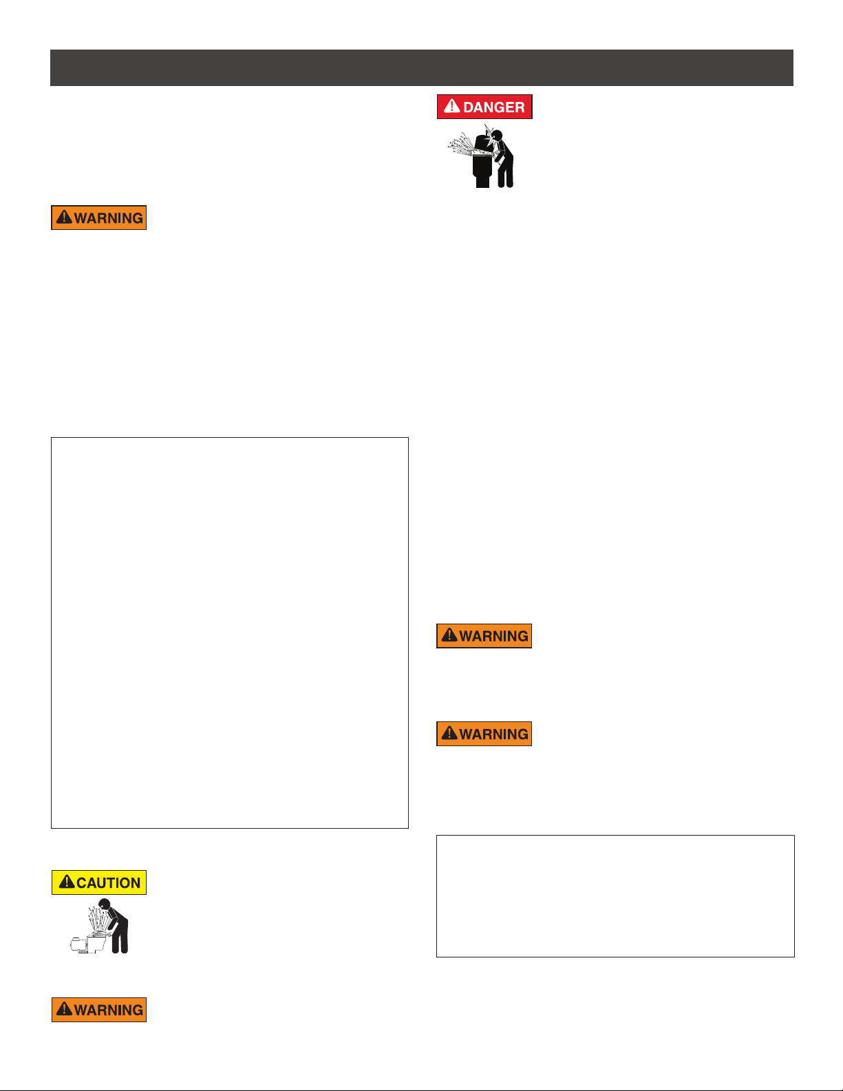
Digital input port
for connection
to automation or
4-20mA flowmeter
Wiring
Compartment
for Incoming
AC Power
Control Panel Keypad Cover
(Buttons and LEDs Beneath)
Union Kit
(Suction and Discharge Fittings)
Pump Overview
WHISPERFLOXF® VS and MAX-E-PROXF® VS Commercial Variable Speed Pump Installation and User’s Guide
Page 6
2
INSTALLATION
Only a qualified plumbing professional should install the WhisperFloXF® VS and Max-E-ProXF® VS Commercial
Variable Speed Pumps. Refer to “Important Pump Warning And Safety Instructions” on pages ii - iii for additional
installation and safety information.
Location
Note: Do not install this pump within an outer
enclosure or beneath the skirt of a hot tub or spa
unless marked accordingly.
Note: Ensure that the pump is mechanically secured
to the equipment pad.
Be sure the pump location meets the following
requirements:
1. Install the pump as close to the pool or spa as
possible. To reduce friction loss and improve
efficiency, use short, direct suction and return
piping.
2. Install a minimum of 5 feet (1.52 meters) from
the inside wall of the pool and spa. Canadian
installations require a minimum of 9.8 feet (3
meters) from the inside wall of the pool.
3. Install the pump a minimum of 3 feet (.9 meters)
from the heater outlet.
4. Do not install the pump more than 10 feet (3.1
meters) above the water level.
5. Install the pump in a well ventilated location
protected from excess moisture (i.e. rain gutter
downspouts, sprinklers, etc.).
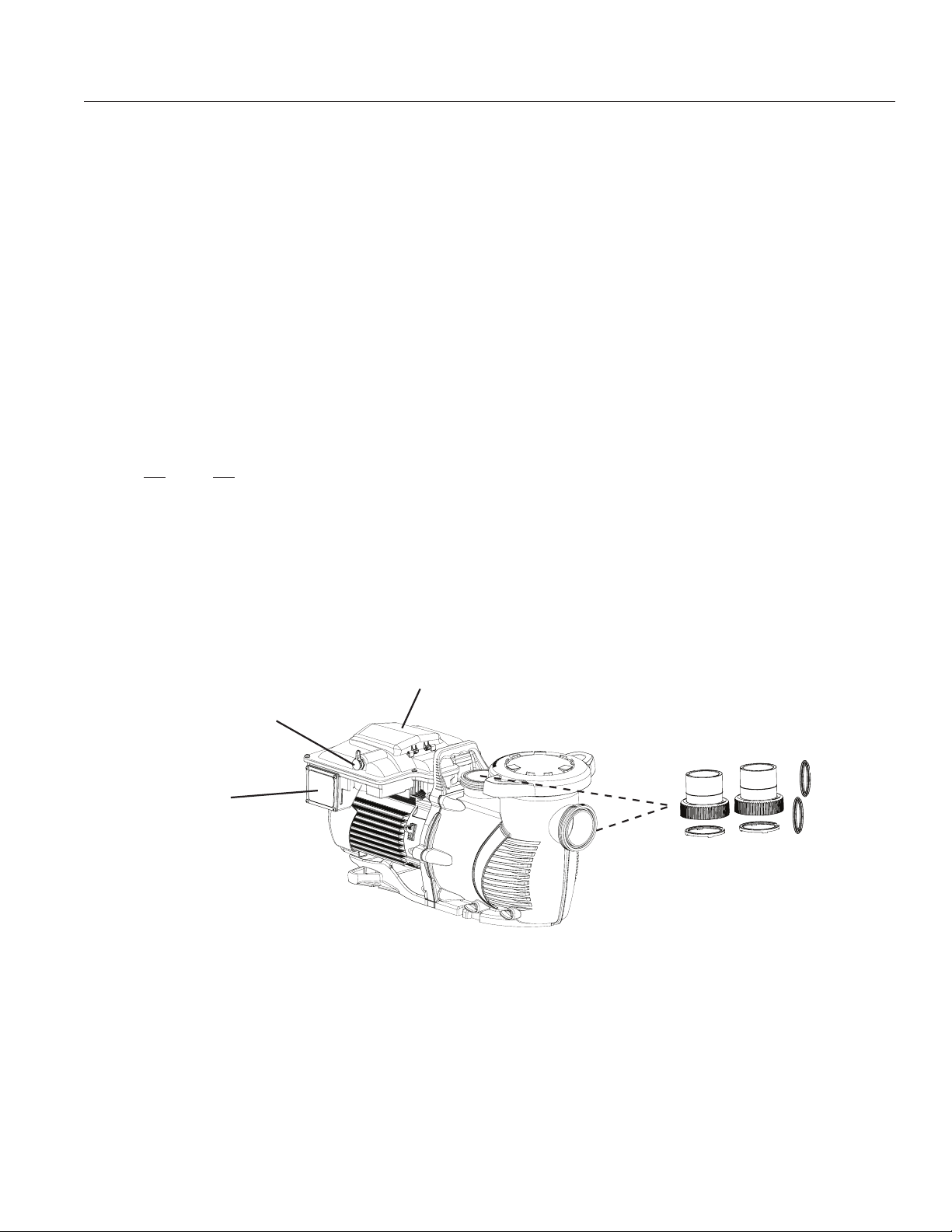
6. Install the pump with a rear clearance of at least 3
inches (7.6 cm) so that the motor can be removed
easily for maintenance and repair. See Figure 1.
Piping
1. For improved pool plumbing, it is recommended to
use a larger pipe size.
2. Piping on the suction side of the pump should be
the same or larger than the return line diameter.
3. Plumbing on the suction side of the pump should
be as short as possible.
4. For most installations Pentair recommends
installing a valve on both the pump suction and
return lines so that the pump can be isolated
during routine maintenance. However, we also
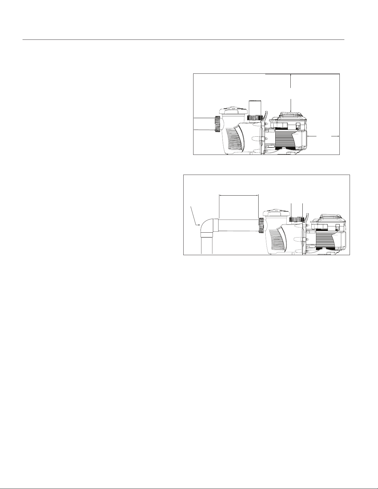
recommend that a valve, elbow or tee installed in
the suction line should be no closer to the front
of the pump than five (5) times the suction line
diameter. See Figure 2.
Example: A 2.5 inch pipe requires a 12.5 inch
(31.8 cm) straight run in front of the suction inlet of
the pump. This will help the pump prime faster and
last longer.
Note: DO NOT install 90° elbows directly into the
pump inlet or outlet.
Figure 1: Pump Rear and Vertical Clearance
5 x SUCTION
PIPE DIAMETER
ELBOW
Figure 2: Recommended Piping
Fittings and Valves
1. Do not install 90° elbows directly into pump inlet.
2. Flooded suction systems should have gate
valves installed on suction and discharge pipes
for maintenance, however, the suction gate valve
should be no closer than five times the suction pipe
diameter as described in this section.
3. Use a check valve in the discharge line when
using this pump for any application where there is
significant height to the plumbing after the pump.
4. Be sure to install check valves when plumbing in
parallel with another pump. This helps prevent
reverse rotation of the impeller and motor.
Electrical Requirements
• Install all equipment in accordance with the National
Electrical code and all applicable local codes and
ordinances.
• A means for disconnection must be incorporated in
the fixed wiring in accordance with the wiring rules.
6 IN. (15.2 CM)
MINIMUM
3 IN.
(7.6 CM)
MINIMUM
WHISPERFLOXF® VS and MAX-E-PROXF® VS Commercial Variable Speed Pump Installation and User’s Guide
Page 7
Electrical Installation
RISK OF ELECTRICAL SHOCK OR ELECTROCUTION. This pump must be installed by a licensed or certified electrician or
a qualified service professional in accordance with the National Electrical Code and all applicable local codes and ordinances.
Improper installation will create an electrical hazard which could result in death or serious injury to users, installers, or others due to
electrical shock, and may also cause damage to property.
Always disconnect power to the pump at the circuit breaker before servicing the pump. Failure to do so could result in death
or serious injury to service people, users or others due to electric shock.
Read all servicing instructions before working on the pump.
Note: ALWAYS reinstall the cover onto the field wiring compartment when leaving the pump unsupervised during
servicing. This will prevent foreign matter (i.e. rainwater, dust, etc.) from accumulating inside the compartment.
Note: When connecting the pump to an automation system, continuous power must be supplied to the pump
by connecting it directly to the circuit breaker. When using an automation system, be sure that no other lights or
appliances are on the same circuit.
3
Wiring
1. Be sure all electrical breakers and switches are
turned off before wiring motor.
STORED CHARGE - Wait at least sixty
(60) seconds before servicing.
2. Be sure that the supply voltage meets the
requirements listed on the motor nameplate. If these
requirements are not met, permanent motor damage
may occur.
3. For wiring sizes and general guidelines for proper
electrical installation, please follow the specifications
defined in the National Electric Code and any local
codes as required.
4. Use a strain relief and be sure all electrical
connections are clean and tight.
5. Cut the wires to the appropriate length so they do
not overlap or touch when connected.
6. Wire the pump according to instructions given on the
inside of the field wiring cover, then secure the field
wiring cover with the four (4) corner screws.
7. DO NOT install motor starters on these pumps.
These devices can cause low input voltage alarms.
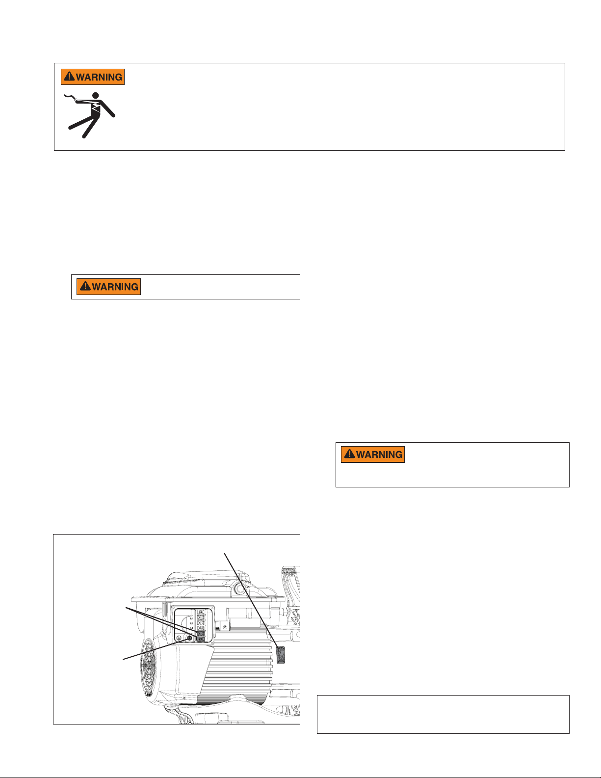
Bonding Lug
Factory-Installed
Surge Jumper
Ground Wire
Connection
(Green Screw)
Grounding
1. Permanently ground the motor using the green
ground screw (see Figure 3). Use the correct wire
size and type specified by National Electrical Code.
Be sure the ground wire is connected to an electrical
service ground.
2. The pump should be permanently connected to either
a circuit breaker, 2-pole timer or 2-pole relay.
Note: If AC power is supplied by a GFCI circuit
breaker, the pump should be wired on its own
independent circuit unless the pump is operated in
tandem with a Pentair salt chlorine generator.
3. A surge jumper has been factory-installed between
the two (2) bottom screw terminals in the wiring
compartment. Ensure this surge jumper is in place
before wiring the pump. See Figure 3.
This surge jumper grounds all drive
components and will protect them from
repeated voltage surges. If surge jumper is not installed
damage to the pump drive may occur.
Bonding
1. Bond the motor to the structure in accordance with
the National Electrical Code. Use a solid copper
bonding conductor not smaller than 8 AWG. For
Canadian installations, a 6 AWG or larger solid
copper bonding conductor is required. Run a wire
from the external bonding screw or lug to the bonding
structure.
2. Connect the wire from the accessible bonding lug
on the motor to all metal parts of the swimming
pool, spa, or hot tub structure and to all electrical
equipment, metal conduit, and metal piping within 5
feet (1.52 meters) of the inside walls of the swimming
pool, spa, or hot tub. Run a wire from the external
bonding lug to the bonding structure. See Figure 3.
Figure 3
Note: When the pump is started and stopped by removing
power with a relay or timer, a two-pole device should be used to
apply and remove power to both POWER LINE TERMINALS.
WHISPERFLOXF® VS and MAX-E-PROXF® VS Commercial Variable Speed Pump Installation and User’s Guide
Page 8
4
OPERATION
Before operating the pump for the first time, the pump’s internal clock and operational schedules must be programmed
by following the steps in this manual. Please refer to “Setting the Clock” and “Custom Schedules”, on page 5, for
instructions regarding the programming of this pump for scheduled operation.
This pump is capable of maintaining either constant speeds or constant flows. The factory default drive settings is Speed
Control. For information on configuring the pump for Flow Control via 4-20mA flowmeter, refer to Operating the Pump in
Flow Mode on pages 13-14.
Using the Control Panel Keypad
The WhisperFloXF® VS or Max-E-ProXF® VS Commercial Variable Speed Pump is programmed and controlled via the
control panel keypad. Pump features and settings are also accessed using this keypad.
Note: Always close the keypad cover after use. This will prevent preventable damage to the keypad and other drive
components.
Only press keypad buttons with your fingers. Using screwdrivers, pens or other tools to program the pump will damage the keypad.
If power is connected to the pump motor, pressing any of the following buttons referred to in this section could result in the motor
starting. Failure to recognize this could result in personal injury or damage to equipment.
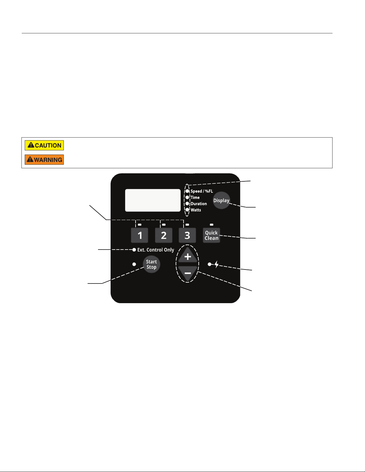
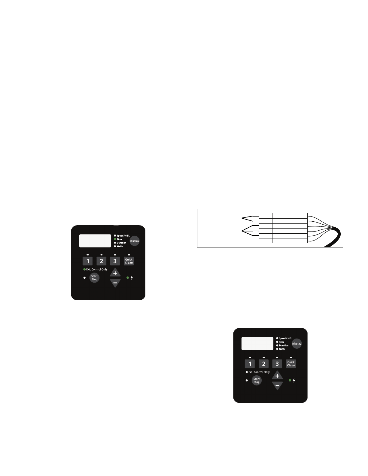
(4) Display Mode LED
Indicators
(1) Program Buttons
(5) Display Button
(2) External
Control Only
(6) Quick Clean
Button
LED Indicator
(7) Power LED
Indicator
(3) Start/Stop
Button
(8) “+” and “-”
Arrows
1. Program Buttons - Used to select the desired program. The LED above the Program Buttons will illuminate when
that program is selected or is currently running. A flashing LED indicates that an External Control is active on that
program’s channel.
2. External Control Only LED Indicator - Indicates that the pump is operating in External Control mode. When LED
is illuminated the schedule is disabled and the only input is from the low voltage external controls.
3. Start/Stop Button - Used to Start and Stop the pump. When the pump is stopped and the LED is not illuminated,
the pump is unable to run from any type of input.
4. Display Mode LED Indicators - An illuminated LED indicates the information being displayed on the screen at any
specific point. A flashing LED indicates that the parameter is currently being edited.
5. Display Button - Used to toggle between the different available display modes. This button is also used to set the
24-hour clock and screen resolution.
6. Quick Clean Button - Used to run a selected speed and duration programmed for Quick Clean. When the LED is
illuminated a Quick Clean cycle is active.
7. Power LED Indicator - An illuminated LED indicates that there is live power being supplied to the pump.
8. “+” and “-” Arrows - Used to make on screen adjustments to the pump settings. The “+” arrow increases the value
of a given setting, while “-” decreases the value of a given setting. Pressing and holding down either arrow button
will increase or decrease the incremental changes faster.
WHISPERFLOXF® VS and MAX-E-PROXF® VS Commercial Variable Speed Pump Installation and User’s Guide
Page 9
5
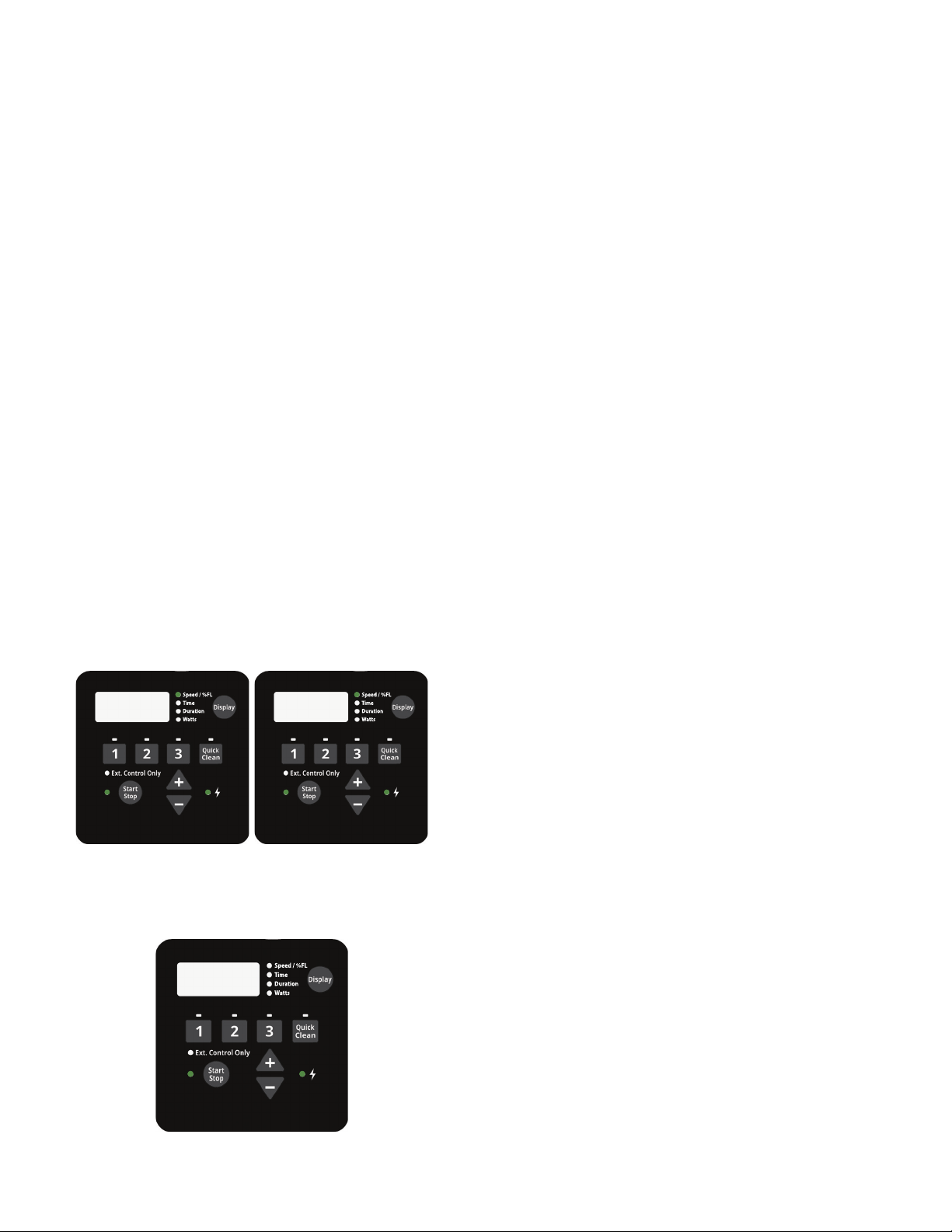
Setting the Clock
When the pump is first plugged in, the clock will blink to
indicate that is has not been set. Any daily schedule set
by the user will be based on this clock setting, so it will
be necessary to set the clock first.
To Set the Clock:
1. Hold the Display button for 3 seconds.
2. Use the “+” and “-” arrows to choose between a 12
or 24 hour time format.
3. Press Display to advance in the Clock Setup menu.
4. Use the “+” and “-” arrows to change the time to the
correct time of day. In the 12 hour time format AM/
PM will display in the bottom right corner.
5. Press Display to advance.
6. Use the “+” and “-” arrows to adjust the screen
backlight brightness.
7. Press Display to exit the Clock Setup menu. The
clock is now set.
During a power outage, the drive will retain the clock
setting in memory for as long as 24 hours. If the power
is out longer than 24 hours the clock will have to be set
again. If the drive has lost the user set time, the clock will
continuously blink until the time is reset. Once the time is
reset the clock will stop blinking.
Note: When power is returned to the pump after a
prolonged outage (24+ hours) the clock will automatically
set itself to the PROGRAM 1 start time, blink and
advance. The pump will also run the associated schedule
from that start time.
Programming Custom Schedules
To customize the run schedule for your WhisperFloXF®
VS or Max-E-ProXF® VS Commercial Variable Speed
Pump, the pump must be stopped. Be sure that the
Start/Stop button LED is not illuminated.
Programming a Custom Schedule:
Note: The clock must be set before programming a
custom schedule.
Note: When programming, the LED light next to the
parameter (“Spd
setting will blink.
1. Stop the pump if it is running by pressing the Start/
Stop button.
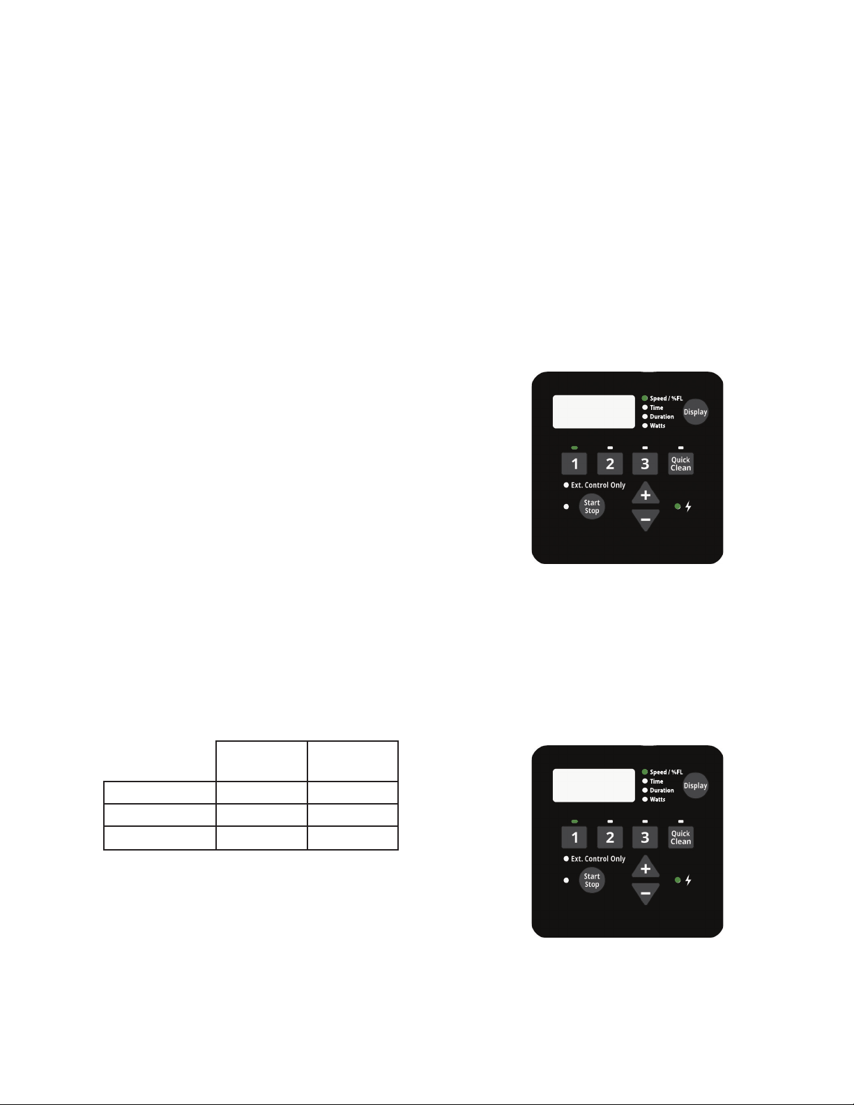
2. Press the “1” button. The LED above the selected
PROGRAM will begin to blink and the “Spd
parameter LED will blink while editing. See Figure 4.
/
%FL”, “Time” and “Duration”) you are
/
%FL”
3000
Figure 4: Setting Speed
Factory Default Schedule
The default schedule is designed to provide enough daily
turnover to service a typical pool. See Table 1 for default
schedule.
Note: The Start/Stop button must be pressed, and the
LED lit, for the pump to run.
Duration
(Hours)
PROGRAM 1 24 1720
PROGRAM 2 0 2500
PROGRAM 3 0 3000
Table 1: Default Schedule
Speed
(RPM)
3. Use the “+” and “-” arrows to adjust the speed in
RPM, or percentage of flow if operating in Flow
Mode, for PROGRAM 1.
Note: Speed is adjusted up or down by increments
of 10 RPM. Flow is adjusted in 5-percent increments.
4. Press the “1” button again and the display will
change to PROGRAM 1 start time. The “Time”
parameter LED will begin to blink. See Figure 5.
8:00am
Figure 5: Setting Start Time
5. Use the “+” and “-” arrows to adjust the daily start
time for PROGRAM 1.
- Continue to next page -
WHISPERFLOXF® VS and MAX-E-PROXF® VS Commercial Variable Speed Pump Installation and User’s Guide
Page 10

6
Programming Custom Schedules (cont.)
6. Press the “1” button again and the display will change
to PROGRAM 1 duration. The “Duration” parameter
LED will begin to blink. See Figure 6.
2:00
Figure 6: Setting Duration
7. Use the “+” and “-” arrows to adjust the duration for
PROGRAM 1 in hours and minutes.
Note: The duration parameter is adjusted in 15 minute
increments.
8. Pressing the “1” button will continue to cycle through
these parameters, but the changes are immediately
saved as they are adjusted.
9. Press the “2” button. The LED above PROGRAM 2 will
begin to flash and the corresponding parameter LED
will flash while editing.
10. Use the “+” and “-” arrows to adjust the speed in RPM,
or percentage of flow if operating in Flow Mode, for
PROGRAM 2.
11. Press the “2” button again and the display will change
to PROGRAM 2 duration.
Note: PROGRAMs 2 and 3 do not have a start time,
as they begin their duration immediately after the
previous PROGRAM finishes.
12. Use the “+” and “-” arrows to adjust the duration for
PROGRAM 2 in hours and minutes.
13. Repeat steps 9-12 to program PROGRAM 3 and
QUICK CLEAN.
Note: Remember that the duration allowed for
PROGRAM 3 will be limited to the remaining time
in a 24 hour day. Any time in the 24 hour day not
programmed into PROGRAMs 1-3, the pump will
remain in a stationary state.
[ PROGRAM 1 + PROGRAM 2 + PROGRAM 3 < 24 Hours ]
14. Press the Start/Stop button and ensure the LED
is lit. The pump is now on and will run the custom
user-programmed schedule.
Note: If the pump has been stopped via the Start/
Stop button, the pump will not run until the pump
is turned back on by the Start/Stop button. If the
Start/Stop LED is illuminated then the pump is on
and will run the programmed schedule.
Note: If a user wants to have a period of time
during the day when the pump is not running,
any of the PROGRAMs can be programmed
to 0 RPM. This will cause the pump to remain
stationary/paused throughout the duration of that
PROGRAM.
Program Priorities
(Non-External Control)
For schedule duration settings, PROGRAMs are
prioritized as follows: PROGRAM 1 -> PROGRAM 2
-> PROGRAM 3. PROGRAM 1 is the highest priority,
while PROGRAM 3 is the lowest.
The drive will not allow a user to program a schedule
of more than 24 hours. When the 24th hour of
duration is programmed it will take time from the
lower priority PROGRAMs in order to add them to the
PROGRAM currently being adjusted.
Example:
Starting Schedule (Before Adjustment)
PROGRAM 1 duration = 20 hours
PROGRAM 2 duration = 2 hours
PROGRAM 3 duration = 2 hours
If the user reprograms PROGRAM 1 to run
for 23 hours, PROGRAM 2 (lower priority) will
automatically adjust to a 1 hour duration and
PROGRAM 3 (lowest priority) will adjust to a 0
hour duration.
End Schedule (After Adjustment)
PROGRAM 1 duration = 23 hours
PROGRAM 2 duration = 1 hour
PROGRAM 3 duration = 0 hours
WHISPERFLOXF® VS and MAX-E-PROXF® VS Commercial Variable Speed Pump Installation and User’s Guide
Page 11

Priming the Pump
This pump is shipped with Priming mode ENABLED. Unless the Priming Speed has been modified, the pump will ramp up to 3450
RPM when powered on for the first time, and the Start/Stop button is pressed.
Before turning the pump ON, be sure the following conditions are met:
1. Open filter air relief valve.
2. Open valves.
3. Pool return is completely open and clear of any blockages.
4. Water in the pump basket.
5. Stand clear of the filter or other pressurized vessels.
DO NOT run the pump dry. If the pump is run dry, the mechanical seal will be damaged and the pump will start leaking. If this occurs,
the damaged seal must be replaced. ALWAYS maintain proper water level in your pool (half way up skimmer opening). If the water level
falls below the skimmer opening, the pump will draw air through the skimmer, losing the prime and causing the pump to run dry, resulting in a damaged seal.
Continued operation in this manner could cause a loss of pressure, resulting in damage to the pump case, impeller and seal and may cause property and
personal injury.
Prime the pump before starting the pump for the first time.
To avoid permanent damage to the pump, remove the lid
and fill the basket with water. The pump basket must be
filled with water before initial start-up or after servicing.
Follow the steps below to prime the pump for start-up:
1. Press Start/Stop to stop the pump and disconnect
power to the pump at the main circuit breaker.
2. Close all valves in suction and discharge pipes.
Relieve all pressure from the system.
3. Remove the pump lid and locking ring. See Figure 7.
4. Fill the pump strainer pot with water.
5. Reassemble the pump lid and locking ring onto the
strainer basket. The pump is now ready to prime.
6. Open all valves in suction and discharge pipes.
7. Open the filter air relief valve and stand clear of the
filter.
8. Reestablish power to the pump and ensure green
power light is on.
9. Press Start/Stop to start the pump. The pump will
enter into priming mode (if enabled) and ramp up to
the programmed priming speed.
10. When water comes out of the filter air relief valve,
close the valve. The system should now be free of air
and recirculating water to and from the pool.
11. The pump will prime for 5 minutes
Note: Do not allow the pump to run longer than 30
minutes time without developing full flow. If the pump
does not prime, check your priming speed (see page
8, Priming Adjustment) or refer to the Troubleshooting
section on pages 19-21.
Volute
may damage the pump and will void the warranty.
Lid
Figure 7: Top View of Pump
Do not add chemicals to the system directly in
front of pump suction. Adding undiluted chemicals
Locking Ring
7
WHISPERFLOXF® VS and MAX-E-PROXF® VS Commercial Variable Speed Pump Installation and User’s Guide
Page 12

8
Priming Adjustment
This pump is shipped with Priming mode ENABLED. Unless the Priming Speed has been modified, the pump will ramp up to 3450
RPM when powered on for the first time, and the Start/Stop button is pressed.
Before turning the pump ON, be sure the following conditions are met:
1. Open filter air relief valve.
2. Open valves.
3. Pool return is completely open and clear of any blockages.
4. Water in the pump basket.
5. Stand clear of the filter or other pressurized vessels.
DO NOT run the pump dry. If the pump is run dry, the mechanical seal will be damaged and the pump will start leaking. If this occurs,
the damaged seal must be replaced. ALWAYS maintain proper water level in your pool (half way up skimmer opening). If the water level
falls below the skimmer opening, the pump will draw air through the skimmer, losing the prime and causing the pump to run dry, resulting in a damaged seal.
Continued operation in this manner could cause a loss of pressure, resulting in damage to the pump case, impeller and seal and may cause property and
personal injury.
Priming will automatically run when the WhisperFloXF®
VS or Max-E-ProXF® VS Commercial Variable Speed
Pump is started from a stopped state, except when
running a Quick Clean cycle. Priming will run at 3450
RPM by default, and will last for 5 minutes. The drive’s
screen will display and cycle through the following
things “
Time”.
Once priming has begun, the speed can be adjusted
between 3450 and 1700 RPM using the “+” and “-”
arrows. If it is adjusted below 1700 RPM, Priming
mode will be disabled and the pump will immediately
begin to run the scheduled speed.
When priming is disabled and the pump is started from
a stopped state, the screen will display, “
for 10 seconds while running the scheduled speed (See
Figure 8). This allows the user time to enable priming
mode by pressing the “+” arrow. If the user chooses to
re-enable priming mode, the pump will then transition
from the scheduled speed to 1700 RPM. The user can
increase the priming speed from 1700 RPM by pressing
the “+” arrow. The 5 minute priming countdown timer
starts when priming is first engaged.
-- Priming Speed,
Pr1
-- Remaining
Pr1
Pr1
--
0FF
”
The time the pump needs to achieve prime can
change based on local environmental conditions
such as water temperature, atmospheric pressure,
and your pool’s water level. All of these things
should be taken into consideration when setting the
priming speed, however in most cases the pump will
not need to run at 3450 RPM to successfully prime
itself.
Please test and verify chosen priming speeds more
than once, letting the water drain from the system in
between each test.
Note: The pump strainer basket should always
remain full to the bottom of the inlet in order to
prevent air from entering the system.
Pr1
Figure 8: Priming Deactivation
WHISPERFLOXF® VS and MAX-E-PROXF® VS Commercial Variable Speed Pump Installation and User’s Guide
0FF
Page 13

Operating the Pump While Running
If power is connected to the pump motor, pressing
any of the following buttons referred to in this
section could result in the motor starting. Failure to recognize this could
result in personal injury or damage to equipment.
Pressing the Display button will cycle through the
current parameters.
• Speed / %FL — current run speed or
percent flow
• Time — current time of day
• Duration — amount of time remaining at the
current PROGRAM
• Watts — amount of watts currently being
consumed
Pressing any of the PROGRAM Buttons (“1”, “2”, “3”,
“Quick Clean”) while the pump is running will act as
temporary override. It will run the speed and duration
that is programmed for that button. Once completed
it will default back to the appropriate point in the
programmed schedule.
Note: If you adjust the speeds of the schedule while
the pump is running, it will run the adjusted speed
for the rest of the current duration, but will not save
the adjustments. Exception: Speed and Duration
adjustments to QUICK CLEAN will always be
immediately saved.
When running a Quick Clean cycle, pressing the “+” or
“-” arrows will change the speed accordingly. Pressing
the Quick Clean button again within 10 seconds after
will allow for adjustment of the Quick Clean duration
via the “+” and “-” arrows. These changes will be
saved immediately and are the new defaults for Quick
clean. Pressing the Quick Clean button again will cycle
through the two Quick Clean settings. The pump will exit
out of editing mode if no additional buttons are pressed
within 10 seconds.
An active Quick Clean cycle can be stopped by holding
the Quick Clean button for 3 seconds. The pump will
then return to the appropriate point in its programmed
schedule.
9
WHISPERFLOXF® VS and MAX-E-PROXF® VS Commercial Variable Speed Pump Installation and User’s Guide
Page 14

10
Quick Clean
The pump is equipped with a Quick Clean feature, which
can be engaged to temporarily run at higher or lower speeds
ranging from 300 to 3450 RPM.
At the end of a Quick Clean cycle, the pump will automatically
return to the appropriate point in its programmed schedule.
Note: Holding the Quick Clean button for more than three
(3) seconds will cancel a Quick Clean cycle. The pump
will then return to the appropriate point in its programmed
schedule.
Programming Quick Clean:
1. Stop the pump if it is running by pressing the Start/Stop
button.
2. Press the Quick Clean button. The LED above the
Quick Clean button and the “Spd
will flash while editing. See Figure 9.
/
%FL” parameter LED
3450
5. Use the “+” and “-” arrows to adjust the duration
in hours and minutes for Quick Clean.
6. Press the Start/Stop button and ensure the
LED is illuminated. The pump is now on and
will run the speed and duration set for Quick
Clean.
Note: During a Quick Clean cycle, the pump will
not start with the priming sequence.
Keypad Lockout
The pump has a Keypad Lockout feature to prevent
unwanted changes to the pump settings. When
locked, the keypad will only respond to:
• Pressing the Display button to cycle through
current pump information.
• Pressing the Start/Stop button to stop the
pump.
Note: The pump can not be manually
restarted via the Start/Stop button until the
keypad is unlocked.
If the pump is operated in Keypad Lockout mode,
and being controlled through external controls,
it can only run when the Start/Stop LED is
illuminated.
Figure 9: Setting Speed for Quick Clean
3. Use the “+” and “-” arrows to adjust the Quick Clean
speed in RPM.
4. Press the Quick Clean button again and the display
will change to Quick Clean duration. The “Duration”
parameter LED will flash while editing. See Figure 10.
Note: It is recommended that you do not set the Quick
Clean duration to 0 HRS. Setting the Quick Clean duration
to 0 HRS will prevent edits to the duration setting while the
motor is running. The motor will need to be stopped.
Note: Quick Clean duration does not affect the start or
stop times of the 24 hour schedule. For example, if Quick
Clean runs during a period overlapping with a later part of
PROGRAM 1 and an early part of PROGRAM 2, the start
time of PROGRAM 3 is not affected.
2:00
Programming a Lockout Code:
1. Hold the “1” and Quick Clean buttons for 3
seconds. “EntEr Loc CodE” will scroll across
the screen.
2. Using the “1”, “2”, “3” and Quick Clean buttons,
enter your desired four-digit keypad lockout
code.
3. “Loc on” will scroll across the screen. Keypad
Lockout is now active.
Unlocking the Pump:
1. Hold the “1” and Quick Clean buttons for 3
seconds. “Enter Loc Code” will scroll across the
screen.
2. Using the “1”, “2”, “3” and Quick Clean buttons,
enter your four-digit keypad lockout code.
Note: If the lockout code is entered incorrectly,
“Loc Err” will scroll across the screen. Repeat
the steps above to enter the correct code.
Note: If your custom lockout code is forgotten,
pressing Quick Clean -> Quick Clean -> “2” ->
Quick Clean will erase the existing code and
unlock the keypad.
3. “Loc oFF” will scroll across the screen. The
keypad is now unlocked.
Figure 10: Setting Duration for Quick Clean
WHISPERFLOXF® VS and MAX-E-PROXF® VS Commercial Variable Speed Pump Installation and User’s Guide
Page 15

11
Factory Reset
The drive can be reset to factory settings if necessary.
A Factory Reset will wipe out all of the saved user
settings that have been programmed, except for
the time of day. Be sure that it is necessary before
performing a Factory Reset, as the results are
immediate.
To perform a Factory Reset:
1. Stop the pump if necessary by pressing the Start/
Stop button.
2. Record all of the custom schedule settings using
Table 2. You can find these setting by pressing
the “1”, “2”, “3”, and “Quick Clean” buttons and
cycling through all the screens. Also write down
the Priming Speed.
3. Hold the “1”, “2”, “3”, and “Quick Clean” buttons
for 3 seconds.
4. The screen will display “FAct rSt” if factory reset is
successful. See Figure 11.
5. Be sure to reprogram the schedule and priming
speed after the factory reset. The pump must be
turned back on with the Start/Stop button before it
will run again. The pump will run the programmed
schedule upon initial start-up.
Note: Factory Reset can not be performed from a
Keypad Lockout state.
PROGRAM 1
PROGRAM 2
PROGRAM 3
QUICK
CLEAN
PRIMING
SPEED
Table 2: User Programmed Schedules
FACt
Speed / Flow
(RPM / %)
Duration
(Hours)
r5t
Figure 11: Drive Factory Reset
Start Time
(Time Clock)
WHISPERFLOXF® VS and MAX-E-PROXF® VS Commercial Variable Speed Pump Installation and User’s Guide
Page 16
12
RELAY 1 RELAY 2RELAY 3RELAY 4
RELAY
LINE 1
LOAD 1
LOAD 2
LINE 2
POWER RELAY (DPST)
RED
+24V OUTPUT FOR D.I. TRIGGER
GREEN PROGRAM 1 DIGITAL INPUT
YELLOW PROGRAM 2 DIGITAL INPUT
ORANGE PROGRAM 3 DIGITAL INPUT
BROWN
QUICK CLEAN DIGITAL INPUT
BLACK
GROUND
EXTERNAL CONTROLS OR DIGITAL INPUTS
Control with External Control and
Digital Inputs
The WhisperFloXF® VS or Max-E-ProXF® VS
Commercial Variable Speed Pump is compatible with
external controls and digital inputs, allowing all four
Programs to be controlled remotely. The pump has a
sealed digital input port that can be used with Pentair
External Control Wiring Kit (Pentair P/N 353129Z) to run
the PROGRAMs using digital input signals. When there
is an external low voltage signal present on any Digital
Input line, the pump will run the settings programmed
When a Digital Input is triggered, the LED above the
PROGRAM button will begin to blink and the display will
toggle between the display parameter and “EC”. This
indicates an External Control is running.
The pump will run the Digital Input as long as the Digital
Input trigger is present and will override any schedules
programmed via the keypad. The Display button is still
functional along with the Start/Stop button.
Once the Digital Input trigger is removed from all of the
Digital Input wires, the pump will resume all schedules
programmed via the keypad.
for that Digital Input. The supplied +5V signal is the
recommended output used for external control and
Digital Inputs.
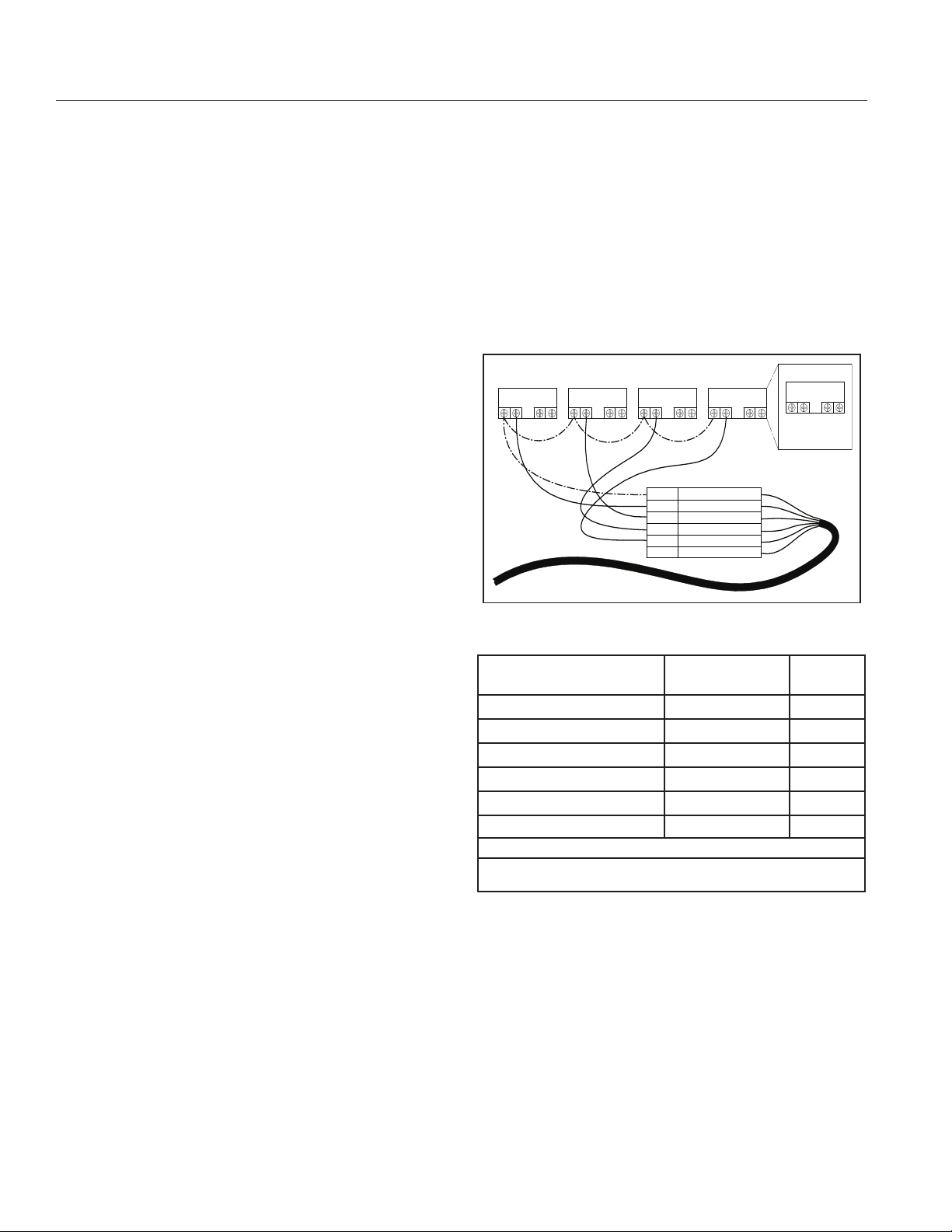
Connecting to External Controls
Using the Supplied Low Voltage Signal for
Digital Control
1. The pump provides a low voltage output signal that
can be used to trigger its own Digital Inputs. This
signal will need to be switched via the External
Control system to engage the PROGRAM it is
connected to (see Figure 12). This could be an
automation relay or switch in another piece of
equipment. This feature could be useful for ensuring
that the pump is running a certain program when
needed to perform a task.
2. The digital input cable included with the External
Control Wiring Kit (Pentair P/N 353129Z) will need
to be cut to length for the installation. Do not leave
excess wire around the installation. The wire should
be supported by something rigid if conduit is not
used.
At one end of the cable is a molded, watertight
connection that plugs into the digital input port on the
side of the drive. The opposite end has 6 wires that
are defined by Table 3 to the right. When using the
+24V signal supplied by the drive, the PROGRAMs
should be wired as shown in Figure 12.
3. When there is a low voltage signal present on the
PROGRAM Digital Input line the pump will run the
settings that are programmed for the PROGRAM
that is being triggered. The +24V signal supplied
via the red wire is the suggested input for the
PROGRAM Digital Inputs. See Figure 12.
Note: Any relay can be associated to any Digital Input.
Figure 12 shows one of many potential wiring options
available to the installer, allowing you to install External
Controls in the way that best suits your needs.
Note: This +24V Signal (red wire) is output from the
drive only, and should never be wired to another
power supply!
WHISPERFLOXF® VS and MAX-E-PROXF® VS Commercial Variable Speed Pump Installation and User’s Guide
Figure 12: External Control Wiring Diagram
Denition Signal Range
24 VDC Output for Digital Inputs * 0 - 20mA Red
PROGRAM 1 Digital Input ** 0, 5 - 30V AC/DC Green
PROGRAM 2 Digital Input 0, 5 - 30V AC/DC Yellow
PROGRAM 3 Digital Input 0, 5 - 30V AC/DC Orange
Quick Clean Digital Input 0, 5 - 30V AC/DC Brown
Common Ground 0V Black
(*) - When operating in ow mode, 24 VDC Output connection will provide owmeter power.
(**) - When operating in ow mode, PROGRAM digital input 1 will be the owmeter signal
connection. PROGRAM digital inputs 2-3 and Quick Clean can be used for scheduling.
Table 3: External Control Wiring Chart
Note: If the pump has been stopped via the Start/Stop
button, the pump will not run until the pump is turned
back on by pressing the Start/Stop button. If the Start/
Stop LED is illuminated, that indicates the pump is on
and will run via Digital Inputs.
Note: When multiple low voltage triggers are present
priority will be: QUICK CLEAN -> PROGRAM 3 ->
PROGRAM 2 -> PROGRAM 1.
Wire
Color
Page 17
13
RELAY
LINE 1
LOAD 1
LOAD 2
LINE 2
POWER RELAY (DPST)
RED
+24V OUTPUT FOR D.I. TRIGGER
GREEN PROGRAM 1 DIGITAL INPUT
YELLOW PROGRAM 2 DIGITAL INPUT
ORANGE PROGRAM 3 DIGITAL INPUT
BROWN
QUICK CLEAN DIGITAL INPUT
BLACK
GROUND
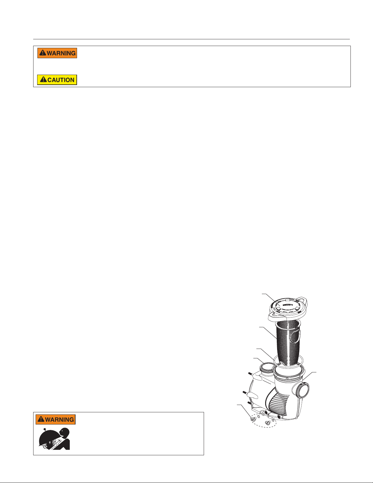
External Control Only Mode
External Control Only mode will only allow the pump
to run from external controls/inputs. When this mode is
active the programmed pump schedule is deactivated,
and user speed requests from the keypad will not be
accepted. If the pump is stopped a user can still program
the speeds for all four PROGRAM buttons.
To activate External Control Only mode:
1. Stop the pump by pressing the Start/Stop button.
2. Activate External Control Only mode by holding the
Start/Stop button for 10 seconds.
3. If successful the LED next to Ext. Control Only will
illuminate. See Figure 13.
4. The Start/Stop button must be pressed again to
allow the pump to run.
To deactivate External Control Only mode:
5. Stop the pump by pressing the Start/Stop button.
6. Deactivate External Control Only mode by holding
the Start/Stop button for 10 seconds.
7. If successful the LED next to Ext. Control Only will
turn off.
8. The Start/Stop button must be pressed again to
allow the pump to run.
Operating the Pump in Flow Mode
When connected to an inline 4-20mA flowmeter, this
pump is capable of maintaining a constant flow based on
the needs of your pool system.
Connecting a flowmeter and operating the pump in flow
mode will require the purchase of:
• External Control Wiring Kit (P/N 353129z)
• A 4-20mA Flowmeter (Pentair recommends P/N
97014-4203KIT)
Flow Mode Setup and Configuration
Before beginning flow mode setup and configuration,
ensure the pool filter has been backwashed and all
pump and skimmer baskets are free of debris.
1. Stop the pump if it is running by pressing the Start/
Stop button.
2. Following the installation instructions given in
the flowmeter’s installation guide, install an inline
4-20mA flowmeter into the plumbing.
3. Using the External Control Wiring Kit, connect the
flowmeter to the digital input port on the side of the
pump drive. See Figure 14.
To Flowmeter
9:00pm
Figure 13: External Control Only Mode
To Digital Inputs
(if desired)
Figure 14: Flowmeter Wiring Diagram
4. Hold the Display button for 3 seconds.
5. Press the Display button three times to access the
Speed or Flow mode selection screen. “Spd” will
display.
6. Use the “+” and “-” arrows to scroll to “Flo”. See
Figure 15.
Note: This option will not be available unless a
4-20mA flowmeter is connected to the pump.
FLo
Figure 15: Setting Flow Mode
7. Press the Display button to access the Flow Mode
High Speed screen.
- Continue to next page -
WHISPERFLOXF® VS and MAX-E-PROXF® VS Commercial Variable Speed Pump Installation and User’s Guide
Page 18
14
Flow Mode Setup and Configuration (cont.)
8. Use the “+” and “-” arrows to set high speed for
flow mode between 2000 and 3450 RPM.
9. Press the Display button. “Press Start” will scroll
across the screen.
10. Press the Start/Stop button and the pump will
ramp up to the programmed maximum speed, then
“Config Flo Sensor” will scroll across the screen.
11. At the flowmeter, configure the flowmeter to values
or within ranges given below:
K Factor: Refer to flowmeter manual
Averaging: 10-30 (20 is recommended)
Sensitivity: Refer to flowmeter manual
4-Set: 0 GPM
20-Set: GPM displayed while pump motor is at
maximum speed set in step 8.
Note: Flowmeter configuration will timeout at the
drive after 10 minutes. If this occurs, repeat steps
4 through 10.
Note: The flowmeter 20-Set will need to be
reconfigured each time the system’s filter is
cleaned.
12. At the pump, press the Display button to continue
through flow mode configuration.
Note: If the pump displays “LoFlo” or “HiFlo” and
a percentage other than “100” (see Figure 16),
adjust 20-set setting at the flowmeter until the
pump displays “100”.
14. Press the Display button. “Auto Tuning” will scroll
across the screen as the pump auto tunes. The
motor will drop to half speed and then slowly ramp
down until the minimum controllable flow is found.
Note: Auto Tuning process will take several
minutes to complete, or much longer in
installations with longer plumbing systems.
15. Motor will stop when Auto Tuning completes. Flow
Mode setup is now complete.
16. Refer to OPERATION section (pages 5-11) to
continue pump programming.
Adjusting Flow Setting
1. Use the “+” and “-” arrows to increase or decrease
the Flow Percentage. This percentage is based on
the high speed set during Flow Mode setup and
configuration.
Example: If flow mode maximum speed is
3000 RPM, lowering flow percentage to “50” will
decrease motor RPMs until the pump is producing
50% of the flow created at 3000 RPM.
LoFL
Figure 16: Low Flow Alarm
13. “Aver” will display (see Figure 17). Use the “+”
and “-” arrows to match the flowmeter’s averaging
value.
88.3
AVEr
Figure 17: Averaging Conguration
WHISPERFLOXF® VS and MAX-E-PROXF® VS Commercial Variable Speed Pump Installation and User’s Guide
Page 19
MAINTENANCE
DO NOT open the strainer pot if pump fails to prime or if pump has been operating without water in the strainer pot. Pumps operated in
these circumstances may experience a build up of vapor pressure and may contain scalding hot water. Opening the pump may cause
serious personal injury. In order to avoid the possibility of personal injury, make sure the suction and discharge valves are open and strainer pot temperature
is cool to touch, then open with extreme caution.
To prevent damage to the pump and for proper operation of the system, clean pump strainer and skimmer baskets regularly.
15
Cleaning the Pump Strainer Basket
The strainer basket, is located in front of the
WhisperFloXF® VS or Max-E-ProXF® VS Commercial
Variable Speed Pump housing. The strainer basket must
be kept clean and free of debris. Inspect basket through
the lid on the top of the housing. Be sure to visually
inspect the strainer basket at least once a week. Dirty
strainer baskets reduce filter and heater efficiency and
put abnormal stress on the pump motor.
1. Press Start/Stop to stop the pump and disconnect
power to the pump at the main circuit breaker.
2. Relieve pressure in the system.
3. Turn the lid and locking ring counter-clockwise and
remove from the pump.
4. Remove debris and rinse out the basket. Replace
the basket if it is cracked.
5. Put the basket back into the housing. Be sure to
align the rib on the basket with the notch in the
volute.
6. Fill the pump pot and volute up to the inlet port with
water.
7. Clean the lid and locking ring, O-ring, and sealing
surface of the pump pot.
Note: It is important to keep the lid O-ring clean and
well lubricated.
8. Reinstall the lid by placing the locking ring and lid
on the pot. Be sure the lid O-ring is properly placed.
Seat the locking ring and lid on the pump then
turn clockwise until the locking ring handles are
horizontal.
Note: Ensure that the side of the lid/locking ring
marked “Front” is positioned at the front of the pump.
9. Return power to the pump at the circuit breaker.
10. Open the manual air relief valve on the top of the
filter. Stand clear of the filter.
11. Wait until all pressure is relieved. Start the pump.
12. Bleed air from the filter until a steady stream of
water comes out of the filter air relief valve. Close
the manual air relief valve.
Winterizing
You are responsible for determining when freezing
conditions may occur. If freezing conditions are
expected, take the following steps to reduce the risk of
freeze damage. Freeze damage is not covered under
warranty.
To prevent freeze damage, follow the procedures
below:
1. Press the Start/Stop button to stop the pump and
shut off electrical power for the pump at the circuit
breaker.
2. Drain the water out of the pump housing by
removing the two thumb-twist drain plugs from the
housing. Store the plugs in the pump basket.
3. Cover the motor to protect it from severe rain, snow
and ice.
Note: Do not wrap motor with plastic or other air tight
materials during winter storage. The motor may be
covered during a storm, winter storage, etc., but never
when operating or expecting operation.
Note: In mild climate areas, when temporary freezing
conditions may occur, run your filtering equipment all
night to prevent freezing.
Lid/Locking Ring
Strainer
Basket
O-Ring
Volute
Pot
Drain
Plugs
THIS SYSTEM OPERATES UNDER HIGH PRESSURE. When
any part of the circulating system (e.g., Lock Ring, Pump, Filter,
Valves, etc.) is serviced, air can enter the system and become
pressurized. Pressurized air can cause the lid to separate
which can result in serious injury, death, or property damage.
To avoid this potential hazard, follow above instructions.
WHISPERFLOXF® VS and MAX-E-PROXF® VS Commercial Variable Speed Pump Installation and User’s Guide
Strainer Pot Assembly
Page 20
16
SERVICING
Always disconnect power to the WhisperFloXF® VS or Max-E-ProXF® VS Commercial Variable Speed Pump at the circuit breaker and disconnect
the digital input cable before servicing the pump. Failure to do so could result in death or serious injury to service people, users or others due
to electric shock. Read all servicing instructions before working on the pump.
DO NOT open the strainer pot if pump fails to prime or if pump has been operating without water in the strainer pot. Pumps operated in these
circumstances may experience a build up of vapor pressure and may contain scalding hot water. Opening the pump may cause serious personal
injury. In order to avoid the possibility of personal injury, make sure the suction and discharge valves are open and strainer pot temperature is cool to touch, then
open with extreme caution.
Be sure not to scratch or mar the polished shaft seal faces; seal will leak if faces are damaged. The polished and lapped faces of the seal could
be damaged if not handled with care.
Motor and Drive Care
Protect from heat
1. Shade the motor from the sun.
2. Any enclosure must be well ventilated to prevent
overheating.
3. Provide ample cross ventilation.
Protect against dirt
1. Protect from any foreign matter.
2. Do not store (or spill) chemicals on or near the motor.
3. Avoid sweeping or stirring up dust near the motor
while it is operating.
4. If a motor has been damaged by dirt it may void the
motor warranty.
5. Clean the lid and locking ring O-ring, and sealing
surface of the pump pot.
Protect against moisture
1. Protect from continuous splashing or continuous
sprayed water.
2. Protect from extreme weather such as flooding.
3. If motor internals have become wet - let them dry
before operating. Do not allow the pump to operate if it
has been flooded.
4. If a motor has been damaged by water it may void
the motor warranty.
The Mechanical Seal
The mechanical seal consists primarily of two parts, a
rotating ceramic seal housed in the impeller and a stationary
spring seal in the sealplate. The pump requires little or no
service other than reasonable care. A mechanical seal may
occasionally become damaged and must be replaced.
Ceramic &
Spring Half:
Carbon face is
pointing outward
Mechanical Seal
Rubber Half:
White ceramic face
is pointing outward
Pump Disassembly
Tools required:
• 1/4-inch Hex Allen wrench
• T20 Star-head Driver
• 9/16-inch wrench
• 3/4-inch socket wrench
• 9/64-inch Hex key wrench
To remove and repair the motor assembly, follow the
steps below:
1. Turn off the pump circuit breaker at the main panel.
2. Drain the pump by removing the drain plugs.
3. Disconnect any digital inputs rom the pump (if connected).
4. Remove the four (4) star-head screws from the top of the
drive cover.
5. Disconnect the drive cover from the drive and set it to the
side in a safe place.
6. Remove the four (4) star-head screws securing the drive to
the motor. Two (2) screws are located under the drive and
two (2) are located inside the drive.
7. Remove the drive by lifting upwards to separate it from the
motor.
8. Using a 9/16-inch wrench, remove the six (6) nuts securing
the volute to the seal plate/motor assembly.
9. Gently pull the two pump halves apart.
10. Using a 9/64-inch hex key wrench, remove the three (3)
screws securing the diffuser to the seal plate.
11. Hold the impeller securely in place by hand. Remove the
impeller lock screw located at the center of the impeller,
using a deep well 3/4-inch socket and wrench. The screw is
a left-handed thread and loosens in a clockwise direction.
Remove the impeller screw o-ring. Inspect the o-ring for
damage, cracks etc. Replace if damaged.
The pump impeller may have sharp edges that
could potentially cut or scratch the user’s hands.
Pentair recommends that safety gloves be worn when holding the
impeller during disassembly and reassembly.
12. Using the 1/4-inch Allen wrench to hold the motor shaft, twist
the impeller counter-clockwise to remove it from the shaft.
13. Using a 9/16-inch wrench, remove the four (4) nuts
securing the seal plate to the motor.
14. Place the seal plate face down on a flat surface and press
out the ceramic part of the mechanical seal.
15. Clean the seal plate, seal housing, and the motor shaft.
Pump illustrated parts view on the next page
WHISPERFLOXF® VS and MAX-E-PROXF® VS Commercial Variable Speed Pump Installation and User’s Guide
Page 21
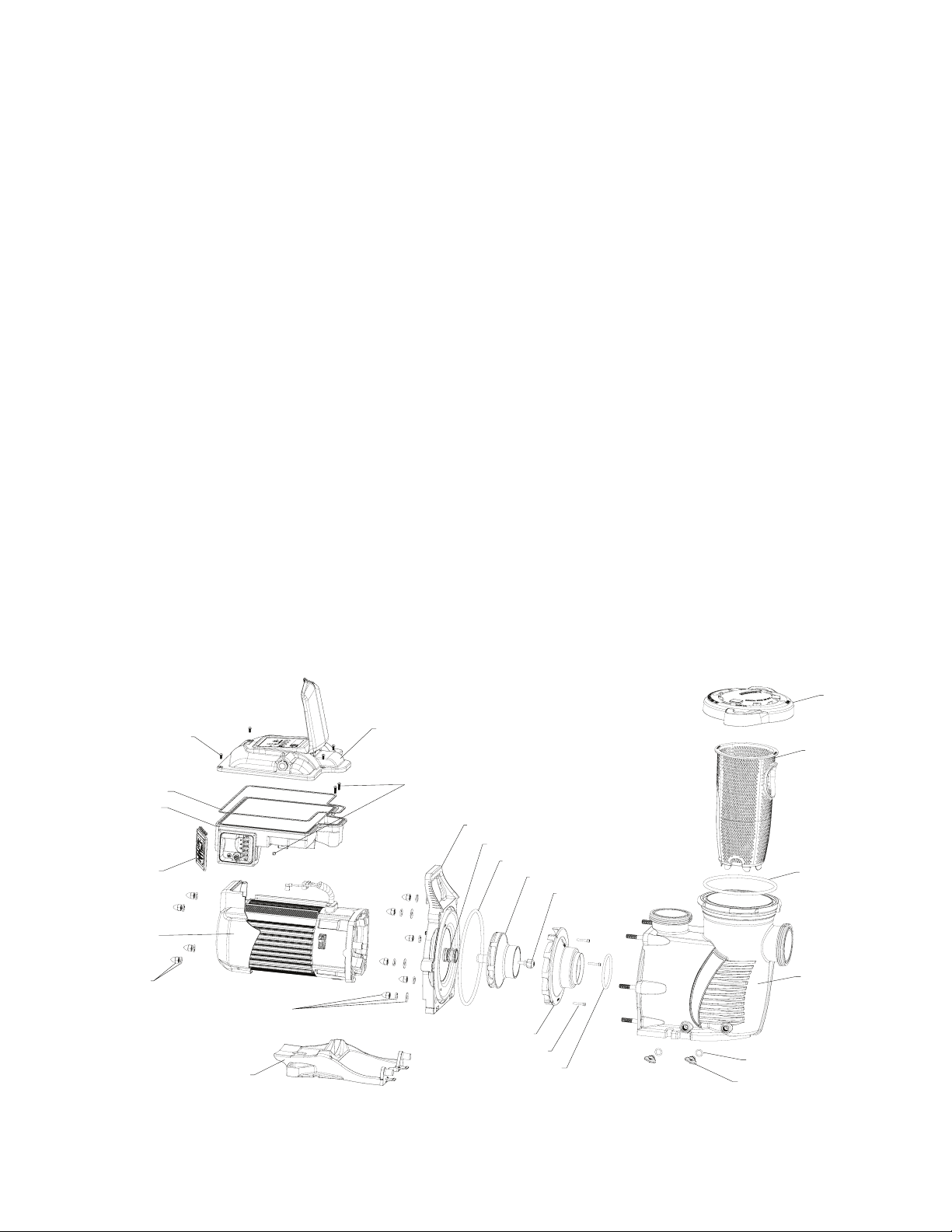
Pump Reassembly/Seal Replacement
LOCKING RING/LID
DRAIN PLUG
MOTOR NUT AN
1. Install the spring end of the mechanical seal onto the impeller
shaft. Be sure black/carbon face is facing outward.
2. Remount the seal plate to the motor using the four (4) motor
nuts and washers.
3. With the white ceramic face facing outward, press the seal into
the seal plate with your thumbs and wipe off the ceramic with a
clean cloth. Do not lubricate seal faces.
4. Hand tighten impeller onto the motor shaft.
5. Screw in the impeller reverse lock screw (counter-clockwise to
tighten).
6. Remount the diffuser onto the seal plate. Make sure the
plastic pins and holding screw inserts are aligned (see “TOP”
indicator).
Note: Ensure that the seal plate o-ring is clean and free of
debris.
7. Assemble the motor subassembly to the housing. Do not
tighten the nuts and washers until all four (4) motor nuts are
in place. Using a torque wrench, install and tighten the six (6)
seal plate nuts and washers to a torque value of 100 in-lbs
(maximum). Do not overtighten the nuts.
8. Reinstall the drive onto the top of the motor.
9. Fill the WhisperFloXF® VS or Max-E-ProXF® VS Commercial
Variable Speed Pump with water.
10. Reinstall the pump lid and locking ring; see “Cleaning the
Pump Strainer Basket” on page 15.
11. Prime the system. See page 7 for priming instructions.
17
DRIVE COVER
SCREWS (4X)
DRIVE GASKET
DRIVE
WIRING COVER
AND SCREWS
MOTOR
WASHER (4X)
D
SEAL PLATE NUT
AND WASHERS (6X)
FOOT
DRIVE COVER
DRIVE TO MOTOR
SCREWS (4X)
SEAL PLATE
MECHANICAL SEAL
SEAL PLATE O-RING
IMPELLER
IMPELLER SET SCREW
DIFFUSER
DIFFUSER SCREWS (3X)
DIFFUSER O-RING
Pump Illustrated Parts View
STRAINER BASKET
LID O-RING
VOLUTE
DRAIN PLUG O-RING (2X)
WHISPERFLOXF® VS and MAX-E-PROXF® VS Commercial Variable Speed Pump Installation and User’s Guide
Page 22
18
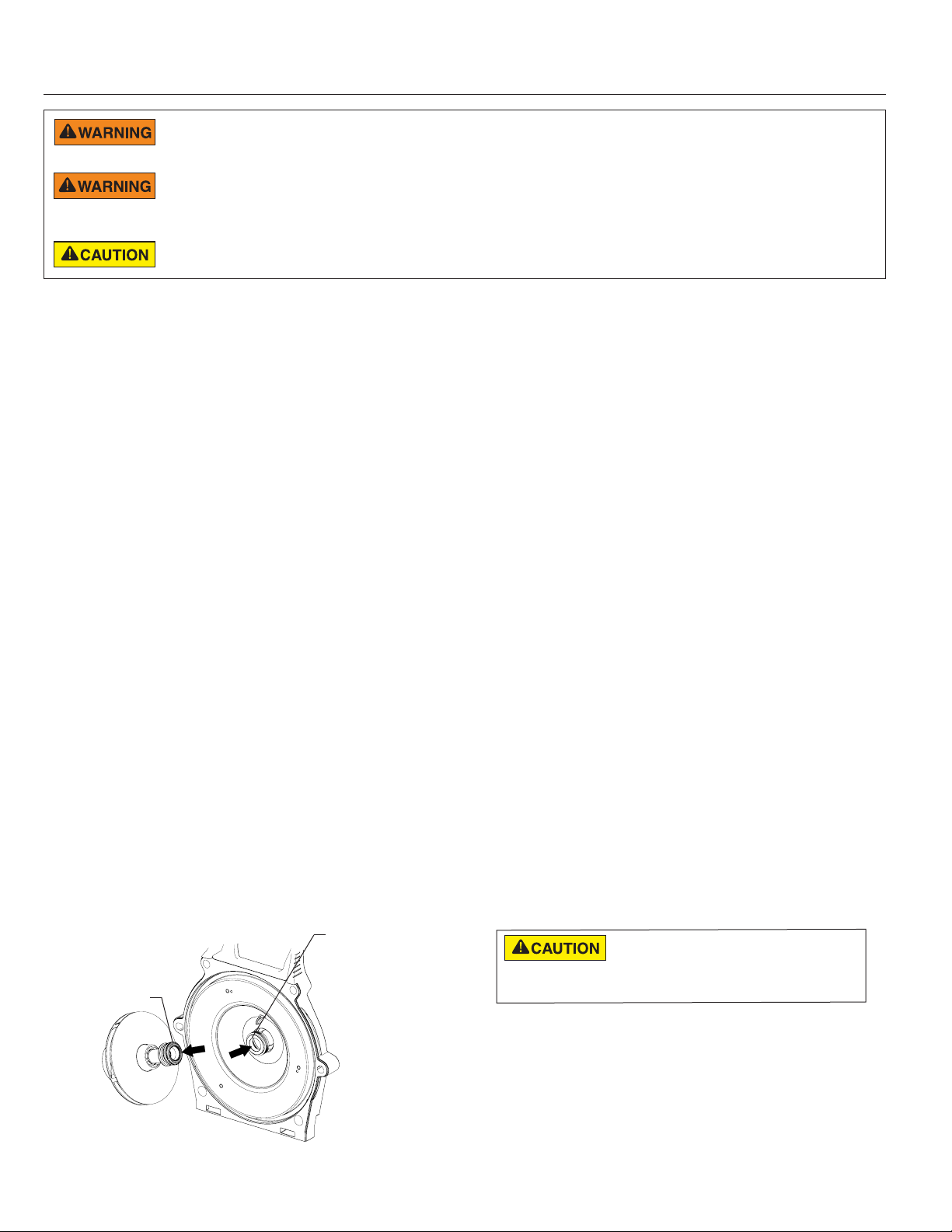
Removing and Replacing the Drive Assembly
Removing the Existing Drive Assembly:
1. If possible, record your programmed schedule and priming speed before proceeding.
2. Disconnect power to the pump at the
circuit breaker. Wait five (5) minutes after
disconnecting the power before removing
the drive cover.
3. Using a #2 Phillips-head screwdriver, uninstall
the field wiring compartment cover from the
side of the drive. Place the cover and all screws
aside.
4. Uninstall field wiring, strain relief and/or conduit
from the drive.
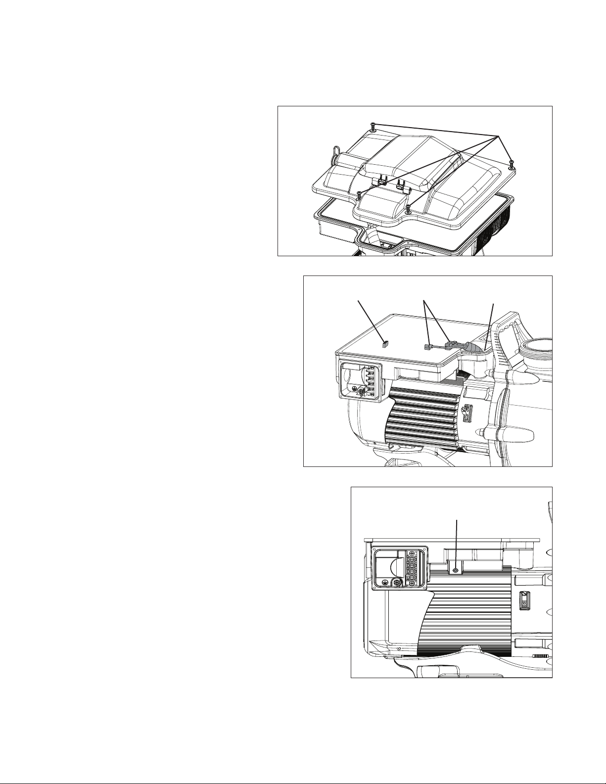
5. Using a T20 star-head screwdriver, remove the
four (4) Drive Cover Screws (Figure 18).
6. Gently lift the drive cover and disconnect the
keypad cable from the Keypad Terminal (Figure
19). Place the drive cover aside.
7. Carefully disconnect the four (4) white Motor
Connections (Figure 19) from their flag terminals.
Note: Take note of which flag terminal each cable is
paired with. Each connector must be installed to the
same flag terminal when installing the new drive.
8. Using a T20 star-head screwdriver, remove the two
(2) Front Drive-to-Motor Screws (Figure 19).
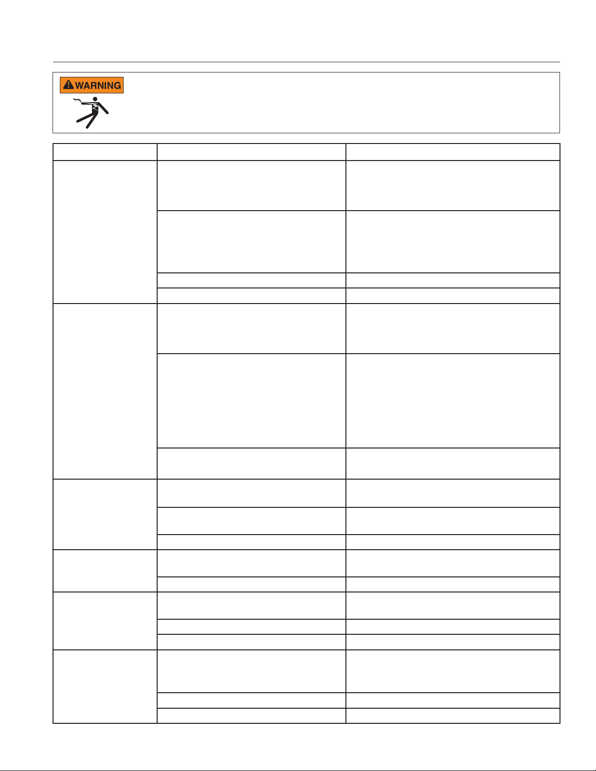
9. Using a T20 star-head screwdriver, remove the two
(2) Rear Drive-to-Motor Screws (Figure 20) from
underneath the drive.
10. Lift the drive away from the motor, carefully guiding
the motor cables through the opening in the front of
the drive. Place the old drive aside.
Figure 18
Figure 19
Keypad
Terminal
Motor
Connections
Drive Cover
Screws (x4)
Front Drive-to-Motor
Screws (x2) (Not Shown)
Installing the New Drive Assembly:
11. Place the new drive onto the motor, carefully feeding the Motor
Connectors through the opening in the front of the drive.
12. Reinstall the four (4) Drive-to-Motor Screws (Figures 19 and
20).
13. Referring back to the notes taken in Step 7, plug each motor
cable into its corresponding flag terminal.
14. Reconnect the drive cover’s keypad connector to the drive and
seat the drive cover onto the drive body.
15. Reinstall the four (4) Drive Cover Screws (Figure 18).
16. Reconnect the Main Power supply and strain relief or conduit for
the electrical wires.
17. Reinstall the field wiring compartment cover using the four (4)
cover screws.
18. Return power to the pump at the circuit breaker.
19. Your pump’s time, schedule and priming speed will need
to be reprogrammed. Refer to the OPERATION section for
programming procedures.
WHISPERFLOXF® VS and MAX-E-PROXF® VS Commercial Variable Speed Pump Installation and User’s Guide
Figure 20
Rear Drive-to-Motor
Screws (x2)
Page 23
TROUBLESHOOTING
Always disconnect power to the pump at the circuit breaker and disconnect the digital input cable before servicing the pump. Failure
to do so could result in death or serious injury to serviceman, pool users or others due to electric shock. DO NOT attempt to adjust or
service without consulting your dealer or a qualified pool technician. Read the entire Installation & User’s Guide before attempting to
use, service, or adjust the pool filtering system or heater.
Problem Possible Cause Corrective Action
Pump failure.
Reduced capacity
and/or head.
Pump fails to start.
Pump runs then stops.
Pump is noisy.
Inadequate circulation.
Pump will not prime - Air leak in suction. Check suction piping and valve glands on any suction
gate valves. Secure lid on pump strainer pot and be
sure lid gasket is in place. Check water level to be sure
skimmer is not drawing air.
Pump will not prime - Not enough water. Be sure the suction lines, pump, strainer, and pump
volute are full of water. Be sure valve on suction line is
working and open (some systems do not have valves).
Check water level to make sure water is available through
skimmer.
Pump stainer basket is clogged. Clean pump strainer basket.
Pump strainer gasket is defective. Replace gasket.
Air pockets or leaks in suction line.
Clogged impeller. Turn off electrical power to the pump.
Pump strainer basket clogged. Clean suction trap.
Main voltage is not present. 1. Replace fuse, reset breaker/GFCI.
Pump shaft is locked. Check if the pump can be rotated by hand and remove
Pump shaft is damaged. Replace pump.
“0004” over-temperature alarm. Check that back of pump is free from dirt and debris. Use
“0017” over-current alarm. Inspect drive to motor connection terminals.
Debris in contact with fan. Check that back of pump is free from dirt and debris. Use
Debris in strainer basket. Clean pump strainer basket.
Loose mounting. Check that mounting bolts of pump and pump are tight.
Filter or pump basket dirty. Check pump strainer basket; if logged, turn pump off and
Suction/discharge piping is too small. Increase piping size.
Speed is set too slow for proper filtration cycle. Increase filtration run time.
Check suction piping and valve glands on any
suction gate valves. Secure lid on pump strainer pot and
be sure lid gasket is in place. Check water level to be sure
skimmer is not drawing air.
Disassemble (see page 16, ‘Pump Disassembly’)
Clean debris from impeller. If debris cannot be removed,
complete the following steps:
1. Remove left hand thread anti-spin bolt and o-ring.
2. Remove, clean, and reinstall impeller.
3. Reassemble (see page 17, ‘Pump Reassembly’)
Clean pump strainer basket.
2. Tighten main wire connections.
any blockage.
compressed air to clean.
compressed air to clean.
clean basket.
Check and clean pool filter.
19
WHISPERFLOXF® VS and MAX-E-PROXF® VS Commercial Variable Speed Pump Installation and User’s Guide
Page 24

20
Troubleshooting, (continued)
Problem Possible Cause Corrective Action
Pump runs without flow.
“LoFlo” or “HiFlo” alarm.
Electrical problem.
Mechanical troubles and
noise.
Pump does not respond to
external controls.
Impeller is loose. Check that pump is spinning by looking at fan on back of
motor. If so, check that pump impeller is correctly installed.
Air leak. Check plumbing connections and verify they are tight.
Clogged or restricted plumbing or strainer basket. Check for blockage in strainer basket or suction side
piping.
Check for blockage in discharge piping, including partially
closed valve or dirty pool filter.
Flowmeter 20-set setting is too high (Low Flow
alarm) or too low (High Flow alarm).
Could appear as a “000E” low voltage alarm. Check voltage at motor terminals and at panel while pump
Could appear as “0017” overheat alert. Check line voltage; if less than 90% or more than 110% of
The pump motor is running but with loud noise. If suction and discharge piping are not adequately
Foreign matter (gravel, metal, etc.) in
pump impeller.
Cavitation. Improve suction conditions.
Speaking noise, especially evident at pump startup or slow down.
Improper external control, digital input or flow
control setup.
Clean the pool filter, pump strainer basket and all skimmer
baskets. Recalibrate the flowmeter 20-set (refer to page 14
and/or flowmeter manual).
is running. If low, see wiring instructions or consult power
company.
Check for loose connections.
rated voltage consult a licensed electrician.
Increase ventilation.
Reduce ambient temperature.
Inspect drive to motor connection terminals.
Motor runs too hot. Turn power to motor off.
Check for proper voltage.
Check for proper impeller or impeller rubbing.
supported, pump assembly will be strained. Do not mount
pump on a wooden platform! Securely mount on concrete
platform for quietest performance.
Disassemble pump, clean impeller, follow pump service
instructions for reassembly.
Increase pipe size.
Decrease number of fittings.
Increase discharge pressure.
Inspect motor slinger and motor shaft seal behind
the slinger (NOT the pump’s mechanical seal). Apply
lubrication to the motor shaft rubber seals.
Be sure that the digit input cable is connected at both ends.
WHISPERFLOXF® VS and MAX-E-PROXF® VS Commercial Variable Speed Pump Installation and User’s Guide
Page 25

Faults and Alarms
If an alarm is triggered the drive’s LCD screen will display the fault code text and the WhisperFloXF® VS or
Max-E-ProXF® VS Commercial Variable Speed Pump will stop running. Disconnect power to the pump and wait until
the keypad LEDs have all turned off. At this point, reconnect power to the pump. If the error has not cleared then
proper troubleshooting will be required. Use the error description table below to begin troubleshooting.
FAULT CODE DESCRIPTION
000a
000b
000C
000D
000E
000F
001A
0002
0004
0006
0008
0010
0011
0012
0013
0014
0015
0016
0017
0018
0019
0021
Absolute L4 inductor temperature limit exceeded
DC bus over voltage detected
DC bus under voltage detected
Absolute AC line over voltage detected
Absolute AC line under voltage detected
Internal voltage ref out of range
Input bypass relay fault detected
Absolute phase current limit exceeded
Absolute Power Module temperature limit exceeded
Absolute Power Factor Correction (PFC) temperature limit exceeded
Absolute Diode Bridge temperature limit exceeded
External voltage ref out of range
Module therm out of range
PFC therm out of range
Bridge therm out of range
L4 Inductor therm out of range
Current offset out of range
Motor start fault detected
Power module over current detected
3 phase current imbalance detected
Module fault test failure
Communication link between HMI and motor control has been lost
21
0021 – Communication Link between the HMI and Motor control has been lost: Check the jacketed wire on
the back side of the keypad inside the drive top cover. Ensure that the 5 pin connector is properly plugged into the
socket and that there is no damage to the cable.
0017 – Power Module over current detected: If this error displays multiple times, then there may be a problem
with the pump’s rotating assembly. Please disassemble the pump and investigate to see if there is a problem with the
impeller or mechanical seal. See page 16 “Pump Disassembly” for instructions for disassembling the pump.
000e – Absolute AC Under Voltage Detected: This indicates that the supply voltage has dropped below the
operating range of 187v. This could be caused by normal voltage variation and will clear itself. Otherwise there could
be excess voltage sag caused by improper installation or improper supply voltage.
WHISPERFLOXF® VS and MAX-E-PROXF® VS Commercial Variable Speed Pump Installation and User’s Guide
Page 26

22
7
REPLACEMENT PARTS
2
6
1
21
22
5
4
3
12
11
10
13
9
Replacement Parts List
Item
No.
Description
1 Drive Kit* 358085 358086
2 Top Cover Kit w/ Screws 358093 358094
3 Motor w/ Fan Shroud 358089 358090
4 Fan Shroud w/ Screws 358095 358096
5 Field Wiring Cover w/ Screws 358091 358092
6 Motor/Drive Assembly 358079s 358080s
7 Wet End Assembly 400000 401000
8 Union Kit 410020
9 Motor Base 400004Z 401004Z
10 Acorn Nut (Qty. 10) 071413
11 Lock Washer (Qty. 10) U43-12SS
12 Flat Washer (Qty. 6) 072184
13 Seal Plate 400002 401002
14 Mechanical Seal 17351-0101S
15 Seal Plate O-Ring 351446
16 Impeller 400023
17 Impeller Set Screw 37337-6080
WhisperFloXF VS
Part #
Max-E-
ProXF VS
Part #
19 20
1817161514
Item
No.
29
28
Description
23
24
WhisperFloXF VS
Part #
25
27
18 Diffuser 400011
19 Diffuser Screws 353323
20 Diffuser O-Ring 350336
21 Lid/Locking Ring Assembly 400006 401006
22 Strainer Basket 400007Z
23 Lid/Locking Ring O-Ring 35505-1440
24
2.5” C-Clip Locking Ring (Qty. 2)
410001
25 2.5” Union Nut (Qty. 2) 411000
26
2.5” Union Adapter w/o Tap
(Qty. 2)
410002
27 2.5” Diamond Seal Kit (Qty. 2) 410016Z
28 Drain Plug O-Ring (Qty. 2) 192115
29 Drain Plug (Qty. 2) 071131 357161
- External Control Wiring Kit 353129Z
- 3-inch Flowmeter Kit 97014-4203KIT
(-) Not Shown
26
Max-E-
ProXF VS
Part #
8
*NOTE: Drive Kit includes drive, top cover, keypad cover and field wiring cover/screws.
WHISPERFLOXF® VS and MAX-E-PROXF® VS Commercial Variable Speed Pump Installation and User’s Guide
Page 27

Performance Curves
0
10
20
30
40
50
60
70
80
90
0102030405060708090 100 110120 130140 150160 170180 190200 210220 230240 250260 270280
Total Dynamic Head in Ft of H2O
Volumetric Flow Rate in GPM
PROGRAM 1
1720 RPM
PROGRAM 2
2500 RPM
PROGRAM 3
3000 RPM
QUICK CLEAN
3450 RPM
(14.1”)
35.8cm
(9.1”)
23.1cm
(11”)
27.9cm
(12.9”)
32.8cm
(11.9”)
30.2cm
(15.6”)
39.6cm
(11.4”)
29cm
(6.6”)
16.8cm
(6.4”)
16.3cm
(10.4”)
26.4cm
(10.2”)
25.9cm
(6.5”)
16.5cm
23
TECHNICAL DATA
Pump Dimensions
Mechanical Specifications
300-3450 RPM
5
Storage: -40˚F - 185˚F (-40˚C - 85˚C)
Operating: 32˚F - 122˚F (0˚C - 50˚C)
Humidity: Relative 0 to 95% non-condensing
Speed Range
Maximum Continuous
Load (Total HP)
Ambient Conditions
Electrical Specifications
Voltage
Max Amps
WEF / THP
Frequency
1PH: 208-230/277-460V
3PH: 208-460V
1PH: 20-21/17-11A
3PH: 13-6A
WEF 5.0 THP 5.0
50/60 Hz
WHISPERFLOXF® VS and MAX-E-PROXF® VS Commercial Variable Speed Pump Installation and User’s Guide
Page 28

1620 HAWKINS AVE., SANFORD, NC 27330 • (919) 566-8000
*358077*
10951 WEST LOS ANGELES AVE., MOORPARK, CA 93021 • (805) 553-5000
WWW.PENTAIR.COM
All Pentair trademarks and logos are owned by Pentair or one of its global aliates. Sta-Rite®, WhisperFloXF® and Max-E-ProXF® are trademarks and/or
registered trademarks of Pentair Water Pool and Spa, Inc. and/or its aliated companies in the United States and/ or other countries. Unless expressly
noted, names and brands of third parties that may be used in this document are not used to indicate an aliation or endorsement between the owners
of these names and brands and Pentair Water Pool and Spa, Inc. Those names and brands may be the trademarks or registered trademarks of those third
parties. Because we are continuously improving our products and services, Pentair reserves the right to change specications without prior notice.
Pentair is an equal opportunity employer.
© 2019 Pentair Water Pool and Spa, Inc. All rights reserved. This document is subject to change without notice.
P/N 358077 REV. A 5/16/19
 Loading...