

®
WHISPERFLO
HIGH PERFORMANCE PUMP
ENGLISH 1 ESPAÑOL 10
INSTALLATION AND
USER’S GUIDE
IMPORTANT SAFETY INSTRUCTIONS
READ AND FOLLOW ALL INSTRUCTIONS
SAVE THESE INSTRUCTIONS
WHISPERFLO
®
High Performance Pump Installation and User’s Guide

i
CUSTOMER SERVICE / TECHNICAL SUPPORT
If you have questions about ordering Pentair Aquatic Systems replacement parts, and pool products, please contact:
Customer Service and Technical Support, USA
(8 A.M. to 4:30 P.M. — Eastern/Pacific Times)
Phone: (800) 831-7133
Fax: (800) 284-4151
Web site
Visit www.pentairpool.com or www.staritepool.com
TABLE OF CONTENTS
Important Pump Warning and
Safety Instructions ................................................
Installation ..............................................................
Location
Piping
Fittings and Valves
Electrical Wiring Installation
Wiring
Grounding
Bonding
Maintenance ...........................................................
Pump Strainer Basket
Cleaning the Pump Strainer Basket
Winterizing
Sanford, North Carolina (8 A.M. to 4:30 P.M. ET)
Phone: (919) 566-8000
Fax: (919) 566-8920
Moorpark, California (8 A.M. to 4:30 P.M. PT)
Phone: (805) 553-5000 (Ext. 5591)
Fax: (805) 553-5515
Servicing .................................................................
ii
1
1
1
1
2
2
2
2
3
3
3
Motor Care
Shaft Seal Replacement
Pump Disassembly
Pump Reassembly
Restart Instructions
Priming the Pump
Troubleshooting .....................................................
Replacement Parts .................................................
Illustrated Parts List
Pump Performance Curves
Español Tabla de Contenidos ................................
3
4
4
4
4
5
5
5
6
7
7
9
11
© 2018 Pentair Water Pool and Spa, Inc. All rights reserved. This document is subject to change without notice.
1620 Hawkins Ave., Sanford, NC 27330 • (919) 566-8000
10951 West Los Angeles Ave., Moorpark, CA 93021 • (805) 553-5000
All Pentair trademarks and logos are owned by Pentair or one of its global affiliates. WhisperFlo® and High Flow™ are trademarks
and/or registered trademarks of Pentair Water Pool and Spa, Inc. and/or its affiliated companies in the United States and/ or other
countries. Unless expressly noted, names and brands of third parties that may be used in this document are not used to indicate an
affiliation or endorsement between the owners of these names and brands and Pentair Water Pool and Spa, Inc. Those names and
brands may be the trademarks or registered trademarks of those third parties. Because we are continuously improving our products
and services, Pentair reserves the right to change specifications without prior notice. Pentair is an equal opportunity employer.
P/N 071109 Rev. L 6/28/18
WHISPERFLO
®
High Performance Pump Installation and User’s Guide
IMPORTANT PUMP WARNING AND SAFETY INSTRUCTIONS
F
IMPORTANT NOTICE
This guide provides installation and operation instructions for this pump.
Consult Pentair with any questions regarding this equipment.
Attention Installer: This guide contains important information about the
installation, operation and safe use of this product. This information should
be given to the owner and/or operator of this equipment after installation
or left on or near the pump.
Attention User: This manual contains important information that will help
you in operating and maintaining this product. Please retain it for future
reference.
READ AND FOLLOW ALL INSTRUCTIONS
SAVE THESE INSTRUCTIONS
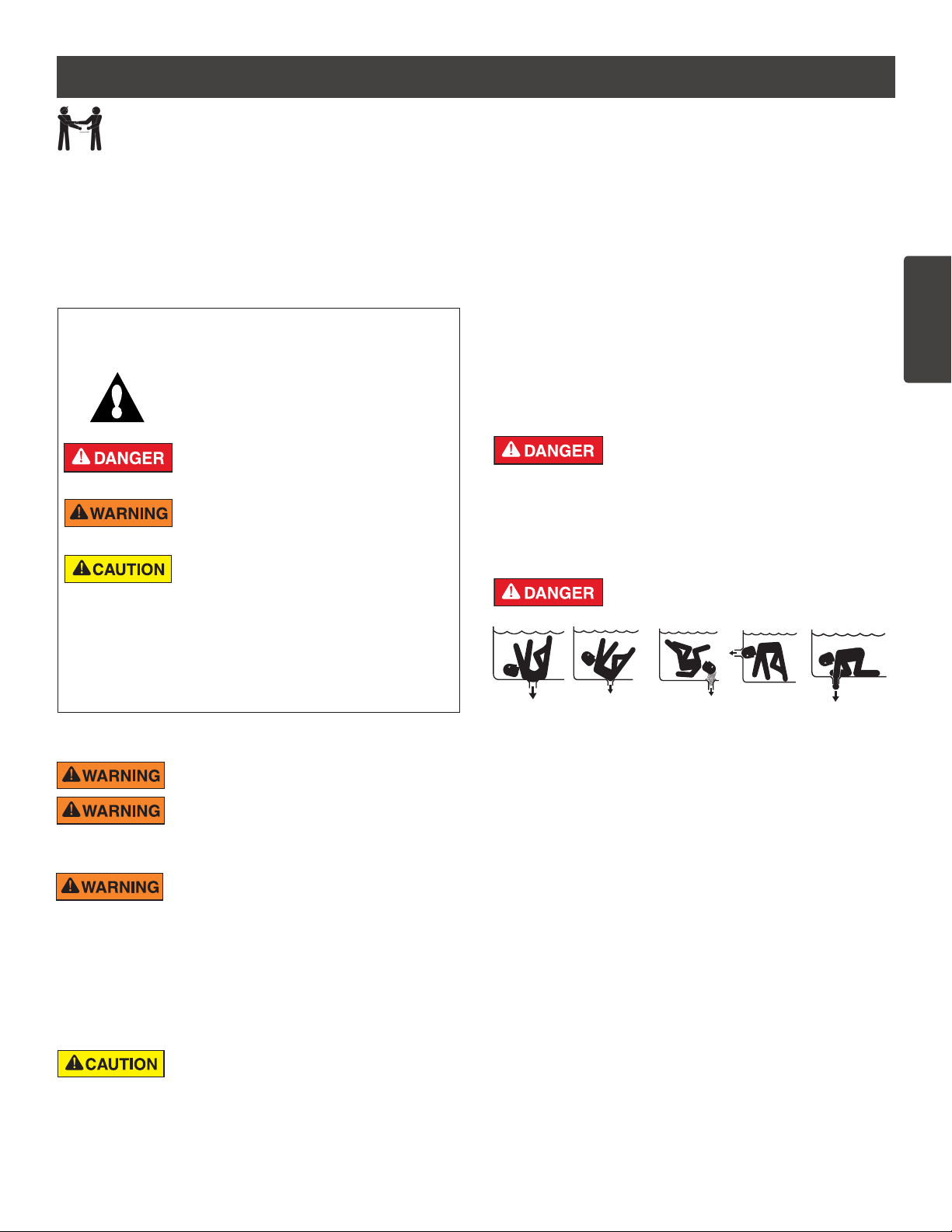
This is the safety alert symbol. When you see this
symbol on your system or in this manual, look for
one of the following signal words and be alert to
the potential for personal injury.
Warns about hazards that can cause death,
serious personal injury, or major property damage
if ignored.
Warns about hazards that may cause death,
serious personal injury, or major property damage
if ignored.
Warns about hazards that may or can cause minor
personal injury or property damage
if ignored.
NOTE Indicates special instructions not related to
hazards.
Carefully read and follow all safety instructions in this manual and on
equipment. Keep safety labels in good condition; replace if missing
or damaged.
When installing and using this electrical equipment, basic safety
precautions should always be followed, include the following:
Do not permit children to use this product.
RISK OF ELECTRICAL SHOCK. Connect only to
a branch circuit protected by a ground-fault circuitinterrupter (GFCI). Contact a qualified electrician if you cannot verify that
the circuit is protected by a GFCI.
This unit must be connected only to a supply circuit
that is protected by a ground-fault circuit-interrupter
(GFCI). Such a GFCI should be provided by the installer and should
be tested on a routine basis. To test the GFCI, push the test button.
The GFCI should interrupt power. Push the reset button. Power should
be restored. If the GFCI fails to operate in this manner, the GFCI is
defective. If the GFCI interrupts power to the pump without the test button
being pushed, a ground current is flowing, indicating the possibility of an
electric shock. Do not use this pump. Disconnect the pump and have the
problem corrected by a qualified service representative before using.
This pump is for use with permanent swimming
pools and may also be used with hot tubs and spas
if so marked. Do not use with storable pools. A permanently-installed pool
is constructed in or on the ground or in a building such that it cannot be
readily disassembled for storage. A storable pool is constructed so that
it is capable of being readily disassembled for storage and reassembled
to its original integrity.
General Warnings
• Never open the inside of the drive motor enclosure. There is a
capacitor bank that holds a 230 VAC charge even when there is no
power to the unit.
• The pump is not submersible.
• The pump is capable of high flow rates; use caution when installing
and programming to limit pumps performance potential with old or
questionable equipment.
• Code requirements for electrical connection differ from country to
country, state to state, as well as local municipalities. Install equipment
in accordance with the National Electrical Code and all applicable
local codes and ordinances.
• Before servicing the pump; switch OFF power to the pump by
disconnecting the main circuit to the pump.
• This appliance is not intended for use by persons (including children) of
reduced physical, sensory or mental capabilities, or lack of experience
and knowledge, unless they have been given supervision or instruction
concerning the use of the appliance by a person responsible for their
safety.
FAILURE TO FOLLOW ALL INSTRUCTIONS AND
WARNINGS CAN RESULT IN SERIOUS BODILY
INJURY OR DEATH. THIS PUMP SHOULD BE INSTALLED AND
SERVICED ONLY BY A QUALIFIED POOL SERVICE PROFESSIONAL.
INSTALLERS, POOL OPERATORS AND OWNERS MUST READ
THESE WARNINGS AND ALL INSTRUCTIONS IN THE OWNER’S
MANUAL BEFORE USING THIS PUMP. THESE WARNINGS AND
THE OWNER’S MANUAL MUST BE LEFT WITH THE POOL OWNER.
SUCTION ENTRAPMENT HAZARD: STAY OFF
THE MAIN DRAIN AND AWAY FROM ALL SUCTION
OUTLETS!
THIS PUMP PRODUCES HIGH LEVELS OF SUCTION AND CREATES
A STRONG VACUUM AT THE MAIN DRAIN AT THE BOTTOM OF THE
BODY OF WATER. THIS SUCTION IS SO STRONG THAT IT CAN TRAP
ADULTS OR CHILDREN UNDER WATER IF THEY COME IN CLOSE
PROXIMITY TO A DRAIN OR A LOOSE OR BROKEN DRAIN COVER
OR GRATE.
THE USE OF UNAPPROVED COVERS OR ALLOWING USE OF
THE POOL OR SPA WHEN COVERS ARE MISSING, CRACKED OR
BROKEN CAN RESULT IN BODY OR LIMB ENTRAPMENT, HAIR
ENTANGLEMENT, BODY ENTRAPMENT, EVISCERATION AND/OR
DEATH.
The suction at a drain or outlet can cause:
Limb Entrapment: When a limb is sucked or inserted into an opening
resulting in a mechanical bind or swelling. This hazard is present when
a drain cover is missing, broken, loose, cracked or not properly secured.
Hair Entanglement: When the hair tangles or knots in the drain cover,
trapping the swimmer underwater. This hazard is present when the flow
rating of the cover is too small for the pump or pumps.
Body Entrapment: When a portion of the body is held against the drain
cover trapping the swimmer underwater. This hazard is present when the
drain cover is missing, broken or the cover flow rating is not high enough
for the pump or pumps.
Evisceration/Disembowelment: When a person sits on an open pool
(particularly a child wading pool) or spa outlet and suction is applied directly
to the intestines, causing severe intestinal damage. This hazard is present
when the drain cover is missing, loose, cracked, or not properly secured.
WHISPERFLO
®
High Performance Pump Installation and User’s Guide
ii
ENGLISH
iii
IMPORTANT PUMP WARNING AND SAFETY INSTRUCTIONS
Mechanical Entrapment: When jewelry, swimsuit, hair decorations, finger,
toe or knuckle is caught in an opening of an outlet or drain cover. This
hazard is present when the drain cover is missing, broken, loose, cracked,
or not properly secured.
NOTE: ALL SUCTION PLUMBING MUST BE INSTALLED IN
ACCORDANCE WITH THE LATEST NATIONAL AND LOCAL CODES,
STANDARDS AND GUIDELINES.
TO MINIMIZE THE RISK OF INJURY DUE TO
SUCTION ENTRAPMENT HAZARD:
• A properly installed and secured ANSI/ASME A112.19.8 approved
anti-entrapment suction cover must be used for each drain.
• Each suction cover must be installed at least three (3’) feet apart, as
measured from the nearest point to nearest point.
• Regularly inspect all covers for cracks, damage and advanced
weathering.
• If a cover becomes loose, cracked, damaged, broken or is missing,
replace with an appropriate certified cover.
• Replace drain covers as necessary. Drain covers deteriorate over
time due to exposure to sunlight and weather.
• Avoid getting hair, limbs or body in close proximity to any suction
cover, pool drain or outlet.
• Disable suction outlets or reconfigure into return inlets.
A clearly labeled emergency shut-off switch for the
pump must be in an easily accessible, obvious place.
Make sure users know where it is and how to use it in case of emergency.
The Virginia Graeme Baker (VGB) Pool and Spa Safety Act creates
new requirements for owners and operators of commercial swimming
pools and spas.
Commercial pools or spas constructed on or after December 19, 2008,
shall utilize:
(A) A multiple main drain system without isolation capability with suction
outlet covers that meet ASME/ANSI A112.19.8a Suction Fittings for
Use in Swimming Pools, Wading Pools, Spas, and Hot Tubs and either:
(i) A safety vacuum release system (SVRS) meeting ASME/ANSI
A112.19.17 Manufactured Safety Vacuum Release systems (SVRS)
for Residential and Commercial Swimming Pool, Spa, Hot Tub,
and Wading Pool Suction Systems and/or ASTM F2387 Standard
Specification for Manufactured Safety Vacuum Release Systems
(SVRS) for Swimming pools, Spas and Hot Tubs or
(ii) A properly designed and tested suction-limiting vent system or
(iii) An automatic pump shut-off system.
Commercial pools and spas constructed prior to December 19, 2008,
with a single submerged suction outlet shall use a suction outlet cover
that meets ASME/ANSI A112.19.8a and either:
(A) A SVRS meeting ASME/ANSI A112.19.17 and/or ASTM F2387, or
(B) A properly designed and tested suction-limiting vent system, or
(C) An automatic pump shut-off system, or
(D) Disabled submerged outlets, or
(E) Suction outlets shall be reconfigured into return inlets.
For Installation of Electrical Controls at Equipment Pad (ON/OFF
Switches, Timers and Automation Load Center)
Install all electrical controls at equipment pad, such as
on/off switches, timers, and control systems, etc. to
allow the operation (startup, shut-down, or servicing)
of any pump or filter so the user does not place any
portion of his/her body over or near the pump strainer
lid, filter lid or valve closures. This installation should
allow the user enough space to stand clear of the filter
and pump during system start-up, shut down or servicing of the system filter.
WHISPERFLO
®
High Performance Pump Installation and User’s Guide
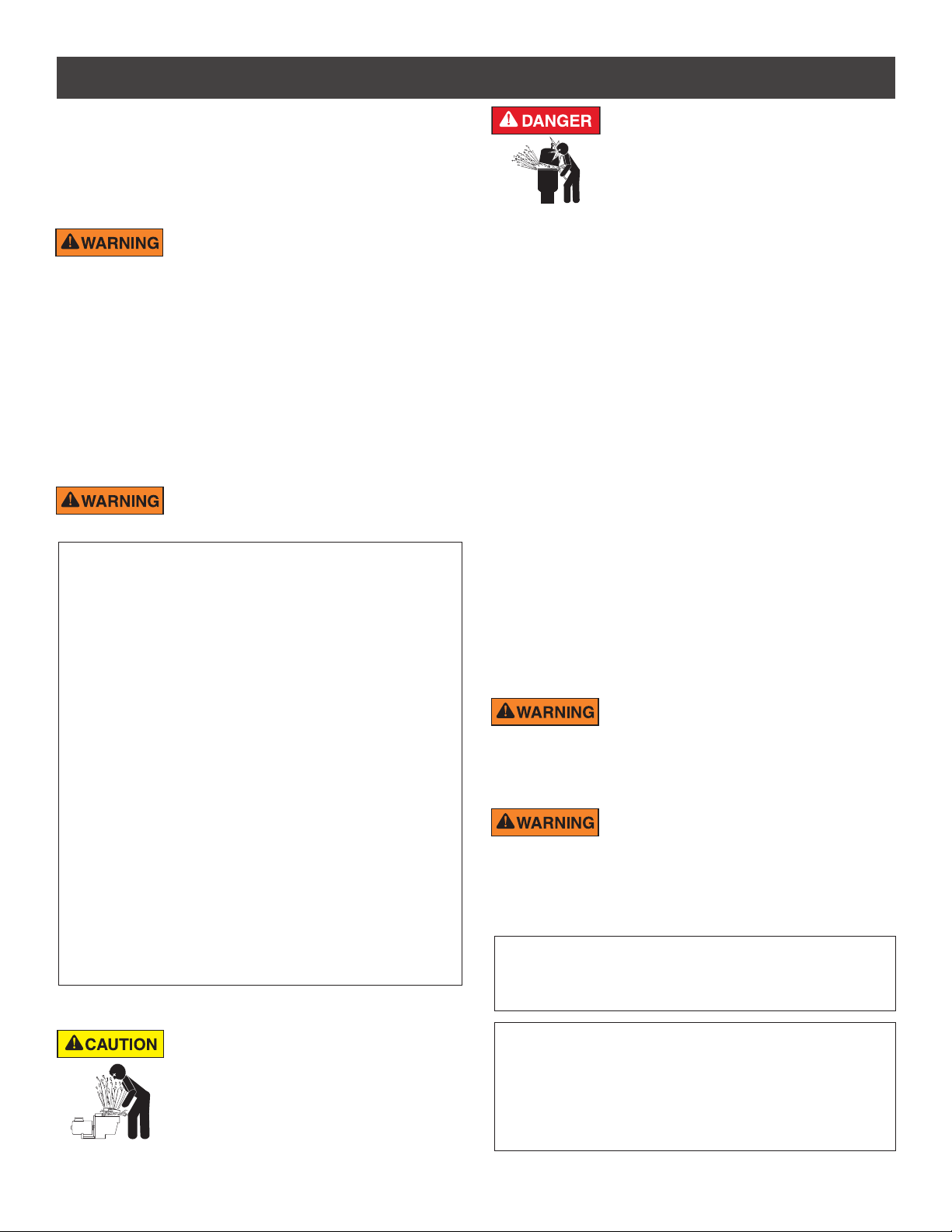
HAZARDOUS PRESSURE: STAND CLEAR OF
PUMP AND FILTER DURING START UP
Circulation systems operate under high pressure.
When any part of the circulating system (i.e.
locking ring, pump, filter, valves, etc.) is serviced,
air can enter the system and become pressurized.
Pressurized air can cause the pump housing cover, filter lid, and valves
to violently separate which can result in severe personal injury or death.
Filter tank lid and strainer cover must be properly secured to prevent
violent separation. Stand clear of all circulation system equipment when
turning on or starting up pump.
Before servicing equipment, make note of the filter pressure. Be sure
that all controls are set to ensure the system cannot inadvertently start
during service. Turn off all power to the pump. IMPORTANT: Place filter
manual air relief valve in the open position and wait for all pressure
in the system to be relieved.
Before starting the system, fully open the manual air relief valve and place
all system valves in the “open” position to allow water to flow freely from the
tank and back to the tank. Stand clear of all equipment and start the pump.
IMPORTANT: Do not close filter manual air relief valve until all
pressure has been discharged from the valve and a steady stream
of water appears. Observe filter pressure gauge and be sure it is not
higher than the pre-service condition.
General Installation Information
• All work must be performed by a qualified service professional, and
must conform to all national, state, and local codes.
• Install to provide drainage of compartment for electrical components.
• These instructions contain information for a variety of pump models
and therefore some instructions may not apply to a specific model. All
models are intended for use in swimming pool applications. The pump
will function correctly only if it is properly sized to the specific application
and properly installed.
Pumps improperly sized or installed or used in
applications other than for which the pump was
intended can result in severe personal injury or death. These risks
may include but not be limited to electric shock, fire, flooding, suction
entrapment or severe injury or property damage caused by a structural
failure of the pump or other system component.
The pump can produce high levels of suction within
the suction side of the plumbing system. These
high levels of suction can pose a risk if a person comes within the close
proximity of the suction openings. A person can be seriously injured
by this high level of vacuum or may become trapped and drown. It is
absolutely critical that the suction plumbing be installed in accordance
with the latest national and local codes for swimming pools.
Pumps and replacement motors that are single speed and
one (1) Total HP or greater cannot be sold, offered for sale, or
installed in a residential pool for filtration use in California, Title
20 CCR sections 1601-1609.
Warnings and safety instructions for Pentair Aquatic Systems pumps
and other related products are available at:
http://www.pentairpool.com/pool-owner/safety-warnings/ or call
(800) 831-7133 for additional free copies of these instructions.
Please refer to http://www.pentairpool.com/pool-owner/safety-
warnings/ for warning and safety instructions related to the this
product.
Warning Page P/N 352557 Rev. C 7/18
1
INSTALLATION
Only a qualified plumbing professional should install the WhisperFlo® High Performance Pump. Refer to “Pump
Warning And Safety Instructions” on pages ii - iii for additional installation and safety information.
Location
Be sure the pump location meets the following
requirements:
Note: Do not install this pump within an outer enclosure
or beneath the skirt of a hot tub or spa unless marked
accordingly.
1. Install the pump as close to the pool or spa as possible.
To reduce friction loss and improve efficiency, use
short, direct suction piping returns.
2. Install a minimum of 5 feet (1.52 meters) from the
inside wall of the pool and spa. Canadian installations
require a minimum of 9.8 feet (3 meters) from pool
water level.
3. Install the pump a minimum of 3 feet (.9 meters)
from the heater outlet.
4. Do not install the pump more than 10 feet (3 meters)
above the water level.
5. Install the pump in a well ventilated location protected
from excessive moisture (i.e., rain gutter downspouts,
sprinklers, etc.)
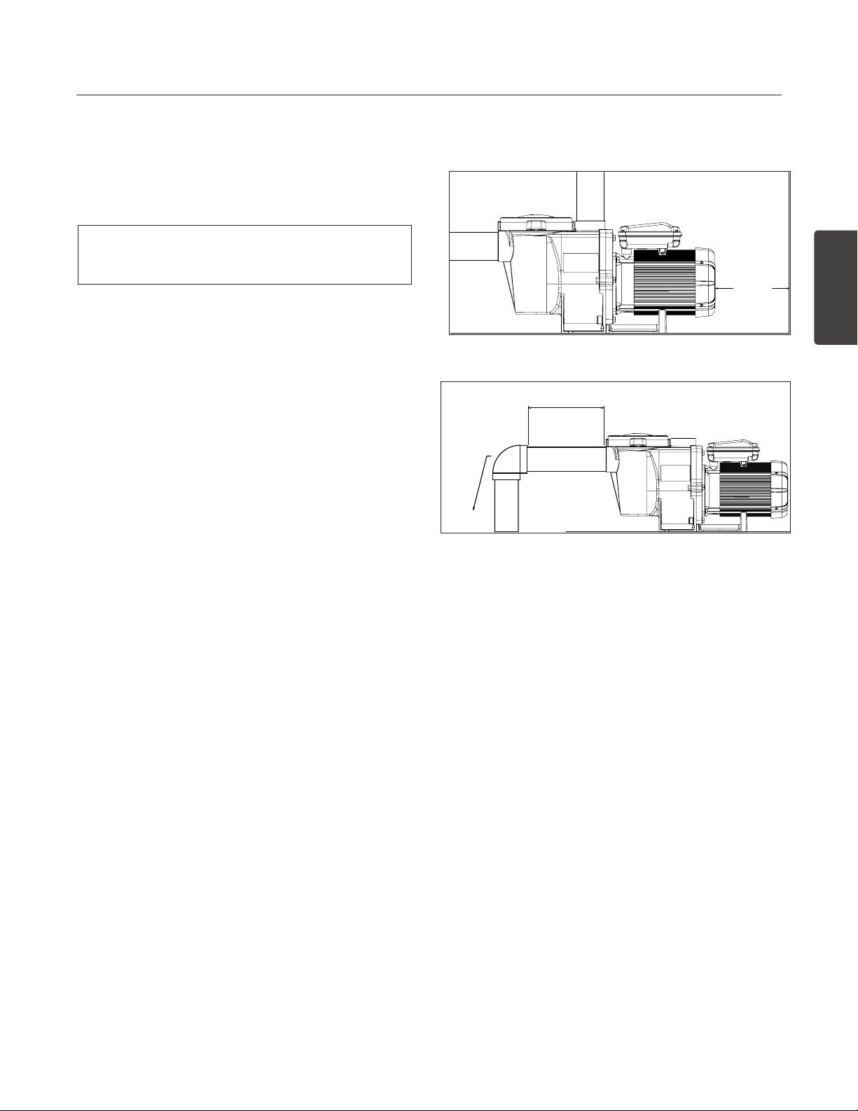
6. Install the pump with a rear clearance of at least 3
inches (76.2 mm) so that the motor can be removed
easily for maintenance and repair.
Piping
1. For improved pool plumbing, it is recommended to
use a larger pipe size. When installing the inlet and
outlet fittings (male adaptors), use thread sealant.
2. Piping on the suction side of the pump should be the
same or larger than the return line diameter.
3. Plumbing on the suction side of the pump should be
as short as possible.
4. For most installations Pentair recommends installing
a valve on both the pump suction and return lines
so that the pump can be isolated during routine
maintenance. However, we also recommend that a
valve, elbow or tee installed in the suction line should
be no closer to the front of the pump than five (5)
times the suction line diameter.
Example: A 2 inch pipe requires a 10 inch (25.4
cm) straight run in front of the suction inlet of the
pump. This will help the pump prime faster and last
longer.
Note: DO NOT install 90° elbows directly into the
pump inlet or outlet.
ENGLISH
3 IN.
(76.2CM)
MINIMUM
Pump Rear Clearance
5 x SUCTION PIPE DIAMETER
ELBOW
Recommended Piping
Fittings and Valves
1. Do not install 90° elbows directly into pump inlet.
2. Flooded suction systems should have gate valves
installed on suction and discharge pipes for
maintenance, however, the suction gate valve should
be no closer than five times the suction pipe diameter
as described in this section.
3. Use a check valve in the discharge line when using
this pump for any application where there is significant
height to the plumbing after the pump.
4. Be sure to install check valves when plumbing in
parallel with another pump. This helps prevent reverse
rotation of the impeller and motor.
WHISPERFLO
®
High Performance Pump Installation and User’s GuideWHISPERFLO

2
le
Bonding Lug
Bonding
Lug
Ground
Screw
1/2” NPT
Receptacle for
Liquid Tight
Connector
Motor Shaft
Flats for 1/2”
Wrench
Ground
or
Electrical Installation
RISK OF ELECTRICAL SHOCK OR ELECTROCUTION. This pump must be installed by a licensed or certified electrician or
a qualified service professional in accordance with the National Electrical Code (NEC) and all other applicable national or local
codes and ordinances. Improper installation will create an electrical hazard which could result in death or serious injury to users,
installers, or others due to electrical shock, and may also cause damage to property.
Always disconnect power to the pump at the circuit breaker before servicing the pump. Failure to do so could result in
death or serious injury to service people, users or others due to electric shock.
Read all servicing instructions before working on the pump.
Wiring
1. Be sure all electrical breakers, switches and automatic
controls are turned off before wiring motor.
STORED CHARGE - Wait at least sixty
(60) seconds before servicing.
2. Become familiar with the wiring diagram, volts, hertz,
amps and phase of your particular pump motor. All of
this information is provided on the motor nameplate
label found on the side of the motor.
3. Be sure that the supply voltage meets the requirements
listed on the motor nameplate. If these requirements
are not met, permanent motor damage may occur.
4. For wiring sizes and general guidelines for proper
electrical installation, please follow the specifications
defined in the National Electrical Code and all other
applicable national or local codes.
5. 3-Phase motors require external overload protection.
An initial inspection is needed to ensure proper
rotation of the pump.
Once installed, momentarily cycle the power on and
then off. Note the rotation of the motor fan or shaft as
it comes to a stop. If wired correctly the motor shaft
and/or fan will match the rotation arrow noted on the
pump.
6. Use a strain relief and be sure all electrical connections
are clean and tight.
7. Cut the wires to the appropriate length so they do
not overlap or touch when connected.
Bonding
1. Bond the motor to the structure in accordance with
the National Electrical Code and all other applicable
national or local codes. Use a solid copper bonding
conductor not smaller than 8 AWG. For Canadian
installations, a 6 AWG or larger solid copper bonding
conductor is required. Run a wire from the external
bonding screw or lug to the bonding structure.
2. Connect the wire from the accessible bonding lug
on the motor to all metal parts of the swimming
pool, spa, or hot tub structure and to all electrical
equipment, metal conduit, and metal piping within 5
feet (1.52 meters) of the inside walls of the swimming
pool, spa, or hot tub. Run a wire from the external
bonding screw or lug to the bonding structure.
Before establishing or restoring power to
the pump, be sure all electrical connections
are tight and all electrical and wiring compartment covers are
properly installed.
Note: When the pump is started and stopped by removing
power with a relay or timer, a two-pole device should
be used to apply and remove power to both POWER
LINE TERMINALS.
Pentair offers GFCI breakers which offer appropriate
personal protection while meeting 2008 to current
NEC Standards for Pool Pumps. See Pentair product
catalog for details.
Grounding
1. Permanently ground the motor using the green ground
screw, as shown below. Use the correct wire size and
type specified by National Electrical Code. Be sure
the ground wire is connected to an electrical service
ground.
2. The pump should be permanently connected to either
a circuit breaker, 2-pole timer or 2-pole relay.
Note: If AC power is supplied by a GFCI circuit breaker,
the pump should be wired on its own independent
circuit unless the pump is operated in tandem
with a Pentair salt chlorine generator.
Section P/N 350486 Rev. C 8/24/17
WHISPERFLO
®
High Performance Pump Installation and User’s Guide
Motor Shaft
Flats for 1/2”
Wrench
Ground
Screw
1/2” NPT Receptac
for Liquid Tight
Connector
Screw
1/2” NPT
Receptacle f
Liquid Tight
Connector
Bonding
Lug
Motor Shaft
Flats for 1/4”
Allen Wrench
3
MAINTENANCE
DO NOT open the strainer pot if pump fails to prime or if pump has been operating without water in the strainer pot. Pumps operated
in these circumstances may experience a build up of vapor pressure and may contain scalding hot water. Opening the pump may
cause serious personal injury. In order to avoid the possibility of personal injury, make sure the suction and discharge valves are open and strainer pot
temperature is cool to touch, then open with extreme caution.
To prevent damage to the pump and for proper operation of the system, clean pump strainer and skimmer baskets regularly.
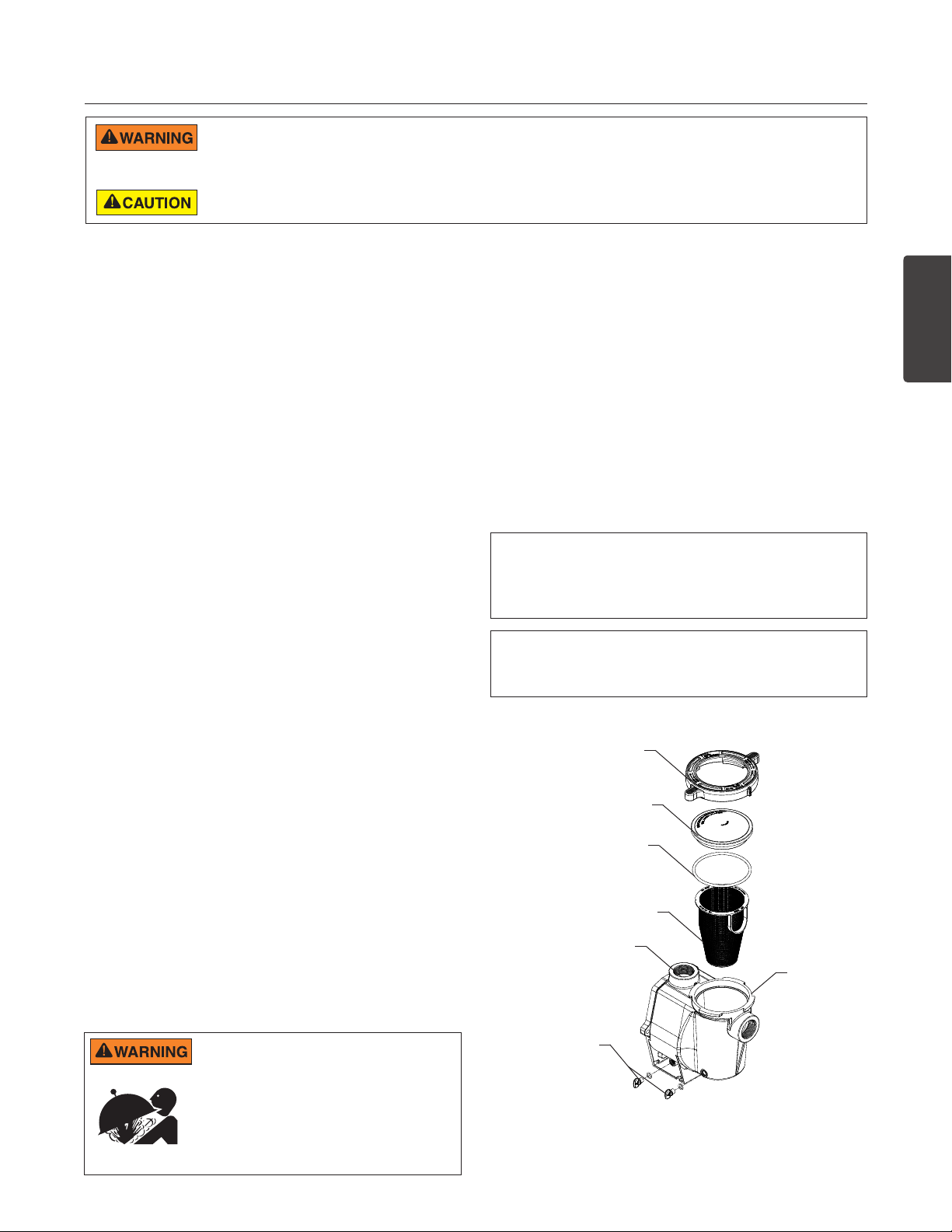
Pump Strainer Basket
The pump strainer basket (or ‘strainer pot’, ‘hair and lint
pot’), is located in front of the volute. Inside the chamber
is the basket which must be kept clean of leaves and
debris at all times. View basket through the ‘See Through
Lid’ to inspect for leaves and debris.
Regardless of the length of time between filter cleaning,
it is most important to visually inspect the basket at least
once a week. A dirty basket will reduce the efficiency of
the filter and heater and also put an abnormal stress on
the pump motor which would result in a costly repair bill.
Cleaning the Pump Strainer Basket
1. Turn off the pump at the circuit breaker.
2. Relieve pressure in the system by allowing the water
to cool.
3. Gently tap the clamp in a counter-clockwise direction
to remove the clamp and lid.
4. Remove debris and rinse out the basket. Replace
the basket if it is cracked.
5. Put the basket back into the housing. Be sure to align
the notch in the bottom of the basket with the rib in
the bottom of the volute.
6. Fill the pump pot and volute up to the inlet port with
water.
7. Clean the cover, O-ring, and sealing surface of the
pump pot. Note: It is important to keep the lid O-ring
clean and well lubricated.
8. Reinstall the lid by placing the lid on the pot. Be sure
the lid O-ring is properly placed. Seat the clamp and
lid on the pump then turn clockwise until the handles
are horizontal.
9. Turn the power “ON” at the house circuit breaker.
Reset the pool time clock to the correct time.
10. Open the High Flow manual air relief valve on top of
the filter.
11. Stand clear of the filter. Start the pump.
12. Bleed air from the filter until a steady stream of water
comes out. Close the High Flow™ Manual Air Relief
Valve.
THIS SYSTEM OPERATES UNDER HIGH
PRESSURE. When any part of the circulating
system (e.g., Lock Ring, Pump, Filter, Valves, etc.)
is serviced, air can enter the system and become
pressurized. Pressurized air can cause the lid to
separate which can result in serious injury, death,
or property damage. To avoid this potential hazard,
follow above instructions.
WHISPERFLO
Winterizing
You are responsible for determining when freezing
conditions may occur. If freezing conditions are
expected, take the following steps to reduce the risk
of freeze damage. Freeze damage is not covered
under warranty.
To prevent freeze damage, follow the procedures below:
1. Shut off electrical power for the pump at the circuit
breaker.
2. Drain the water out of the pump housing by removing
the two thumb-twist drain plugs from the housing.
Store the plugs in the pump basket.
3. Cover the motor to protect it from severe rain, snow
and ice.
Note: Do not wrap motor with plastic or other air tight
materials during winter storage. The motor may be
covered during a storm, winter storage, etc., but never
when operating or expecting operation.
In mild climate areas, when temporary freezing
conditions may occur, run your filtering equipment
all night to prevent freezing.
Clamp, pot
Lid
O-Ring
Strainer
Basket
Volute
Pot
Drain
Plugs
Strainer Pot Assembly
®
High Performance Pump Installation and User’s GuideWHISPERFLO
ENGLISH

4
SERVICING
Always disconnect power to the pump at the circuit breaker and disconnect the communication cable before servicing the pump.
Failure to do so could result in death or serious injury to service people, users or others due to electric shock. Read all servicing
instructions before working on the pump.
DO NOT open the strainer pot if pump fails to prime or if pump has been operating without water in the strainer pot. Pumps operated
in these circumstances may experience a build up of vapor pressure and may contain scalding hot water. Opening the pump may
cause serious personal injury. In order to avoid the possibility of personal injury, make sure the suction and discharge valves are open and strainer pot
temperature is cool to touch, then open with extreme caution.
Be sure not to scratch or mar the polished shaft seal faces; seal will leak if faces are damaged. The polished and lapped faces of
the seal could be damaged if not handled with care.
Motor Care
Protect from heat
1. Shade the motor from the sun.
2. Any enclosure must be well ventilated to prevent
overheating.
3. Provide ample cross ventilation.
Protect against dirt
1. Protect from any foreign matter.
2. Do not store (or spill) chemicals on or near the motor.
3. Avoid sweeping or stirring up dust near the motor
while it is operating.
4. If a motor has been damaged by dirt it voids the
motor warranty.
5. Clean the lid and clamp, O-ring, and sealing surface
of the pump pot.
Protect against moisture
1. Protect from splashing or sprayed water.
2. Protect from extreme weather.
3. If a motor has become wet - let it dry before operating.
Do not allow the pump to operate if it has been flooded.
4. If a motor has been damaged by water it voids the
motor warranty.
Note: When replacing the motor, be certain that the
motor support is correctly positioned to support the
size of motor being installed.
Shaft Seal Replacement
The Shaft Seal consists primarily of two parts, a rotating
member and a ceramic seal.
The pump requires little or no service other than
reasonable care, however, a Shaft Seal may occasionally
become damaged and must be replaced.
Pump Disassembly
All moving parts are located in the rear sub-assembly
of this pump.
Tools required:
• 3/32 inch Allen head wrench
• 1/2 inch open end wrench
• 9/16 inch open end wrench
• Flat blade screwdriver
• #2 Phillips screwdriver
To remove and repair the motor subassembly, follow the
steps below:
1. Turn off the pump circuit breaker at the main panel.
2. Drain the pump by removing the drain plugs.
3. Remove the 6 bolts that hold the main pump body
(strainer pot/volute) to the rear sub-assembly.
4. GENTLY pull the two pump halves apart, removing
the rear sub-assembly.
5. Use a 3/32 inch Allen head wrench to loosen the
two holding screws located on the diffuser.
6. Hold the impeller securely in place and remove
the impeller lock screw by using a #2 Phillips
screwdriver. The screw is a left-handed thread and
loosens in a clockwise direction.
7. Remove the shaft cap located at the back of the
motor and hold the shaft secure with a ½ inch
open-end wrench.
8. To unscrew the impeller from the shaft, twist the
impeller counterclockwise.
9. Remove the four bolts from the seal plate to the
motor, using a 9/16 inch wrench.
Note: The polished and lapped faces of the seal could
be damaged if not handled with care.
WHISPERFLO
®
High Performance Pump Installation and User’s Guide
5
LOCKSCREW
DO NOT run the pump dry. If the pump is run dry, the mechanical seal will be damaged and the pump will start leaking. If this
occurs, the damaged seal must be replaced. ALWAYS maintain proper water level. If the water level falls below the suction port,
the pump will draw air through the suction port, losing the prime and causing the pump to run dry, resulting in a damaged seal.
Continued operation in this manner could cause a loss of pressure, resulting in damage to the pump case, impeller and seal and may cause property
damage and personal injury.
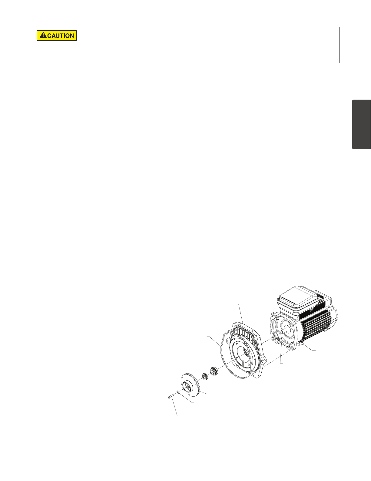
Pump Reassembly
1. When installing the replacement shaft seal, use
silicone sealant on the metal portion before
pressing into the seal plate, being careful to keep
off of the seal face. Ensure the seal is fully seated
and allow 24 hours for sealant to cure. (Complete
seal plate w/seal replacement kit available, P/N
350201/350101.)
2. Before installing the ceramic section of the seal into
the impeller, be sure the impeller is clean. Use a
light density soap and water to seal the seal. Press
the seal into the impeller with your thumbs and wipe
off the ceramic and carbon faces with a clean cloth.
3. Remount the seal plate to the motor by installing
bolts in an X pattern and tightening to 70 in-lbs.
4. Clean the motor shaft thread and the impeller
insert, then screw the impeller onto the motor shaft.
5. Screw in the impeller lock screw (counter-clockwise
and tighten to 25 in-lbs. while holding the motor
shaft with wrench).
6. Remount the diffuser onto the seal plate. Make
sure the plastic pins and holding screw inserts are
aligned.
7. Grease the diffuser O-ring and seal plate gasket.
8. Grease the bolt threads, assemble the motor subassembly to the strainer pot-pump body by using
the two through bolts for proper alignment. Do not
tighten the through bolts until all 6 bolts are in place
and finger tightened. Torque in a cross pattern to
110 in-lbs.
9. Fill the pump with water.
10. Reinstall the pump lid and plastic clamp;
see the next section, ‘Restart Instructions’.
11. Reprime the system.
Restart Instructions
If pump is installed below the water level of the pool,
close return and suction lines prior to opening hair and
lint pot on pump. Make sure to re-open valves prior to
operating.
Priming the Pump
The pump strainer pot must be filled with water before
the pump is initially started. Follow these steps to
prime the pump:
1. Remove the pump lid plastic clamp. Remove the
pump lid.
2. Fill the pump strainer pot with water.
3. Reassemble the pump cover and plastic clamp
onto the strainer pot. The pump is now ready to
prime.
4. Open the air release valve on the filter, and stand
clear of the filter.
5. Turn on the switch or time clock.
6. When water comes out of the air release valve,
close the valve. The system should now be free of
air and recirculating water to and from the pool.
7. For 2-speed pumps:
• Pump should run on high-speed for priming.
• The pump should not run longer than 8
minutes before priming is achieved.
SEAL PLATE
GASKET
ENGLISH
LOCKSREW SEAL
WHISPERFLO
IMPELLER
®
High Performance Pump Installation and User’s GuideWHISPERFLO
BOLT
MOTOR SHAFT
Motor Assembly
 Loading...