

Page 1
®
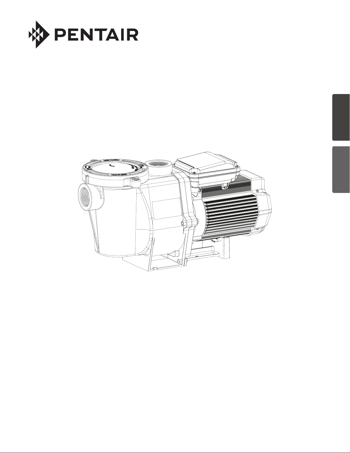
WHISPERFLO
HIGH PERFORMANCE PUMP
ENGLISH 1 ESPAÑOL 10
INSTALLATION AND
USER’S GUIDE
IMPORTANT SAFETY INSTRUCTIONS
READ AND FOLLOW ALL INSTRUCTIONS
SAVE THESE INSTRUCTIONS
WHISPERFLO
®
High Performance Pump Installation and User’s Guide
Page 2

i
CUSTOMER SERVICE / TECHNICAL SUPPORT
If you have questions about ordering Pentair Aquatic Systems replacement parts, and pool products, please contact:
Customer Service and Technical Support, USA
(8 A.M. to 4:30 P.M. — Eastern/Pacific Times)
Phone: (800) 831-7133
Fax: (800) 284-4151
Web site
Visit www.pentairpool.com or www.staritepool.com
TABLE OF CONTENTS
Important Pump Warning and
Safety Instructions ................................................
Installation ..............................................................
Location
Piping
Fittings and Valves
Electrical Wiring Installation
Wiring
Grounding
Bonding
Maintenance ...........................................................
Pump Strainer Basket
Cleaning the Pump Strainer Basket
Winterizing
Sanford, North Carolina (8 A.M. to 4:30 P.M. ET)
Phone: (919) 566-8000
Fax: (919) 566-8920
Moorpark, California (8 A.M. to 4:30 P.M. PT)
Phone: (805) 553-5000 (Ext. 5591)
Fax: (805) 553-5515
Servicing .................................................................
ii
1
1
1
1
2
2
2
2
3
3
3
Motor Care
Shaft Seal Replacement
Pump Disassembly
Pump Reassembly
Restart Instructions
Priming the Pump
Troubleshooting .....................................................
Replacement Parts .................................................
Illustrated Parts List
Pump Performance Curves
Español Tabla de Contenidos ................................
3
4
4
4
4
5
5
5
6
7
7
9
11
© 2018 Pentair Water Pool and Spa, Inc. All rights reserved. This document is subject to change without notice.
1620 Hawkins Ave., Sanford, NC 27330 • (919) 566-8000
10951 West Los Angeles Ave., Moorpark, CA 93021 • (805) 553-5000
All Pentair trademarks and logos are owned by Pentair or one of its global affiliates. WhisperFlo® and High Flow™ are trademarks
and/or registered trademarks of Pentair Water Pool and Spa, Inc. and/or its affiliated companies in the United States and/ or other
countries. Unless expressly noted, names and brands of third parties that may be used in this document are not used to indicate an
affiliation or endorsement between the owners of these names and brands and Pentair Water Pool and Spa, Inc. Those names and
brands may be the trademarks or registered trademarks of those third parties. Because we are continuously improving our products
and services, Pentair reserves the right to change specifications without prior notice. Pentair is an equal opportunity employer.
P/N 071109 Rev. L 6/28/18
WHISPERFLO
®
High Performance Pump Installation and User’s Guide
Page 3
IMPORTANT PUMP WARNING AND SAFETY INSTRUCTIONS
F
IMPORTANT NOTICE
This guide provides installation and operation instructions for this pump.
Consult Pentair with any questions regarding this equipment.
Attention Installer: This guide contains important information about the
installation, operation and safe use of this product. This information should
be given to the owner and/or operator of this equipment after installation
or left on or near the pump.
Attention User: This manual contains important information that will help
you in operating and maintaining this product. Please retain it for future
reference.
READ AND FOLLOW ALL INSTRUCTIONS
SAVE THESE INSTRUCTIONS
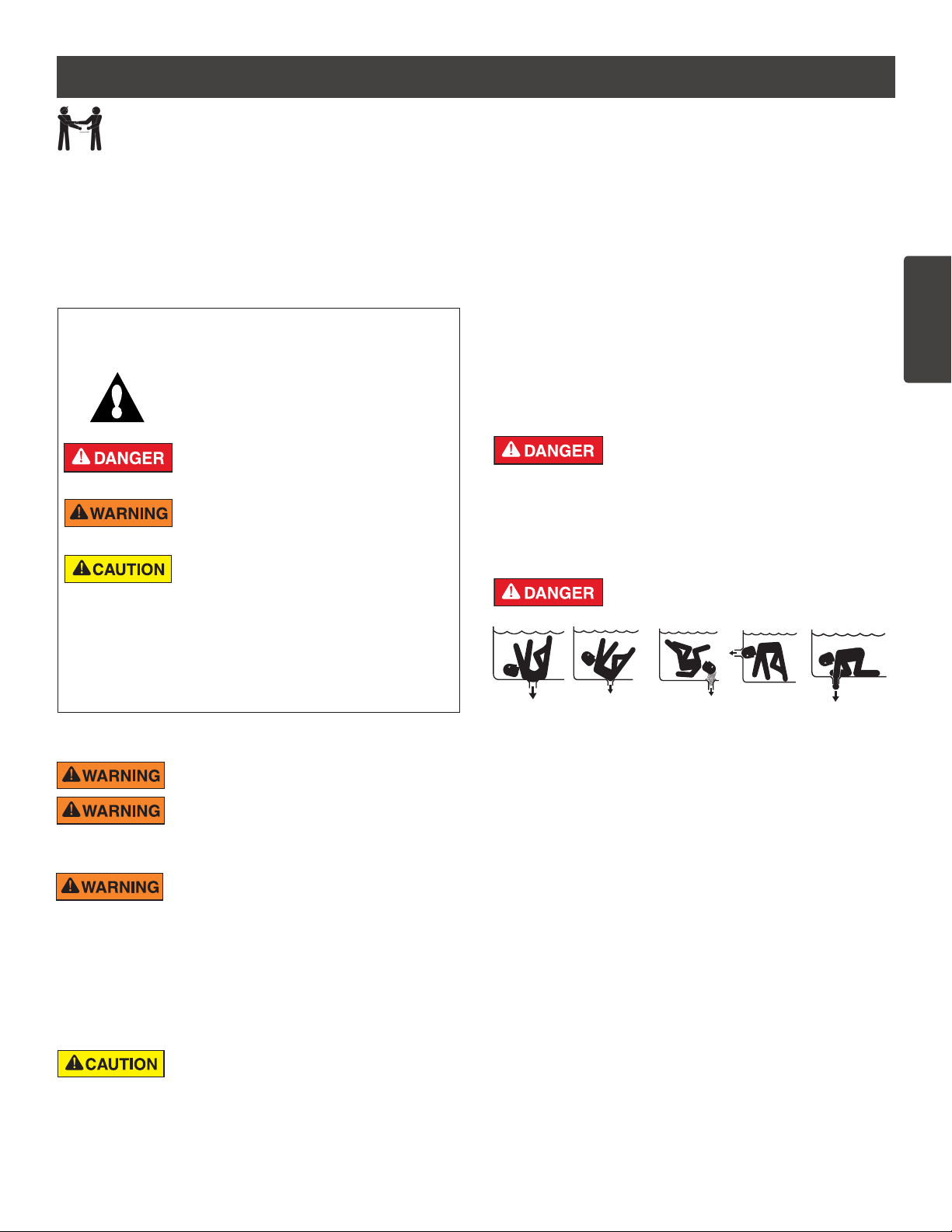
This is the safety alert symbol. When you see this
symbol on your system or in this manual, look for
one of the following signal words and be alert to
the potential for personal injury.
Warns about hazards that can cause death,
serious personal injury, or major property damage
if ignored.
Warns about hazards that may cause death,
serious personal injury, or major property damage
if ignored.
Warns about hazards that may or can cause minor
personal injury or property damage
if ignored.
NOTE Indicates special instructions not related to
hazards.
Carefully read and follow all safety instructions in this manual and on
equipment. Keep safety labels in good condition; replace if missing
or damaged.
When installing and using this electrical equipment, basic safety
precautions should always be followed, include the following:
Do not permit children to use this product.
RISK OF ELECTRICAL SHOCK. Connect only to
a branch circuit protected by a ground-fault circuitinterrupter (GFCI). Contact a qualified electrician if you cannot verify that
the circuit is protected by a GFCI.
This unit must be connected only to a supply circuit
that is protected by a ground-fault circuit-interrupter
(GFCI). Such a GFCI should be provided by the installer and should
be tested on a routine basis. To test the GFCI, push the test button.
The GFCI should interrupt power. Push the reset button. Power should
be restored. If the GFCI fails to operate in this manner, the GFCI is
defective. If the GFCI interrupts power to the pump without the test button
being pushed, a ground current is flowing, indicating the possibility of an
electric shock. Do not use this pump. Disconnect the pump and have the
problem corrected by a qualified service representative before using.
This pump is for use with permanent swimming
pools and may also be used with hot tubs and spas
if so marked. Do not use with storable pools. A permanently-installed pool
is constructed in or on the ground or in a building such that it cannot be
readily disassembled for storage. A storable pool is constructed so that
it is capable of being readily disassembled for storage and reassembled
to its original integrity.
General Warnings
• Never open the inside of the drive motor enclosure. There is a
capacitor bank that holds a 230 VAC charge even when there is no
power to the unit.
• The pump is not submersible.
• The pump is capable of high flow rates; use caution when installing
and programming to limit pumps performance potential with old or
questionable equipment.
• Code requirements for electrical connection differ from country to
country, state to state, as well as local municipalities. Install equipment
in accordance with the National Electrical Code and all applicable
local codes and ordinances.
• Before servicing the pump; switch OFF power to the pump by
disconnecting the main circuit to the pump.
• This appliance is not intended for use by persons (including children) of
reduced physical, sensory or mental capabilities, or lack of experience
and knowledge, unless they have been given supervision or instruction
concerning the use of the appliance by a person responsible for their
safety.
FAILURE TO FOLLOW ALL INSTRUCTIONS AND
WARNINGS CAN RESULT IN SERIOUS BODILY
INJURY OR DEATH. THIS PUMP SHOULD BE INSTALLED AND
SERVICED ONLY BY A QUALIFIED POOL SERVICE PROFESSIONAL.
INSTALLERS, POOL OPERATORS AND OWNERS MUST READ
THESE WARNINGS AND ALL INSTRUCTIONS IN THE OWNER’S
MANUAL BEFORE USING THIS PUMP. THESE WARNINGS AND
THE OWNER’S MANUAL MUST BE LEFT WITH THE POOL OWNER.
SUCTION ENTRAPMENT HAZARD: STAY OFF
THE MAIN DRAIN AND AWAY FROM ALL SUCTION
OUTLETS!
THIS PUMP PRODUCES HIGH LEVELS OF SUCTION AND CREATES
A STRONG VACUUM AT THE MAIN DRAIN AT THE BOTTOM OF THE
BODY OF WATER. THIS SUCTION IS SO STRONG THAT IT CAN TRAP
ADULTS OR CHILDREN UNDER WATER IF THEY COME IN CLOSE
PROXIMITY TO A DRAIN OR A LOOSE OR BROKEN DRAIN COVER
OR GRATE.
THE USE OF UNAPPROVED COVERS OR ALLOWING USE OF
THE POOL OR SPA WHEN COVERS ARE MISSING, CRACKED OR
BROKEN CAN RESULT IN BODY OR LIMB ENTRAPMENT, HAIR
ENTANGLEMENT, BODY ENTRAPMENT, EVISCERATION AND/OR
DEATH.
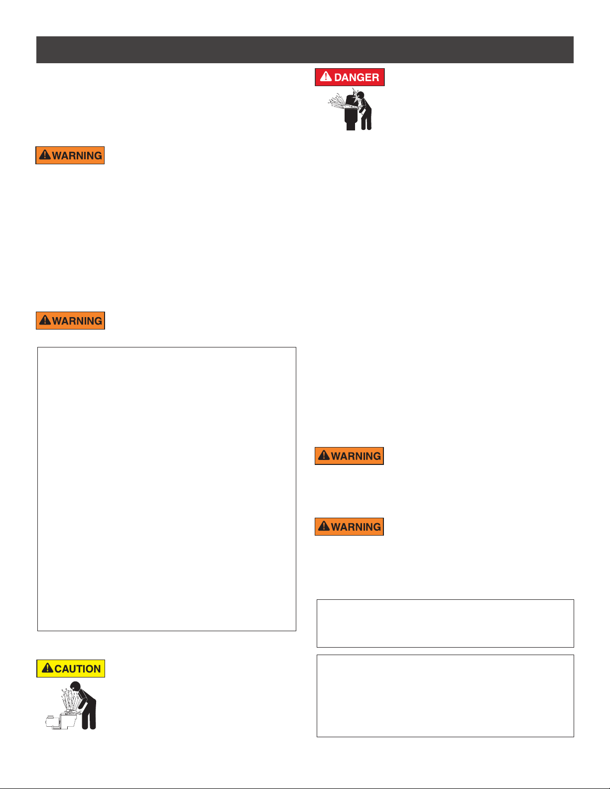
The suction at a drain or outlet can cause:
Limb Entrapment: When a limb is sucked or inserted into an opening
resulting in a mechanical bind or swelling. This hazard is present when
a drain cover is missing, broken, loose, cracked or not properly secured.
Hair Entanglement: When the hair tangles or knots in the drain cover,
trapping the swimmer underwater. This hazard is present when the flow
rating of the cover is too small for the pump or pumps.
Body Entrapment: When a portion of the body is held against the drain
cover trapping the swimmer underwater. This hazard is present when the
drain cover is missing, broken or the cover flow rating is not high enough
for the pump or pumps.
Evisceration/Disembowelment: When a person sits on an open pool
(particularly a child wading pool) or spa outlet and suction is applied directly
to the intestines, causing severe intestinal damage. This hazard is present
when the drain cover is missing, loose, cracked, or not properly secured.
WHISPERFLO
®
High Performance Pump Installation and User’s Guide
ii
ENGLISH
Page 4
iii
IMPORTANT PUMP WARNING AND SAFETY INSTRUCTIONS
Mechanical Entrapment: When jewelry, swimsuit, hair decorations, finger,
toe or knuckle is caught in an opening of an outlet or drain cover. This
hazard is present when the drain cover is missing, broken, loose, cracked,
or not properly secured.
NOTE: ALL SUCTION PLUMBING MUST BE INSTALLED IN
ACCORDANCE WITH THE LATEST NATIONAL AND LOCAL CODES,
STANDARDS AND GUIDELINES.
TO MINIMIZE THE RISK OF INJURY DUE TO
SUCTION ENTRAPMENT HAZARD:
• A properly installed and secured ANSI/ASME A112.19.8 approved
anti-entrapment suction cover must be used for each drain.
• Each suction cover must be installed at least three (3’) feet apart, as
measured from the nearest point to nearest point.
• Regularly inspect all covers for cracks, damage and advanced
weathering.
• If a cover becomes loose, cracked, damaged, broken or is missing,
replace with an appropriate certified cover.
• Replace drain covers as necessary. Drain covers deteriorate over
time due to exposure to sunlight and weather.
• Avoid getting hair, limbs or body in close proximity to any suction
cover, pool drain or outlet.
• Disable suction outlets or reconfigure into return inlets.
A clearly labeled emergency shut-off switch for the
pump must be in an easily accessible, obvious place.
Make sure users know where it is and how to use it in case of emergency.
The Virginia Graeme Baker (VGB) Pool and Spa Safety Act creates
new requirements for owners and operators of commercial swimming
pools and spas.
Commercial pools or spas constructed on or after December 19, 2008,
shall utilize:
(A) A multiple main drain system without isolation capability with suction
outlet covers that meet ASME/ANSI A112.19.8a Suction Fittings for
Use in Swimming Pools, Wading Pools, Spas, and Hot Tubs and either:
(i) A safety vacuum release system (SVRS) meeting ASME/ANSI
A112.19.17 Manufactured Safety Vacuum Release systems (SVRS)
for Residential and Commercial Swimming Pool, Spa, Hot Tub,
and Wading Pool Suction Systems and/or ASTM F2387 Standard
Specification for Manufactured Safety Vacuum Release Systems
(SVRS) for Swimming pools, Spas and Hot Tubs or
(ii) A properly designed and tested suction-limiting vent system or
(iii) An automatic pump shut-off system.
Commercial pools and spas constructed prior to December 19, 2008,
with a single submerged suction outlet shall use a suction outlet cover
that meets ASME/ANSI A112.19.8a and either:
(A) A SVRS meeting ASME/ANSI A112.19.17 and/or ASTM F2387, or
(B) A properly designed and tested suction-limiting vent system, or
(C) An automatic pump shut-off system, or
(D) Disabled submerged outlets, or
(E) Suction outlets shall be reconfigured into return inlets.
For Installation of Electrical Controls at Equipment Pad (ON/OFF
Switches, Timers and Automation Load Center)
Install all electrical controls at equipment pad, such as
on/off switches, timers, and control systems, etc. to
allow the operation (startup, shut-down, or servicing)
of any pump or filter so the user does not place any
portion of his/her body over or near the pump strainer
lid, filter lid or valve closures. This installation should
allow the user enough space to stand clear of the filter
and pump during system start-up, shut down or servicing of the system filter.
WHISPERFLO
®
High Performance Pump Installation and User’s Guide
HAZARDOUS PRESSURE: STAND CLEAR OF
PUMP AND FILTER DURING START UP
Circulation systems operate under high pressure.
When any part of the circulating system (i.e.
locking ring, pump, filter, valves, etc.) is serviced,
air can enter the system and become pressurized.
Pressurized air can cause the pump housing cover, filter lid, and valves
to violently separate which can result in severe personal injury or death.
Filter tank lid and strainer cover must be properly secured to prevent
violent separation. Stand clear of all circulation system equipment when
turning on or starting up pump.
Before servicing equipment, make note of the filter pressure. Be sure
that all controls are set to ensure the system cannot inadvertently start
during service. Turn off all power to the pump. IMPORTANT: Place filter
manual air relief valve in the open position and wait for all pressure
in the system to be relieved.
Before starting the system, fully open the manual air relief valve and place
all system valves in the “open” position to allow water to flow freely from the
tank and back to the tank. Stand clear of all equipment and start the pump.
IMPORTANT: Do not close filter manual air relief valve until all
pressure has been discharged from the valve and a steady stream
of water appears. Observe filter pressure gauge and be sure it is not
higher than the pre-service condition.
General Installation Information
• All work must be performed by a qualified service professional, and
must conform to all national, state, and local codes.
• Install to provide drainage of compartment for electrical components.
• These instructions contain information for a variety of pump models
and therefore some instructions may not apply to a specific model. All
models are intended for use in swimming pool applications. The pump
will function correctly only if it is properly sized to the specific application
and properly installed.
Pumps improperly sized or installed or used in
applications other than for which the pump was
intended can result in severe personal injury or death. These risks
may include but not be limited to electric shock, fire, flooding, suction
entrapment or severe injury or property damage caused by a structural
failure of the pump or other system component.
The pump can produce high levels of suction within
the suction side of the plumbing system. These
high levels of suction can pose a risk if a person comes within the close
proximity of the suction openings. A person can be seriously injured
by this high level of vacuum or may become trapped and drown. It is
absolutely critical that the suction plumbing be installed in accordance
with the latest national and local codes for swimming pools.
Pumps and replacement motors that are single speed and
one (1) Total HP or greater cannot be sold, offered for sale, or
installed in a residential pool for filtration use in California, Title
20 CCR sections 1601-1609.
Warnings and safety instructions for Pentair Aquatic Systems pumps
and other related products are available at:
http://www.pentairpool.com/pool-owner/safety-warnings/ or call
(800) 831-7133 for additional free copies of these instructions.
Please refer to http://www.pentairpool.com/pool-owner/safety-
warnings/ for warning and safety instructions related to the this
product.
Warning Page P/N 352557 Rev. C 7/18
Page 5
1
INSTALLATION
Only a qualified plumbing professional should install the WhisperFlo® High Performance Pump. Refer to “Pump
Warning And Safety Instructions” on pages ii - iii for additional installation and safety information.
Location
Be sure the pump location meets the following
requirements:
Note: Do not install this pump within an outer enclosure
or beneath the skirt of a hot tub or spa unless marked
accordingly.
1. Install the pump as close to the pool or spa as possible.
To reduce friction loss and improve efficiency, use
short, direct suction piping returns.
2. Install a minimum of 5 feet (1.52 meters) from the
inside wall of the pool and spa. Canadian installations
require a minimum of 9.8 feet (3 meters) from pool
water level.
3. Install the pump a minimum of 3 feet (.9 meters)
from the heater outlet.
4. Do not install the pump more than 10 feet (3 meters)
above the water level.
5. Install the pump in a well ventilated location protected
from excessive moisture (i.e., rain gutter downspouts,
sprinklers, etc.)
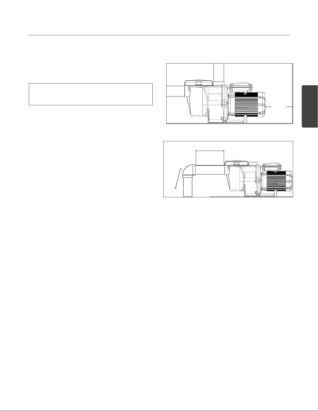
6. Install the pump with a rear clearance of at least 3
inches (76.2 mm) so that the motor can be removed
easily for maintenance and repair.
Piping
1. For improved pool plumbing, it is recommended to
use a larger pipe size. When installing the inlet and
outlet fittings (male adaptors), use thread sealant.
2. Piping on the suction side of the pump should be the
same or larger than the return line diameter.
3. Plumbing on the suction side of the pump should be
as short as possible.
4. For most installations Pentair recommends installing
a valve on both the pump suction and return lines
so that the pump can be isolated during routine
maintenance. However, we also recommend that a
valve, elbow or tee installed in the suction line should
be no closer to the front of the pump than five (5)
times the suction line diameter.
Example: A 2 inch pipe requires a 10 inch (25.4
cm) straight run in front of the suction inlet of the
pump. This will help the pump prime faster and last
longer.
Note: DO NOT install 90° elbows directly into the
pump inlet or outlet.
ENGLISH
3 IN.
(76.2CM)
MINIMUM
Pump Rear Clearance
5 x SUCTION PIPE DIAMETER
ELBOW
Recommended Piping
Fittings and Valves
1. Do not install 90° elbows directly into pump inlet.
2. Flooded suction systems should have gate valves
installed on suction and discharge pipes for
maintenance, however, the suction gate valve should
be no closer than five times the suction pipe diameter
as described in this section.
3. Use a check valve in the discharge line when using
this pump for any application where there is significant
height to the plumbing after the pump.
4. Be sure to install check valves when plumbing in
parallel with another pump. This helps prevent reverse
rotation of the impeller and motor.
WHISPERFLO
®
High Performance Pump Installation and User’s GuideWHISPERFLO
Page 6

2
le
Bonding Lug
Bonding
Lug
Ground
Screw
1/2” NPT
Receptacle for
Liquid Tight
Connector
Motor Shaft
Flats for 1/2”
Wrench
Ground
or
Electrical Installation
RISK OF ELECTRICAL SHOCK OR ELECTROCUTION. This pump must be installed by a licensed or certified electrician or
a qualified service professional in accordance with the National Electrical Code (NEC) and all other applicable national or local
codes and ordinances. Improper installation will create an electrical hazard which could result in death or serious injury to users,
installers, or others due to electrical shock, and may also cause damage to property.
Always disconnect power to the pump at the circuit breaker before servicing the pump. Failure to do so could result in
death or serious injury to service people, users or others due to electric shock.
Read all servicing instructions before working on the pump.
Wiring
1. Be sure all electrical breakers, switches and automatic
controls are turned off before wiring motor.
STORED CHARGE - Wait at least sixty
(60) seconds before servicing.
2. Become familiar with the wiring diagram, volts, hertz,
amps and phase of your particular pump motor. All of
this information is provided on the motor nameplate
label found on the side of the motor.
3. Be sure that the supply voltage meets the requirements
listed on the motor nameplate. If these requirements
are not met, permanent motor damage may occur.
4. For wiring sizes and general guidelines for proper
electrical installation, please follow the specifications
defined in the National Electrical Code and all other
applicable national or local codes.
5. 3-Phase motors require external overload protection.
An initial inspection is needed to ensure proper
rotation of the pump.
Once installed, momentarily cycle the power on and
then off. Note the rotation of the motor fan or shaft as
it comes to a stop. If wired correctly the motor shaft
and/or fan will match the rotation arrow noted on the
pump.
6. Use a strain relief and be sure all electrical connections
are clean and tight.
7. Cut the wires to the appropriate length so they do
not overlap or touch when connected.
Bonding
1. Bond the motor to the structure in accordance with
the National Electrical Code and all other applicable
national or local codes. Use a solid copper bonding
conductor not smaller than 8 AWG. For Canadian
installations, a 6 AWG or larger solid copper bonding
conductor is required. Run a wire from the external
bonding screw or lug to the bonding structure.
2. Connect the wire from the accessible bonding lug
on the motor to all metal parts of the swimming
pool, spa, or hot tub structure and to all electrical
equipment, metal conduit, and metal piping within 5
feet (1.52 meters) of the inside walls of the swimming
pool, spa, or hot tub. Run a wire from the external
bonding screw or lug to the bonding structure.
Before establishing or restoring power to
the pump, be sure all electrical connections
are tight and all electrical and wiring compartment covers are
properly installed.
Note: When the pump is started and stopped by removing
power with a relay or timer, a two-pole device should
be used to apply and remove power to both POWER
LINE TERMINALS.
Pentair offers GFCI breakers which offer appropriate
personal protection while meeting 2008 to current
NEC Standards for Pool Pumps. See Pentair product
catalog for details.
Grounding
1. Permanently ground the motor using the green ground
screw, as shown below. Use the correct wire size and
type specified by National Electrical Code. Be sure
the ground wire is connected to an electrical service
ground.
2. The pump should be permanently connected to either
a circuit breaker, 2-pole timer or 2-pole relay.
Note: If AC power is supplied by a GFCI circuit breaker,
the pump should be wired on its own independent
circuit unless the pump is operated in tandem
with a Pentair salt chlorine generator.
Section P/N 350486 Rev. C 8/24/17
WHISPERFLO
®
High Performance Pump Installation and User’s Guide
Motor Shaft
Flats for 1/2”
Wrench
Ground
Screw
1/2” NPT Receptac
for Liquid Tight
Connector
Screw
1/2” NPT
Receptacle f
Liquid Tight
Connector
Bonding
Lug
Motor Shaft
Flats for 1/4”
Allen Wrench
Page 7
3
MAINTENANCE
DO NOT open the strainer pot if pump fails to prime or if pump has been operating without water in the strainer pot. Pumps operated
in these circumstances may experience a build up of vapor pressure and may contain scalding hot water. Opening the pump may
cause serious personal injury. In order to avoid the possibility of personal injury, make sure the suction and discharge valves are open and strainer pot
temperature is cool to touch, then open with extreme caution.
To prevent damage to the pump and for proper operation of the system, clean pump strainer and skimmer baskets regularly.
Pump Strainer Basket
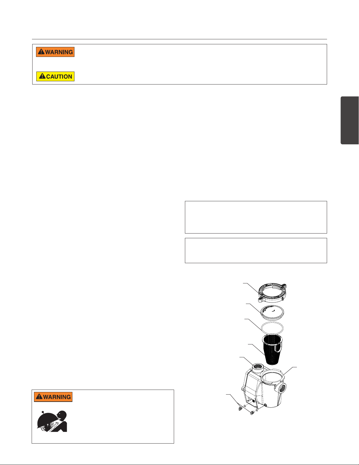
The pump strainer basket (or ‘strainer pot’, ‘hair and lint
pot’), is located in front of the volute. Inside the chamber
is the basket which must be kept clean of leaves and
debris at all times. View basket through the ‘See Through
Lid’ to inspect for leaves and debris.
Regardless of the length of time between filter cleaning,
it is most important to visually inspect the basket at least
once a week. A dirty basket will reduce the efficiency of
the filter and heater and also put an abnormal stress on
the pump motor which would result in a costly repair bill.
Cleaning the Pump Strainer Basket
1. Turn off the pump at the circuit breaker.
2. Relieve pressure in the system by allowing the water
to cool.
3. Gently tap the clamp in a counter-clockwise direction
to remove the clamp and lid.
4. Remove debris and rinse out the basket. Replace
the basket if it is cracked.
5. Put the basket back into the housing. Be sure to align
the notch in the bottom of the basket with the rib in
the bottom of the volute.
6. Fill the pump pot and volute up to the inlet port with
water.
7. Clean the cover, O-ring, and sealing surface of the
pump pot. Note: It is important to keep the lid O-ring
clean and well lubricated.
8. Reinstall the lid by placing the lid on the pot. Be sure
the lid O-ring is properly placed. Seat the clamp and
lid on the pump then turn clockwise until the handles
are horizontal.
9. Turn the power “ON” at the house circuit breaker.
Reset the pool time clock to the correct time.
10. Open the High Flow manual air relief valve on top of
the filter.
11. Stand clear of the filter. Start the pump.
12. Bleed air from the filter until a steady stream of water
comes out. Close the High Flow™ Manual Air Relief
Valve.
THIS SYSTEM OPERATES UNDER HIGH
PRESSURE. When any part of the circulating
system (e.g., Lock Ring, Pump, Filter, Valves, etc.)
is serviced, air can enter the system and become
pressurized. Pressurized air can cause the lid to
separate which can result in serious injury, death,
or property damage. To avoid this potential hazard,
follow above instructions.
WHISPERFLO
Winterizing
You are responsible for determining when freezing
conditions may occur. If freezing conditions are
expected, take the following steps to reduce the risk
of freeze damage. Freeze damage is not covered
under warranty.
To prevent freeze damage, follow the procedures below:
1. Shut off electrical power for the pump at the circuit
breaker.
2. Drain the water out of the pump housing by removing
the two thumb-twist drain plugs from the housing.
Store the plugs in the pump basket.
3. Cover the motor to protect it from severe rain, snow
and ice.
Note: Do not wrap motor with plastic or other air tight
materials during winter storage. The motor may be
covered during a storm, winter storage, etc., but never
when operating or expecting operation.
In mild climate areas, when temporary freezing
conditions may occur, run your filtering equipment
all night to prevent freezing.
Clamp, pot
Lid
O-Ring
Strainer
Basket
Volute
Pot
Drain
Plugs
Strainer Pot Assembly
®
High Performance Pump Installation and User’s GuideWHISPERFLO
ENGLISH
Page 8
4
SERVICING
Always disconnect power to the pump at the circuit breaker and disconnect the communication cable before servicing the pump.
Failure to do so could result in death or serious injury to service people, users or others due to electric shock. Read all servicing
instructions before working on the pump.
DO NOT open the strainer pot if pump fails to prime or if pump has been operating without water in the strainer pot. Pumps operated
in these circumstances may experience a build up of vapor pressure and may contain scalding hot water. Opening the pump may
cause serious personal injury. In order to avoid the possibility of personal injury, make sure the suction and discharge valves are open and strainer pot
temperature is cool to touch, then open with extreme caution.
Be sure not to scratch or mar the polished shaft seal faces; seal will leak if faces are damaged. The polished and lapped faces of
the seal could be damaged if not handled with care.
Motor Care
Protect from heat
1. Shade the motor from the sun.
2. Any enclosure must be well ventilated to prevent
overheating.
3. Provide ample cross ventilation.
Protect against dirt
1. Protect from any foreign matter.
2. Do not store (or spill) chemicals on or near the motor.
3. Avoid sweeping or stirring up dust near the motor
while it is operating.
4. If a motor has been damaged by dirt it voids the
motor warranty.
5. Clean the lid and clamp, O-ring, and sealing surface
of the pump pot.
Protect against moisture
1. Protect from splashing or sprayed water.
2. Protect from extreme weather.
3. If a motor has become wet - let it dry before operating.
Do not allow the pump to operate if it has been flooded.
4. If a motor has been damaged by water it voids the
motor warranty.
Note: When replacing the motor, be certain that the
motor support is correctly positioned to support the
size of motor being installed.
Shaft Seal Replacement
The Shaft Seal consists primarily of two parts, a rotating
member and a ceramic seal.
The pump requires little or no service other than
reasonable care, however, a Shaft Seal may occasionally
become damaged and must be replaced.
Pump Disassembly
All moving parts are located in the rear sub-assembly
of this pump.
Tools required:
• 3/32 inch Allen head wrench
• 1/2 inch open end wrench
• 9/16 inch open end wrench
• Flat blade screwdriver
• #2 Phillips screwdriver
To remove and repair the motor subassembly, follow the
steps below:
1. Turn off the pump circuit breaker at the main panel.
2. Drain the pump by removing the drain plugs.
3. Remove the 6 bolts that hold the main pump body
(strainer pot/volute) to the rear sub-assembly.
4. GENTLY pull the two pump halves apart, removing
the rear sub-assembly.
5. Use a 3/32 inch Allen head wrench to loosen the
two holding screws located on the diffuser.
6. Hold the impeller securely in place and remove
the impeller lock screw by using a #2 Phillips
screwdriver. The screw is a left-handed thread and
loosens in a clockwise direction.
7. Remove the shaft cap located at the back of the
motor and hold the shaft secure with a ½ inch
open-end wrench.
8. To unscrew the impeller from the shaft, twist the
impeller counterclockwise.
9. Remove the four bolts from the seal plate to the
motor, using a 9/16 inch wrench.
Note: The polished and lapped faces of the seal could
be damaged if not handled with care.
WHISPERFLO
®
High Performance Pump Installation and User’s Guide
Page 9
5
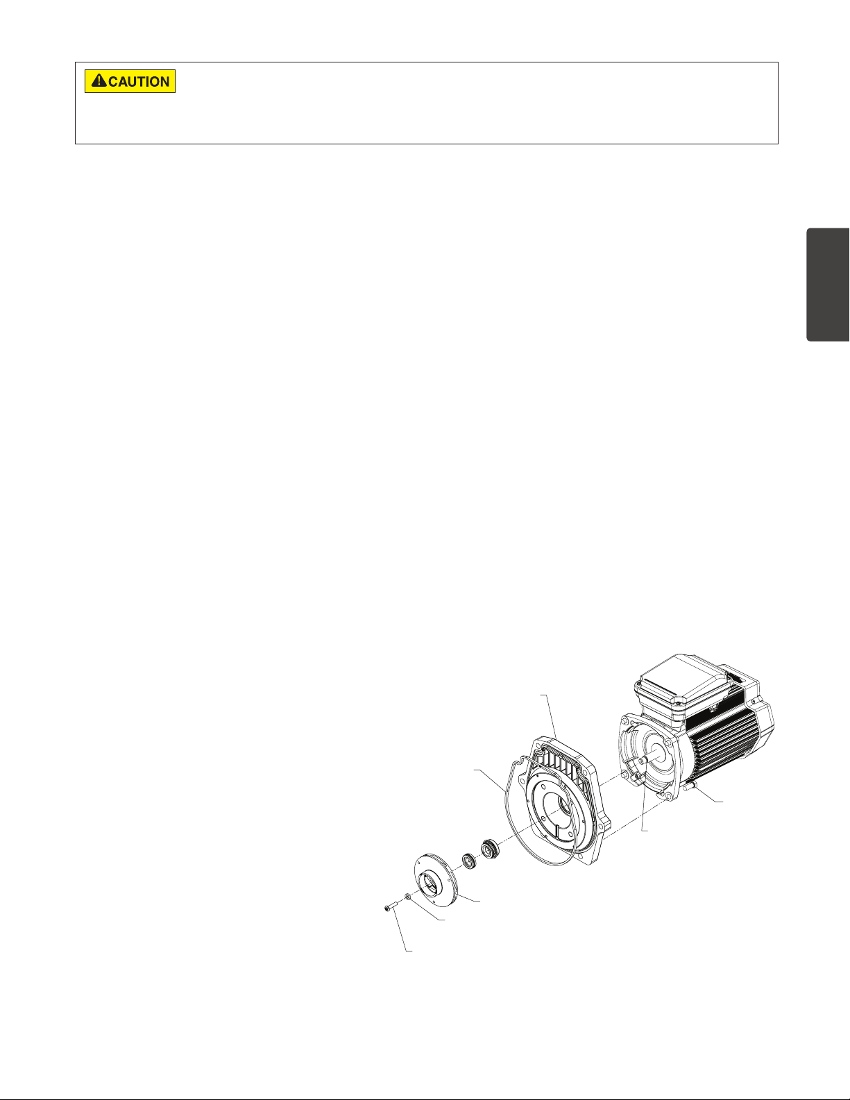
LOCKSCREW
DO NOT run the pump dry. If the pump is run dry, the mechanical seal will be damaged and the pump will start leaking. If this
occurs, the damaged seal must be replaced. ALWAYS maintain proper water level. If the water level falls below the suction port,
the pump will draw air through the suction port, losing the prime and causing the pump to run dry, resulting in a damaged seal.
Continued operation in this manner could cause a loss of pressure, resulting in damage to the pump case, impeller and seal and may cause property
damage and personal injury.
Pump Reassembly
1. When installing the replacement shaft seal, use
silicone sealant on the metal portion before
pressing into the seal plate, being careful to keep
off of the seal face. Ensure the seal is fully seated
and allow 24 hours for sealant to cure. (Complete
seal plate w/seal replacement kit available, P/N
350201/350101.)
2. Before installing the ceramic section of the seal into
the impeller, be sure the impeller is clean. Use a
light density soap and water to seal the seal. Press
the seal into the impeller with your thumbs and wipe
off the ceramic and carbon faces with a clean cloth.
3. Remount the seal plate to the motor by installing
bolts in an X pattern and tightening to 70 in-lbs.
4. Clean the motor shaft thread and the impeller
insert, then screw the impeller onto the motor shaft.
5. Screw in the impeller lock screw (counter-clockwise
and tighten to 25 in-lbs. while holding the motor
shaft with wrench).
6. Remount the diffuser onto the seal plate. Make
sure the plastic pins and holding screw inserts are
aligned.
7. Grease the diffuser O-ring and seal plate gasket.
8. Grease the bolt threads, assemble the motor subassembly to the strainer pot-pump body by using
the two through bolts for proper alignment. Do not
tighten the through bolts until all 6 bolts are in place
and finger tightened. Torque in a cross pattern to
110 in-lbs.
9. Fill the pump with water.
10. Reinstall the pump lid and plastic clamp;
see the next section, ‘Restart Instructions’.
11. Reprime the system.
Restart Instructions
If pump is installed below the water level of the pool,
close return and suction lines prior to opening hair and
lint pot on pump. Make sure to re-open valves prior to
operating.
Priming the Pump
The pump strainer pot must be filled with water before
the pump is initially started. Follow these steps to
prime the pump:
1. Remove the pump lid plastic clamp. Remove the
pump lid.
2. Fill the pump strainer pot with water.
3. Reassemble the pump cover and plastic clamp
onto the strainer pot. The pump is now ready to
prime.
4. Open the air release valve on the filter, and stand
clear of the filter.
5. Turn on the switch or time clock.
6. When water comes out of the air release valve,
close the valve. The system should now be free of
air and recirculating water to and from the pool.
7. For 2-speed pumps:
• Pump should run on high-speed for priming.
• The pump should not run longer than 8
minutes before priming is achieved.
SEAL PLATE
GASKET
ENGLISH
LOCKSREW SEAL
WHISPERFLO
IMPELLER
®
High Performance Pump Installation and User’s GuideWHISPERFLO
BOLT
MOTOR SHAFT
Motor Assembly
Page 10

6
TROUBLESHOOTING
Problem Possible Cause Corrective Action
Pump failure.
Reduced capacity and/or
head.
Pump will not prime - Air leak, too much air.
Pump will not prime - Not enough water.
Pump stainer gasket is clogged.
Pump strainer gasket is defective.
Air pockets or leaks in suction line.
Clogged impeller.
Pump strainer clogged.
Check suction piping and valve glands on any suction
gate valves. Secure lid on pump strainer pot and be
sure lid gasket is in place. Check water level to be
sure skimmer is not drawing air.
Be sure the suction lines, pump, strainer, and pump
volute are full of water. Be sure valve on suction line is
working and open (some systems do not have valves).
Check water level to make sure water is available
through skimmer.
Clean pump strainer pot.
Replace gasket.
Check suction piping and valve glands on any suction
gate valves. Secure lid on pump strainer pot and be
sure lid gasket is in place. Check water level to be
sure skimmer is not drawing air.
Turn off electrical power to the pump.
Disassemble (see page 4, ‘Pump Disassembly’)
Clean debris from impeller. If debris cannot be
removed, complete the following steps:
1. Remove left hand thread anti-spin bolt and o-ring.
2. Remove, clean, and reinstall impeller.
Reassemble (see page 5, ‘Pump Reassembly’)
Clean suction trap.
WHISPERFLO
®
High Performance Pump Installation and User’s Guide
Page 11
7
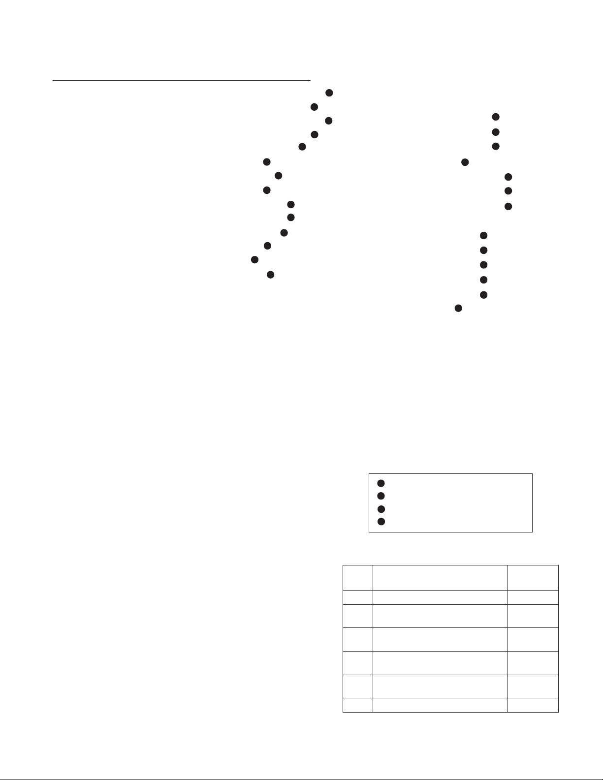
REPLACEMENT PARTS
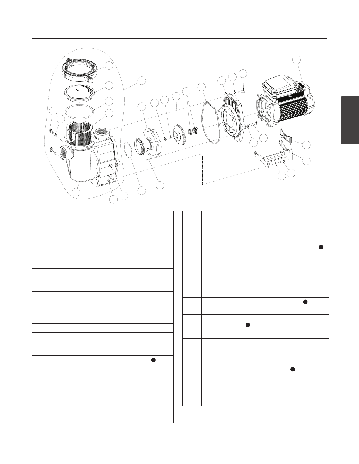
1
2
Item
No.
24
25
10
P/N Description
3
4
8
22
14
13
11
1 357199 Clamp, Cam & Ramp, Almond
1 357150 Clamp, Cam & Ramp, Black
2 357151 Cover, Clear, WFE Pump
2 357156 Cover, chemical resistant Cam & Ramp
3 350013 O-Ring, WFE Cover
4 070387 Strainer Basket, WFE
5 070430
Bolt, 3/8 - 16 x 1.25 Hex Head. SS, 4
Req.
6 072184 Washer, 3/8 x 13/16 O.D. SS, 6 Req.
7 070431
8
071403 Nut, 3/8, 16 Hex Head, 2 Req.
Bolt, 3/8 - 16 x 1.75 Hex Head. SS, 2
Req.
9 357100 Black Gasket for Seal Plate
10 357149
Volute & Seal Plate, Almond
Replacement Kit
10 350015 Volute, WFE Pump & Pot, Almond
10 357157 Volute, WFE Pump & Pot, Black
1
11 355227 O-Ring Parker No. 2-238, WFE Pump
12 071660 Set Screw, 4-40 x 1-1/8 WFE, 2 Req.
13 072928 Diffuser assembly, WFE-12, 3 HP Only
13 072927
Diffuser assembly, WFE 2-8,
1/2 HP-2.5 HP
14 071652 Set Screw, 1/4 - 20 x 1 in. Phillips
15 075713 Rubber Washer, WFE Pump
27
5
6
1826
9
1616
28
15
7
6
23
12
Item
No.
P/N Description
20
19
21
ENGLISH
16 071734S Seal PA-7 w/ ceramic seat, PS1000
16 071728 Seal A7 w/ ceramic seat, PS201
17 070429 Bolt 3/8 - 16 x 7/8 SS Hex Head, 4 Req.
18 350201
18 350101
Seal Plate Kit WFE Almond (Includes
Mechanical Seal installed) Items 9, 16 & 18
Seal Plate Kit WFE Black (Includes
Mechanical Seal installed) Items 16 & 18
1
19 070927 Foot, WFE Pump, Almond
19 357159 Foot, Black
20 070929 Foot Insert, WFE Pump, Almond
1
20 357160 Foot Insert, WFE Pump, Black
21 071657
Screw 1/4 - 20 x 1 In. Hex Head, SS,
1
2 Req.
22 071406 Nut, 1/4 - 20 Hex Head, SS, 2 Req.
23 072183 Washer, 1/4 x 5/8 OD, SS, 2 Req.
24 071131 Knob, Drain Plug, Almond, 2 Req.
24 357161 Knob, Drain Plug, Black, 2 Req.
25 192115 O-Ring, Drain Plug, 2 Req.
26 357149
- 357923Z
Volute/Seal Plate Replacement Kit, Almond
(Incl. Items: 1-4, 9, 10, 16, 18, 24, and 25)
Fan Guard Kit, TEFC/Super-Duty
1
27 See Motor Table on next page
WHISPERFLO
®
High Performance Pump Installation and User’s GuideWHISPERFLO
Page 12
8
Item
P/N Description
No.
Motors
27 355008S 3/4 HP, 60 Hz, WFE-2, 3 & 24, 1 spd., almond, 31 lbs.
27 355010S 1 HP, 60 Hz, WFE-4 & 26, 1 spd., almond, 33 lbs.
27 355012S 1-1/2 HP, 60 Hz, WFE-6 & 28, 1 spd., almond, 39 lbs.
27 355014S 2 HP, 60 Hz, WFE-8 & 30, 1 spd., almond, 40 lbs.
27 355016S 3 HP, 60 Hz, WFE-12, 1 spd., almond, 40 lbs.
27 356630S 1 HP, WFDS-4 & 26, 2 spd., 34 lbs.
4
27 071320S 1-1/2 HP, WFDS-6 & 28, 2 spd., 36 lbs.
27 071321S 2 HP, WFDS-8 & 30, 2 spd., 45 lbs.
4
27 355018S 1/2 HP, WF-2 & 23, 1 spd., almond, 39 lbs.
27 355020S 3/4 HP, WF-3 & 24, 1 spd., almond, 26 lbs.
27 355022S 1 HP, WF-4 & 26, 1 spd., almond, 28 lbs.
27 355024S 1-1/2 HP, WF-6 & 28, 1 spd., 39 lbs.
27 355026S 2 HP, WF-8 & 30, 1 spd., 32 lbs.
27 355033S 3 HP, WF-12, 1 spd., almond, 40 lbs.
3
3
3
2
4
3
3
3
27 355203S 1 HP, WFK-4, 3 ph, 1 spd., black, 28 lbs.
27 355204S 1-1/2 HP, WFK-6, 3 ph, 1 spd., black, 30 lbs.
27 355205S 2 HP, WFK-8, 3 ph, 1 spd., black, 37 lbs.
27 355398S 3 HP, WFK-12, 3 ph, 1 spd., black, 35 lbs.
27 356626S 1 HP, WFK-4, 3 ph, 1 spd., almond, 28lbs.
27 356627S 1-1/2 HP, WFK-6, 3 ph, 1 spd., almond, 30lbs.
27 356628S 2 HP, WFK-8, 3 ph, 1 spd., almond, 37 lbs.
27 356629S 3 HP, WFK-12, 3 ph, 1 spd., almond, 35 lbs.
27
27
354805S
354807S
1 HP, WFK-4, Super-Duty, 3 ph, 1 spd., almond, 28 lbs.
1-1/2 HP, WFK-6, Super-Duty, 3 ph., 1 spd., almond,
30lbs.
27
354809S
2 HP, WFK-8, Super-Duty, 3 ph., 1 spd., almond,
36 lbs.
27
354811S
3 HP, WFK-12, Super-Duty, 3 ph., 1 spd., almond,
39 lbs.
27
27
27
27
354821S
354823S
354815S
354817S
1 HP, WFET-4, TEFC, 1 ph., 1 spd., almond, 29lbs.
1-1/2 HP, WFET-6, TEFC, 1 ph., 1 spd., almond, 31lbs.
2 HP, WFET-8, TEFC, 1 ph., 1 spd., almond, 37lbs.
3 HP, WFET-12, TEFC, 1 ph., 1 spd., almond, 41lbs.
Power End Sub-assembly Includes
Items: 12-18, 27-28
2
2
2
2
075136 WFE-2
075137 WFE-3, WFE-24
075138 WFE-4, WFE-26
075139 WFE-6, WFE-28
075140
075141 WFE-12
WFE-8, WFE-30
2
075145 WFDS-3, WFDS-24
075142 WFDS-4, WFDS-26
075143 WFDS-6, WFDS-28
2
2
2
4
4
4
075144 WFDS-8, WFDS-30
075251 WF-2, WF-23
075252 WF-3, WF-24
075253 WF-4, WF-26
075254 WF-6,WF-28
075255 WF-8,WF-30
075256 WF-12
3
3
3
3
3
3
Fluid Ends-All Parts, w/o Motor
075451 WFE-2 fluid end, 1/2 HP
075452 WFE-3 fluid end, 3/4 HP
075453 WFE-4 fluid end, 1 HP
075454 WFE-6 fluid end, 1-1/2 HP
075455 WFE-8 fluid end, 2 HP
075456 WFE-12 fluid end, 3 HP
1
CSA/CUL (only) for Canada
2
Energy efficient, single phase
3
Standard efficiency, single phase
4
Two speed, single phase
Not Shown
79129900 2-Speed Toggle Switch
350202 Seal Plate Kit: Seal plate (almond), Gasket (black),
350203 Seal Plate Kit: Seal plate (black), Gasket (black), with
357244 Pot Assembly, Black NPT. (Includes items: 1-4, 10, 24
357243 Pot Assembly, Almond NPT. (Includes items: 1-4, 10,
WHISPERFLO
with installed Seal (Includes items: 9, 16, & 18)
installed Seal (Includes items: 9, 16, & 18)
[qty. 2], 25 [qty. 2]).
24 [qty. 2], 25 [qty. 2]).
®
High Performance Pump Installation and User’s Guide
Impeller Chart
HP PUMP MODEL
1/2 WFE-2, WF-2, WF-23, WFK-2 073126
3/4
1½
WFE-3, WFE-24, WF-3, WF-24,
WFK-3, WFDS-24
WFE-4, WFE-26, WFET-4, WF-4,
1
WF-26, WFK-4, WFDS-4, WFDS-26
WFE-6, WFE-28, WFET-6, WF-6,
WF-28, WFK-6, WFDS-6, WFDS-28
WFE-8, WFE-30, WFET-8, WF-8,
2
WF-30, WFK-8, WFDS-8, WFDS-30
3 WFE-12, WFET-12, WF-12, WFK-12 073131
PART NO.
STD
073127
073128
073129
073130
Page 13
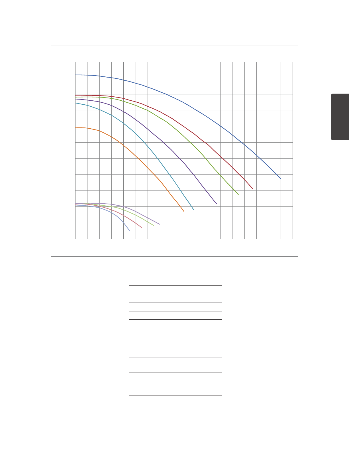
Pump Performance Curves
0
10
20
30
40
50
60
70
80
90
100
110
0102030405060708090100 110120 130140 150160 17 0180
TOTA L DYNAMIC HEAD IN FT OF WATER
WATER FLOW RATE IN US GALLONS PER MINUTE
E
F
G
H
I
J
D
C
B
A
WhisperFlo® High Performance Pump
9
ENGLISH
Curve Model
A WFDS-3, WFDS-24
B WFDS-4, WFDS-26
C WFDS-6, WFDS-28
D WFDS-8, WFDS-30
E WFE-2, WF-2, WF-23, WFK-2
F WFE-3, WFE-24, WF-3, WF-24,
WFK-3, WFDS-3, WFDS-24
G WFE-4, WFE-26, WFET-4, WF-4,
WF-26, WFK-4, WFDS-4, WFDS-26
H WFE-6, WFE-28, WFET-6, WF-6,
WF-28, WFK-6, WFDS-6, WFDS-28
I WFE-8, WFE-30, WFET-8, WF-8,
WF-30, WFK-8, WFDS-8, WFDS-30
J WFE-12, WFET-12, WF-12, WFK-12
WHISPERFLO
®
High Performance Pump Installation and User’s GuideWHISPERFLO
Page 14
®
WHISPERFLO
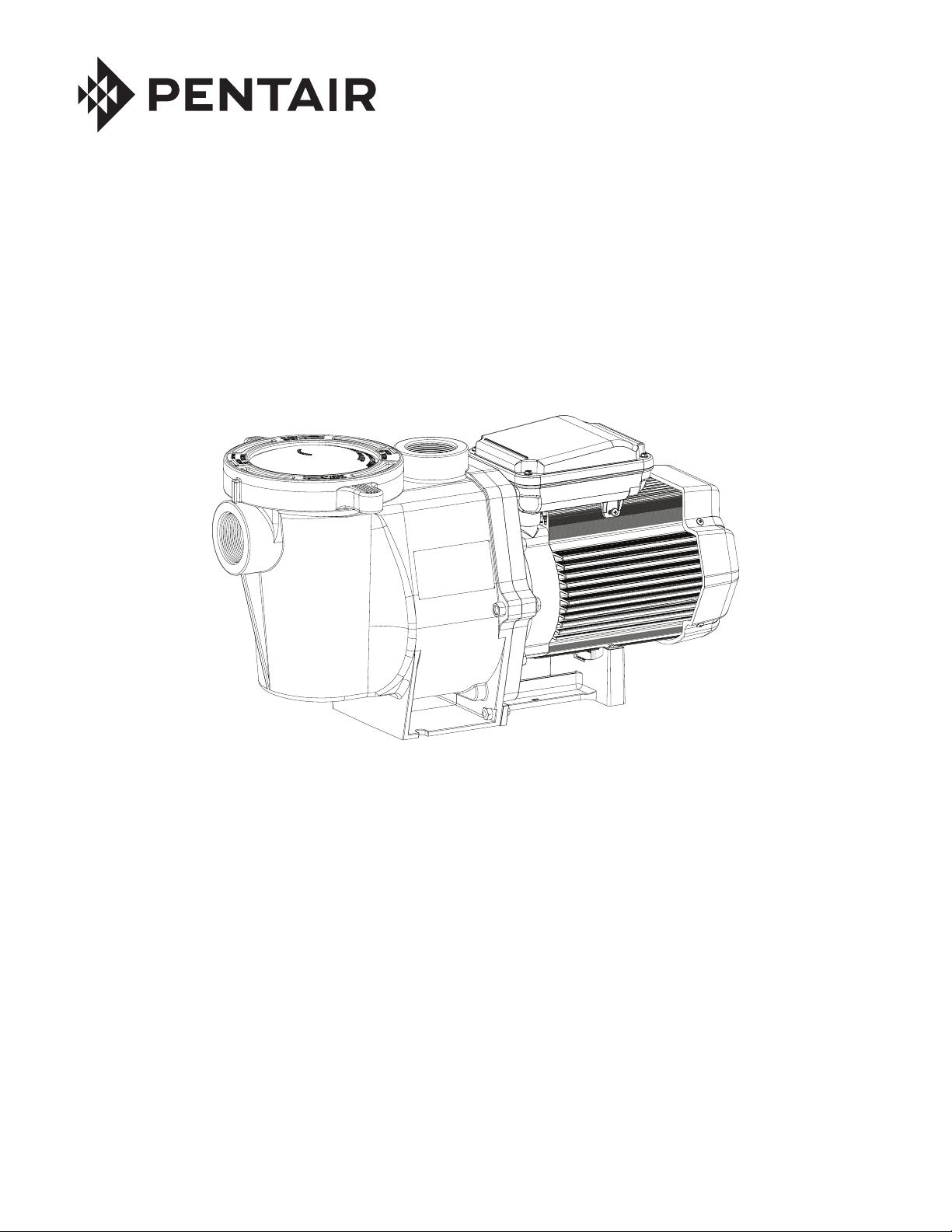
BOMBA DE ALTO RENDIMIENTO
GUÍA DE INSTALATIÓN
Y DEL USUARIO
INSTRUCCIONES IMPORTANTES DE SEGURIDAD
LEA Y SIGA TODAS LAS INSTRUCCIONES
GUARDE ESTAS INSTRUCCIONES
Page 15
ATENCIÓN AL CLIENTE / SOPORTE TÉCNICO
Si tiene alguna pregunta sobre cómo realizar pedidos de piezas de repuesto de Pentair Aquatic Systems, utilice la
siguiente información de contacto:
11
Servicio del Cliente y Soporte Técnico, USA
(de 8 a.m. a 4:30 p.m., Horario del Este y del Pacífico)
Teléfono: (800) 831-7133
Fax: (800) 284-4151
Sitio web
Visite www.pentairpool.com o www.staritepool.com
para encontrar información sobre los productos
Pentair.
ÍNDICE
Important Pump Warning and
Safety Instructions ................................................
Instalación ..............................................................
Ubicación
Tuberías
Conexiones y válvulas
Instalación eléctrica
Cableado
Conexión a tierra
Empalmes
Mantenimiento ........................................................
Canastilla del filtro de la bomba
Limpieza de la canastilla del filtro de la bomba
Acondicionamiento para el invierno
Sanford, Carolina del Norte
(de 8 a.m. a 4:30 p.m., Horario del Este)
Teléfono: (919) 566-8000
Fax: (919) 566-8920
Moorpark, California
(de 8 a.m. a 4:30 p.m., Horario del Pacífico)
Teléfono: (805) 553-5000 (Ext. 5591)
Fax: (805) 553-5515
Servicio ...................................................................
12
Cuidado del motor
14
14
14
14
15
15
15
15
Reemplazo del sello del eje
Desarmado de la bomba
Rearmado de la bomba
Instrucciones para encender de nuevo
Imprimar la bomba
Localizador de averías .........................................
Piezas de reemplazo .............................................
Curvas de la bomba
16
16
16
16
ESPAÑOL
17
17
17
17
18
18
18
19
20
22
© 2018 Pentair Water Pool and Spa, Inc. Todos los derechos reservados. Este documento está sujeto a cambios sin
previo aviso.
1620 Hawkins Ave., Sanford, NC 27330 • (919) 566-8000
10951 West Los Angeles Ave., Moorpark, CA 93021 • (805) 553-5000
Todos los logotipos y las marcas comerciales de Pentair son propiedad de Pentair, Inc. WhisperFlo® y High Flow™ son marcas
comerciales de Pentair Water Pool and Spa, Inc. y/o de sus compañías afiliadas en los Estados Unidos y/o en otros países. A
menos que se indique expresamente, los nombres y las marcas de terceros que se mencionan en este documento no indican
afiliación o aval alguno entre los propietarios de estos nombres y marcas y Pentair Water Pool and Spa, Inc. Es posible que estos
nombres y marcas sean marcas comerciales o registradas de estos terceros. Debido a que mejoramos continuamente nuestros
productos y servicios, Pentair se reserva el derecho a cambiar las especificaciones sin previo aviso. Pentair es una compañía que
ofrece igualdad de oportunidad de empleo.
P/N 071109 Rev. L 7/17/18
Guía de instalatión y del usuario de la bomba de alto rendimiento WHISPERFLO
®
Page 16
12
PELIGRO
PELIGRO
F
PELIGRO
ADVERTENCIAS E INSTRUCCIONES DE SEGURIDAD IMPORTANTES DE LA BOMBA
Advertencias generales
NOTA IMPORTANTE
Esta guía ofrece las instrucciones de instalación y operación para este producto.
Consulte a Pentair por cualquier pregunta relacionada con este equipo.
Atención, instalador: Esta guía contiene información importante sobre
la instalación, la operación y el uso seguro de este producto. Se le debe
proporcionar esta información al dueño y/u operador del equipo luego de la
instalación o se debe dejar esta información encima o cerca de la bomba.
Atención, usuario: Este manual contiene información importante que
le ayudará a operar y mantener este producto. Por favor, consérvelo para
futura referencia.
LEA Y SIGA
TODAS LAS INSTRUCCIONES
GUARDE ESTAS INSTRUCCIONES
Este es el símbolo de alerta de seguridad. Cuando vea
este símbolo en su sistema o en este manual, busque
una de las siguientes palabras de señal y esté alerta a
la posibilidad de que alguna persona resulte lesionada.
Advierte sobre peligros que pueden causar la muerte,
serias lesiones personales o daños importantes a la
propiedad si se ignoran.
Advierte sobre peligros que pueden causar la muerte,
serias lesiones personales o daños importantes a la
propiedad si se ignoran.
Advierte sobre peligros que pueden provocar lesiones
personales leves o daños a la propiedad si son
ignorados.
NOTA indica instrucciones especiales no relacionadas con peligros.
Lea y siga cuidadosamente todas las instrucciones de seguridad en este
manual y en relación a los equipos. Conserve las etiquetas de seguridad
en buenas condiciones; reemplácelas si faltan o están dañadas.
• Nunca se debe abrir el interior del recinto del motor del accionador.
Hay un bloque de condensadores con una carga de 230 VCA incluso
cuando la unidad no está conectada a la fuente de alimentación.
• La bomba no es sumergible.
• La bomba puede alcanzar caudales de salida elevados; tenga cuidado
al instalar y programar el límite potencial de rendimiento de las bombas
con equipos antiguos o dudosos.
• Los códigos requeridos para la conexión eléctrica varian dependiendo
del país, estado o municipalidad local. Instale el equipo de acuerdo al
código de electricidad nacional y todos los demás códigos y normas
aplicables.
• Antes de efectuar el mantenimiento de la bomba; apague la alimentación
de energía eléctrica a la bomba desconectando el circuito principal
que va hacia la bomba.
• Este artefacto no debe ser utilizado por personas (incluyendo niños)
con capacidades físicas, sensoriales o mentales reducidas, o que no
tengan la experiencia y los conocimientos, a menos que hayan sido
supervisados o instruidos en el uso del artefacto por una persona
responsable por su seguridad.
EL INCUMPLIMIENTO DE TODAS LAS
INSTRUCCIONES Y ADVERTENCIAS PUEDE DAR
COMO RESULTADO LESIONES CORPORALES SERIAS O LA MUERTE.
ESTA BOMBA DEBE SER INSTALADA Y MANTENIDA ÚNICAMENTE POR
UN PROFESIONAL DE MANTENIMIENTO DE PISCINAS CUALIFICADO.
LOS INSTALADORES, OPERADORES DE PISCINAS Y DUEÑOS DEBEN
LEER ESTAS ADVERTENCIAS Y TODAS LAS INSTRUCCIONES EN
EL MANUAL DEL USUARIO ANTES DE USAR ESTA BOMBA. ESTAS
ADVERTENCIAS Y EL MANUAL DEL USUARIO DEBEN QUEDARSE
CON EL DUEÑO DE LA PISCINA.
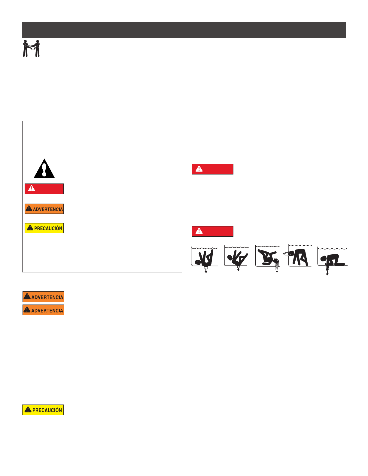
PELIGRO DE ATASCAMIENTO: ¡MANTÉNGASE
ALEJADO DEL DRENAJE PRINCIPAL Y DE TODAS
LAS SALIDAS DE SUCCIÓN!
Cuando instale y use estos equipos eléctricos, siempre se deben seguir las
precauciones de seguridad básicas, entre las que se incluye las siguientes:
No permita que los niños usen este producto.
RIESGO DE DESCARGA ELÉCTRICA. (Para todas las
unidades instaladas de manera permanente, diseñadas
para usarse en circuitos derivados monofásicos de 15 o 20 amperes y 125 a 240
voltios). Conecte solamente a un circuito derivado protegido por un interruptor
de circuito por falla a tierra (GFCI). Contacte a un electricista cualificado si no
puede verificar que el circuito esté protegido por un GFCI. Esta unidad debe
conectarse solamente a un circuito de alimentación protegido por un interruptor
de circuito por falla a tierra (GFCI). Dicho GFCI debe proporcionarlo el instalador
y debe ser sometido a pruebas de rutina. Para probar el GFCI, oprima el botón
de prueba. El GFCI debe cortar la energía. Oprima el botón de reanudar.
La energía debería restaurarse. Si el interruptor de circuito por falla a tierra
(GFCI) no puede funcionar de esta manera, el GFCI es defectuoso. Si el GFCI
interrumpe la alimentación a la bomba sin haberse oprimido el botón de prueba,
estará fluyendo una corriente a tierra, indicando la posibilidad de un choque
eléctrico. No use esta bomba. Desconecte la bomba y pídale a un representante
de servicio cualificado que corrija el problema antes de usarla.
Esta bomba es para ser utilizada en piscinas
permanentes y también puede usarse con jacuzzis y
spas, si así se especifica. No la use con piscinas que se deban almacenar.
Una piscina instalada permanentemente se construye en el suelo o en un
edificio de manera tal que no se pueda desmontar para ser almacenada.
Una piscina que se debe almacenar está construida con el fin de poder
desmontarla fácilmente para su almacenamiento y montarla nuevamente
con posterioridad.
Guía de instalatión y del usuario de la bomba de alto rendimiento WHISPERFLO
ESTA BOMBA PRODUCE ALTOS NIVELES DE SUCCIÓN Y CREA UN
FUERTE VACÍO EN EL DRENAJE PRINCIPAL, EN LA PARTE INFERIOR
DE LA MASA DE AGUA. LA SUCCIÓN ES TAN FUERTE QUE PUEDE
ATRAPAR A ADULTOS O NIÑOS BAJO EL AGUA SI SE ENCUENTRA
PRÓXIMOS A UN DRENAJE O A UNA CUBIERTA O REJILLA ROTA O
SUELTA DEL DRENAJE.
EL USO DE CUBIERTAS INADECUADAS O PERMITIR EL USO DE LA
PISCINA O EL SPA CUANDO HAY CUBIERTAS AUSENTES, FISURADAS
O ROTAS PUEDE DAR COMO RESULTADO EL ATASCO DE ALGUNA
PARTE DEL CUERPO O ARTICULACIÓN, ENREDO DE CABELLO,
ATASCO DEL CUERPO, EVISCERACIÓN Y/O LA MUERTE.
La succión en el drenaje o salida puede causar:
Atascamiento de un miembro: Cuando un miembro del cuerpo es
succionado o insertado en una abertura y produce una obstrucción o
atrapamiento mecánico. Este peligro se presenta cuando la cubierta de
un drenaje falta, está rota, suelta, fisurada o incorrectamente asegurada.
Enredo de cabellos: Cuando el cabello se enreda o anuda en la cubierta del
drenaje y atrapa al nadador debajo del agua. Este peligro se presenta cuando
la velocidad del flujo de la cubierta es demasiado baja para la(s) bomba(s).
Atascamiento del cuerpo: Cuando una parte del cuerpo queda atrapada
contra la cubierta del drenaje manteniendo al nadador debajo del agua.
Este peligro se presenta cuando la cubierta del drenaje falta, está rota o
cuando la velocidad de flujo de la cubierta no es lo suficientemente alta
para la(s) bomba(s).
Evisceración/desentrañamiento: Cuando una persona se sienta en una
piscina abierta (particularmente una piscina de chapoteo para niños) o en la
salida de un spa y se aplica la succión directamente a los intestinos, causando
un daño intestinal severo. Este peligro se presenta cuando la cubierta del drenaje
falta, está suelta, fisurada o incorrectamente asegurada.
®
Page 17
13
PELIGRO
ADVERTENCIAS E INSTRUCCIONES DE SEGURIDAD IMPORTANTES DE LA BOMBA
Atrapamiento mecánico: Cuando las joyas, el traje de baño, los accesorios
para el cabello, lo dedos de manos o pies, o un nudillo se atascan en la abertura
de una salida o de una cubierta de drenaje. Este peligro se presenta cuando la
cubierta del drenaje falta, está suelta, rota, fisurada o incorrectamente asegurada.
NOTA: TODA LA FONTANERÍA DE SUCCIÓN DEBE INSTALARSE
EN CONFORMIDAD CON LOS ÚLTIMOS CÓDIGOS, ESTÁNDARES Y GUÍAS
NACIONALES Y LOCALES.
PARA MINIMIZAR EL RIESGO DE LESIONES DEBIDO
AL PELIGRO DE ATASCO POR SUCCIÓN:
• Para cada drenaje, se debe usar una cubierta de succión anti-atascos
apropiadamente instalada y asegurada y aprobada por el ANSI/ASME A112.19.8.
• Cada cubierta de succión debe ser instalada al menos a tres pies (3’) de
distancia, medidos desde el punto más cercano hasta el punto más cercano.
• Inspeccione todas las cubiertas con regularidad en busca de fisuras, daños e
intemperización avanzada.
• Si una cubierta está suelta, fisurada, dañada, rota o ausente, reemplácela con
una cubierta certificada apropiada.
• Reemplace la cubierta del drenaje según sea necesario. Las cubiertas del drenaje
se deterioran con el tiempo debido a la exposición a la luz solar y el clima.
• Evite que el cabello, los miembros superiores e inferiores o el cuerpo estén en
proximidad cercana a las cubiertas de succión, el drenaje o la salida de la piscina.
• Deshabilite las salidas de la succión o vuelva a configurar las entradas de retorno.
La Ley de Seguridad para Piscinas y Spas Virginia Graeme Baker (VGB) crea
nuevos requerimientos para los dueños y operadores de piscinas y spas comerciales.
Las piscinas o spas comerciales construidos el 19 de diciembre de 2008 o después
de esa fecha, deberán utilizar:
(A) Un sistema de drenaje principal sin capacidad de aislamiento con cubiertas
de salida de succión que cumplan con el ASME/ANSI A112.19.8a en relación a
aditamentos de succión para uso en piscinas, piscinas de chapoteo, spas y jacuzzis,
y, ya sea:
(i) Un sistema de liberación de vacío de seguridad (SVRS) que cumpla con el estándar
ASME/ANSI A112.19.17 de sistemas de seguridad de liberación del vacío (SVRS)
fabricados para sistemas de piscina, spa, jacuzzi y piscina de niños residenciales
y comerciales, y/o la especificación del estándar ASTM F2387 para sistemas de
seguridad de liberación del vacío (SVRS) fabricados para piscinas, spas y jacuzzis o
(ii) Un sistema de ventilación limitado por succión debidamente diseñado y
comprobado o
(iii) Un sistema de apagado de bomba automático.
Las piscinas o spas comerciales construidos antes del 19 de diciembre de 2008, con
una sola salida de succión sumergida deberán usar una cubierta de la salida de la
succión que cumpla con el ASME/ANSI A112.19.8a y, ya sea:
(A) Un sistema de liberación de vacío de seguridad (SVRS) que cumpla con las
normas ASME/ANSI A112.19.17 y/o ASTM F2387, o
(B) Un sistema de ventilación limitado por succión debidamente diseñado y
comprobado, o
(C) Un sistema de apagado de bomba automático, o
(D) Bocas sumergidas desactivadas, o
(E) Las salidas de succión se deben configurar nuevamente como entradas de retorno.
Para la instalación de los controles eléctricos en la plataforma del equipo
(interruptores de encendido/apagado, temporizadores y centro de carga
automatizada)
Instale todos los controles eléctricos en la plataforma del
equipo, como los interruptores de encendido/apagado (ON/
OFF), los cronómetros y los sistemas de control, etc. para
permitir la operación (arranque, cierre o mantenimiento)
de cualquier bomba o filtro para que el usuario no coloque
ninguna porción de su cuerpo sobre o cerca de la tapa
coladora de la bomba, la tapa del filtro o los cierres de
la válvula. Esta instalación debe otorgar al usuario suficiente espacio para
mantenerse alejado del filtro y la bomba durante el arranque del sistema, el cierre
o el mantenimiento del filtro del sistema.
Debe haber un interruptor de cierre de emergencia
claramente etiquetado para la bomba en un lugar obvio
y de fácil acceso. Asegúrese que los usuarios sepan dónde está y cómo usarlo
en caso de emergencia.
Guía de instalatión y del usuario de la bomba de alto rendimiento WHISPERFLO
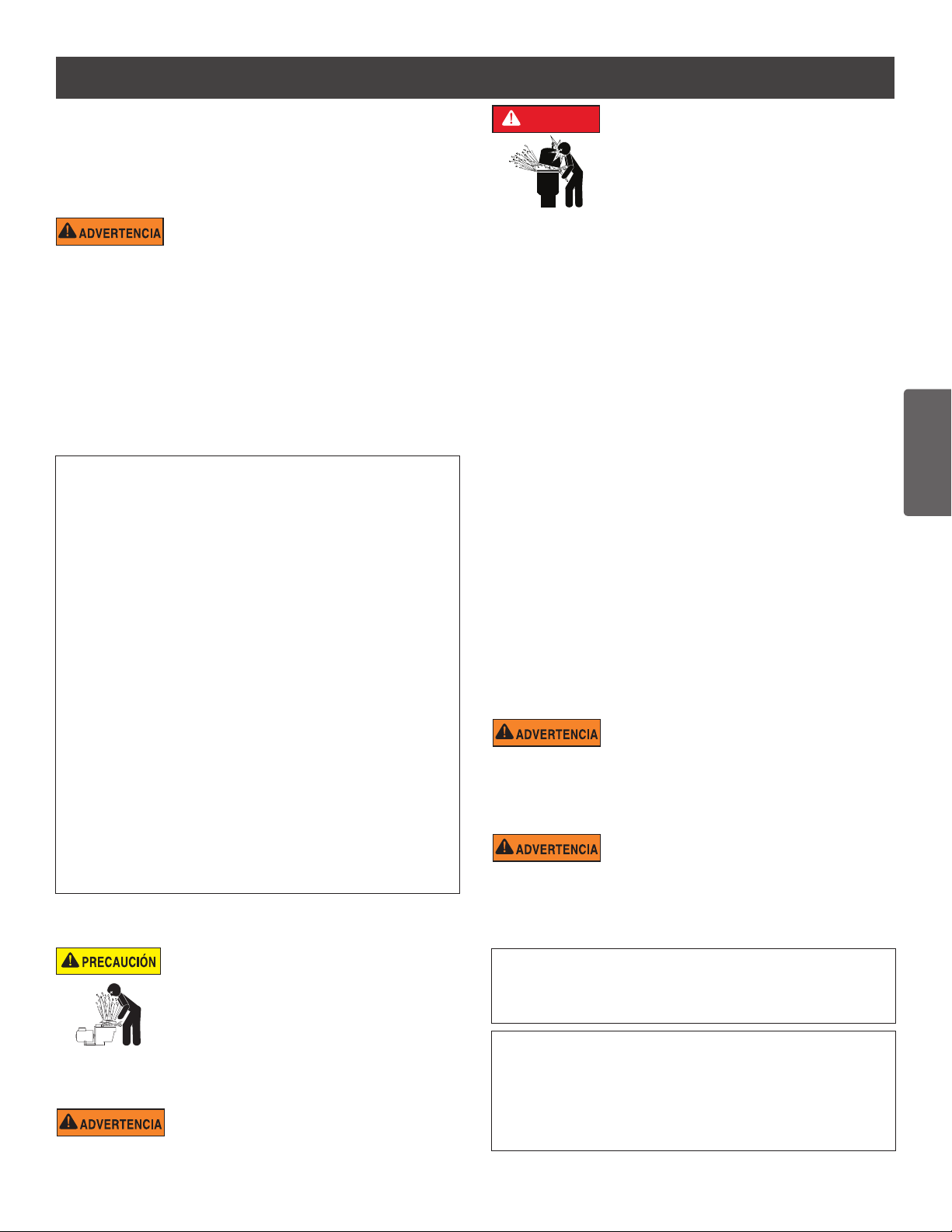
PRESIÓN PELIGROSA: MANTENGA DISTANCIA DE
LA BOMBA Y EL FILTRO DURANTE EL ARRANQUE
Los sistemas de circulación funcionan bajo alta presión.
Cuando se hace mantenimiento a una parte del sistema
de circulación (es decir, el anillo de bloqueo, la bomba,
el filtro, las válvulas, etc.), el aire puede ingresar al
sistema y presurizarse. El aire presurizado puede hacer
que las válvulas y la tapa del filtro de la cubierta de la carcasa de la bomba se
separen violentamente, lo que puede ocasionar lesiones personales severas
o la muerte. La tapa del tanque del filtro y la cubierta del colador deben estar
correctamente aseguradas para evitar la separación violenta. Manténgase
alejado de los equipos del sistema de circulación de aire cuando encienda o
haga arrancar la bomba.
Antes de efectuar el mantenimiento a los equipos, tome nota de la presión del
filtro. Asegúrese de que todos los controles estén configurados para garantizar
que el sistema no arranque inadvertidamente durante el mantenimiento. Apague
toda alimentación a la bomba. IMPORTANTE: Coloque la válvula manual
de alivio de aire del filtro en posición abierta y espere que se alivie toda
la presión que se encuentra en el sistema.
Antes de hacer arrancar el sistema, abra completamente la válvula manual de
alivio de aire y coloque todas las válvulas del sistema en la posición abierta
para permitir que el agua fluya libremente desde el tanque y de regreso a él.
Manténgase alejado de todos los equipos y encienda la bomba.
IMPORTANTE: No cierre la válvula manual de alivio de aire del filtro hasta
que toda la presión haya sido descargada de la válvula y que aparezca
una corriente constante de agua. Observe el medidor de presión del filtro y
asegúrese de que no sea más alta que la condición previa al mantenimiento.
Información de instalación general
• Todo el trabajo debe realizarlo un profesional de servicio cualificado, y debe
cumplir con todos los códigos nacionales, estatales y locales.
• Instale de manera tal que haya drenaje del compartimiento para los
componentes eléctricos.
• Estas instrucciones contienen información para una variedad de modelos
de bombas y por tanto algunas instrucciones podrían no aplicarse a un
cierto modelo específico. Todos los modelos han de usarse en piscinas. La
bomba funcionará correctamente solamente si tiene el tamaño adecuado
en relación a la aplicación y si está apropiadamente instalada.
Las bombas de tamaño incorrecto o mal instaladas
o que se usen con aplicaciones diferentes a las que
fueron diseñadas para la bomba pueden provocar graves lesiones personales
o la muerte. Estos riesgos pueden incluir, entre otros, choques eléctricos,
incendios, inundaciones, atascamientos por succión o lesiones graves o
daños a la propiedad provocados por una falla estructural de la bomba u otro
componente del sistema.
La bomba puede producir altos niveles de succión del
lado de la succión del sistema de conexiones. Estos
niveles elevados de succión pueden representar un riesgo si una persona
se encuentra muy cerca de las aberturas de succión. La persona puede
lesionarse seriamente debido a este alto nivel de vacío, o puede atascarse y
ahogarse. Es absolutamente crítico que las conexiones de succión se instalen
de acuerdo con los códigos nacionales y locales para piscinas más recientes.
Las bombas y los motores de repuesto con velocidad única y un
(1) HP total o superior no se pueden vender, poner a la venta o
instalar en un grupo residencial para su uso en California, Título
20 del CCR, secciones 1601-1609.
Las advertencias y las instrucciones de seguridad para las bombas y otros
productos relacionados de Pentair Water Pool and Spa, Inc. se encuentran
disponibles en:
http://www.pentairpool.com/pool-owner/safety-warnings/ o llame al
(800) 831-7133 para obtener copias adicionales y gratuitas de las instrucciones.
Consulte en http://www.pentairpool.com/pool-owner/safety-warnings/ para
ver las instrucciones de advertencia y seguridad relacionadas con este producto.
Warning Page P/N 352557 Rev. C 7/18
ESPAÑOL
®
Page 18

14
INSTALACIÓN
Sólo personal de servicio calificado debe instalar la bomba WhisperFlo®. Consulte la sección “Instrucciones de seguridad
y advertencias de la bomba” en las páginas 11 a 12 para obtener información adicional sobre pautas para la instalación
y la seguridad.
Ubicación
1. Instale la bomba lo más cerca posible a la piscina o
spa. Para reducir la pérdida de fricción y mejorar la
eficacia, use un mecanismo de succión corta y directa
y retornos de tuberías.
2. Realice la instalación a un mínimo de 5 pies (1,52 m.)
de la pared interior de la piscina y el spa. En Canadá,
las instalaciones deben estar como mínimo a una
distancia de 9,8 pies (3 metros) del agua de la piscina.
3. Instale la bomba a un mínimo de 3 pies (0,9 metros)
de la salida del calefactor.
4. No instale la bomba a más de 10 pies (2,44 m) por
encima del nivel del agua.
5. Instale la bomba en un área cubierta y bien ventilada
para protegerla de la humedad excesiva (es decir,
lluvia, sistemas de aspersión, etc.)
6. Instale la bomba con una distancia de separación
trasera de al menos 3 pulgadas (76,2 mm) de
manera que el motor pueda ser extraído fácilmente
cuando debe ser reparado y cuando se realice el
mantenimiento.
Distancia de seguridad de la parte trasera
de la bomba
DIÁMETRO DE EMPALME DE 5 x
CODO
Recomendado mínimo Diámetro de empalme
3 PULG.
(76,2CM)
DE MÍNIMO
Tuberías
1. P
ara una mejor plomería en la piscina, se recomienda
utilizar un tamaño de tubería más grande. Cuando
instale los accesorios para entradas y salidas
(adaptadores macho), use un sellador de roscas.
2. Utilice tamaños de caños más grandes para una mejor
tubería. El diámetro de empalme debe ser el mismo o
mayor que el diámetro de la línea de retorno.
3. Las tuberías en el lado de succión de la bomba deben
ser lo más cortas posibles.
4. Para la mayoría de las instalaciones que Pentair
recomienda instalar una válvula en la aspiración de
la bomba y mangueras de retorno para que la bomba
puede ser aislada durante el mantenimiento rutinario.
Sin embargo, recomendamos que una válvula, codo o
tee instalado en la línea de succión debe ser no más
cerca de la parte delantera de la bomba de cinco 5
veces la línea de succión de diámetro.
Ejemplo: Un tubo de 2 pulgadas requiere una
distancia de 10 pulgadas (25.4 cm) del frente de la
entrada de succión de la bomba. Esto ayudará a que
la bomba cebe más rápido y dure más.
Nota: No instale codos de 90° directamente en la
entrada o toma de corriente de la bomba.
Conexiones y Válvulas
1. No instale codos de 90° directamente en la entrada
de la bomba.
2. L
os sistemas de succión deberían tener válvulas de
compuertas instaladas en las tuberías de succión y
descarga para mantenimiento; sin embargo, la válvula
de compuerta de succión no debe estar más cerca
que cinco veces el diámetro de la tubería de succión
como se describe en el párrafo anterior.
3. Utilice una válvula de retención en la línea de
descarga al utilizar esta bomba para cualquier
aplicación donde hay altura significativa de la tubería
después de la bomba.
4. Asegúrese de instalar las válvulas de comprobación
cuando nivela en paralelo con otra bomba. Esto ayuda
a evitar la rotación inversa del propulsor y el motor.
Guía de instalatión y del usuario de la bomba de alto rendimiento WHISPERFLO
®
Page 19
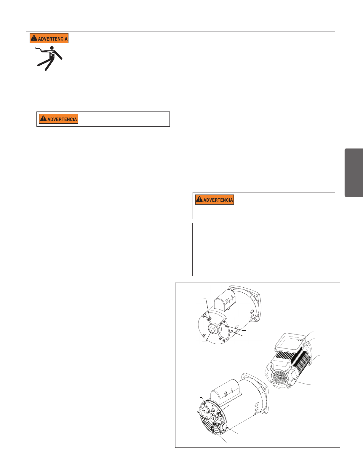
Instalación eléctrica
Lengüeta de empalme
Lengüeta de
empalme
Tornillo a tierra
Receptáculo con
tubo de 1/2" NPT
para conector de
líquido
Bridas del eje
del motor para
llave de 1/2”
Tornillo a tierra
Receptáculo con
tubo de 1/2" NPT
para conector de
RIESGO DE DESCARGA ELÉCTRICA O ELECTROCUCIÓN. Esta bomba debe ser instalada por un electricista con licencia o certificado o
por un profesional de servicios calificado conforme al Código Nacional de Electricidad (NEC) y los códigos y las ordenanzas locales aplicables.
Una instalación inadecuada generará un riesgo eléctrico que podría causar la muerte o lesiones graves a usuarios, instaladores y otras
personas debido a una descarga eléctrica, y también podría provocar daños a la propiedad.
Desconecte siempre la bomba desde el interruptor de circuito antes de realizarle el servicio. No hacerlo podría causar la muerte o
lesiones graves a las personas que realizan el servicio, a los usuarios u otras personas debido a una descarga eléctrica.
Lea todas las instrucciones de servicio antes de trabajar en la bomba.
15
Cableado
1. Verifique que todos los interruptores, disyuntores y controles
automáticos estén apagados antes de conectar el motor.
CARGA GUARDADA: espere al menos sesenta
(60) segundos antes de realizar el servicio.
2. Conozca el diagrama de cableado, los voltios, hertz,
amperios y fases del motor de su bomba en particular. Toda
la información figura en la placa de identificación que está
sobre un lado del motor.
3. Verifique que la tensión de alimentación cumpla con los
requisitos que aparecen en la placa del motor. Si no se
cumplen, se puede producir un daño permanente en el motor.
4. Para conocer el calibre de los cables y las pautas
generales para una instalación eléctrica adecuada, siga
las especificaciones definidas por el Código Nacional de
Electricidad y cualquier otro código nacional o local de
aplicación.
5. Los motores trifásicos necesitan protección externa contra
golpes de tensión. Es necesario hacer una inspección inicial
para garantizar que la bomba rote correctamente.
Una vez instalada, inicie el ciclo momentáneamente. Para ello
enciéndala y apáguela. Observe la rotación del ventilador o
del eje del motor cuando se detiene. Si está correctamente
conectado, el eje y/o el ventilador coincidirán con la flecha
de rotación que tiene la bomba.
6. Use un aliviador de tensión y verifique que todas las
conexiones eléctricas estén limpias y ajustadas.
7. Corte los cables de la longitud apropiada para que no
se superpongan ni entren en contacto al momento de
conectarlos.
Empalmes
1. Empalme el motor a la estructura según el Código Nacional
de Electricidad y todos los códigos nacionales o locales de
aplicación. Utilice un conductor de empalme de cobre sólido no
inferior a 8 AWG. Para las instalaciones canadienses se debe
usar un conductor de empalme de cobre sólido de 6 AWG o
más. Instale un cable desde el tornillo o la lengüeta de empalme
externos hasta la estructura de empalme.
2. Conecte el cable de la lengüeta de empalme accesible del motor
a todas las partes metálicas de la estructura de la piscina, el
spa o el jacuzzi y a todos los equipos eléctricos, conductos de
metal y tuberías de metal que estén a unos 5 pies (1.52 metros)
de las paredes internas de la piscina, el spa o el jacuzzi. Instale
un cable desde el tornillo o la lengüeta de empalme externos
hasta la estructura de empalme.
Antes de conectar o reconectar la bomba verifique
que todas las conexiones eléctricas estén firmes
y todas las cubiertas compartimientos eléctricos y de cableado estén
correctamente instaladas.
Nota: Cuando la bomba se arranque o se detenga cortándole la
energía con un relé o temporizador, se deberá usar un dispositivo
de dos polos para aplicar y quitar la energía a ambos TERMINALES
DEL CABLE DE ENERGÍA.
Pentair ofrece interruptores GFCI que ofrecen la protección
personal adecuada y además cumplen con las normas de NEC
de 2008 a la fecha para bombas para piscina. Vea el catálogo de
productos Pentair para obtener más detalles.
ESPAÑOL
Conexión a tierra
1. Conecte el motor a tierra de forma permanente mediante
el tornillo verde de conexión a tierra, como se muestra
debajo. Use el calibre y tipo de cable correctos, según lo
especifica el Código Nacional de Electricidad. Verifique
que el cable a tierra esté conectado a una conexión a
tierra del servicio eléctrico.
2. La bomba debe estar conectada permanentemente a un
interruptor de circuito, un temporizador de 2 polos o a un
relé de 2 polos.
Nota: Si la CA se obtiene de un interruptor de circuito
GFCI, el cableado de la bomba debe tener su propio
circuito independiente a menos que la bomba opere en
conjunto con un clorinador de sal de Pentair.
Section P/N 350486 Rev. C 8/24/17
Guía de instalatión y del usuario de la bomba de alto rendimiento WHISPERFLO
Bridas del
eje del motor
para llave de
1/2”
Tornillo
a tierra
Receptáculo con
tubo de 1/2" NPT
para conector de
líquido
líquido
Lengüeta
de empalme
Bridas del eje del
motor para llave
Allen de 1/4”
®
Page 20
16
MANTENIMIENTO
NO abra el depósito del filtro si el cebado de la bomba falla o si la bomba ha estado funcionando sin agua en el depósito del filtro.
Las bombas que funcionan en estas circunstancias pueden experimentar una acumulación de presión de vapor y pueden contener
agua caliente escaldada. Si abre la bomba puede resultar herido de gravedad. Para evitar la posibilidad de lesiones personales, asegúrese de que las
válvulas de succión y descarga estén abiertas y la temperatura del depósito del filtro esté fría para el tacto, luego ábrala con extrema precaución.
Para evitar el daño de la bomba y para un adecuado funcionamiento del sistema, limpie el filtro de la bomba y las canastillas de los
desnatadores con regularidad.
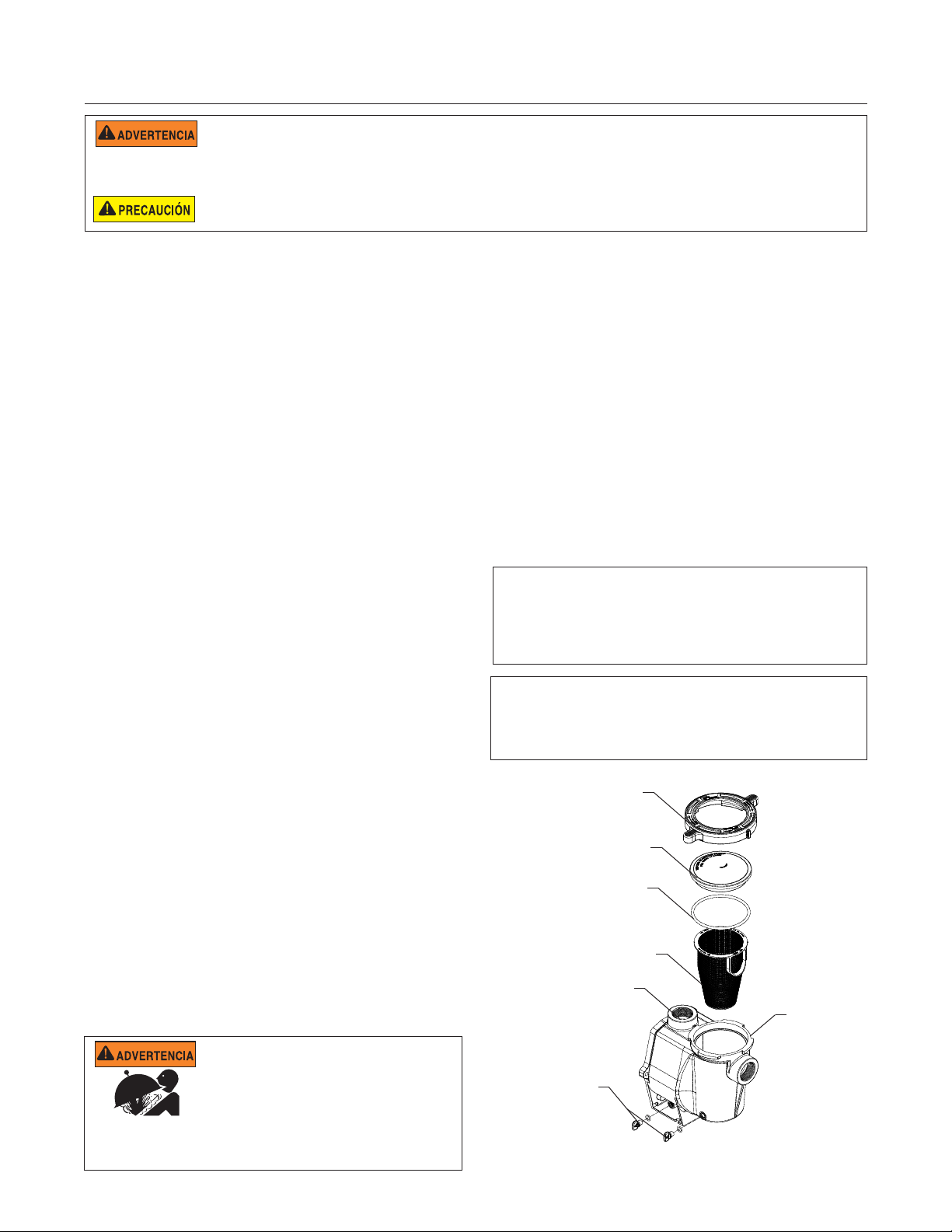
Canastilla del filtro de la bomba
La canastilla del filtro (o "depósito del filtro") se encuentra
enfrente del alojamiento de la bomba. La canastilla del
filtro debe mantenerse limpia y sin suciedad. Inspeccione
la canastilla a través de la tapa en la parte superior del
alojamiento.
Asegúrese de inspeccionar visualmente la canastilla del
filtro cada 1 a 4 semanas. Las canastillas del filtro sucias
reducen la eficiencia del filtro y del calefactor y ejercen
una presión anormal sobre el motor de la bomba. La
acumulación de bacterias puede ensuciar la tapa.
Limpieza de la canastilla del filtro de la bomba
1. Apague la bomba en el interruptor de circuito.
2. Libere presión en el sistema.
3. Gire la tapa y abrazadera en el sentido contrario a las
agujas del reloj y retírelas de la bomba.
4. Retire los residuos y limpie la canastilla. Reemplace la
canastilla si está rajada.
5. Vuelva a colocar la canastilla en la caja. Asegúrese de
alinear la perforación en la parte inferior de la canastilla
con el acanalado en la parte inferior del alojamiento.
Acondicionamiento para el invierno
Usted es responsable de determinar cuándo es probable
que se produzcan condiciones de congelamiento. Si
se esperan temperaturas muy bajas, siga los pasos
a continuación para reducir el riesgo de daños por
congelamiento. Los daños por congelamiento no
están cubiertos por la garantía.
Para evitar los daños por congelamiento, siga los
procedimientos a continuación:
1. Apague la corriente eléctrica de la bomba en el
disyuntor.
2. Retire los dos tapones de drenaje manual de
la carcasa para drenar el agua de la carcasa
de la bomba. Coloque los tapones en la canasta
de la bomba.
3. Cubra el motor para protegerlo de lluvia fuerte, nieve
y escarcha.
Nota: No envuelva el motor con plástico u otros materiales
hermetizados durante el almacenamiento de invierno.
El motor puede estar cubierto durante una tormenta, el
almacenamiento de invierno, etc., pero nunca cuando esté
funcionando o se espere que comience a funcionar.
6. Llene el depósito y el alojamiento de la bomba hasta
el puerto de entrada con agua.
7. Limpie la tapa y la abrazadera, el anillo tórico y la
superficie de sellado del depósito de la bomba.
Nota: Es importante que mantenga el anillo tórico de
En zonas de climas moderados, en caso de
posibles condiciones de congelamiento temporales,
haga funcionar el equipo de filtro toda la noche
para evitar el congelamiento.
la tapa limpio y bien lubricado.
8. Vuelva a instalar la tapa colocando la abrazadera y la
tapa en el depósito. Asegúrese de que el anillo tórico
Abrazadera, depósito
de la tapa esté bien colocado.
Coloque la abrazadera y la tapa sobre la bomba, luego
gire en sentido de las agujas del reloj hasta que las
manijas del anillo de seguridad estén horizontales.
9. Encienda la bomba en el interruptor de circuito.
10. Abra la válvula de alivio de aire manual en la parte
superior del filtro. Aléjese del filtro.
11. Espere hasta que se libere toda la presión. Ponga en
Canastilla del filtro
marcha la bomba.
12. Purgue el aire del filtro hasta que un flujo constante
Alojamiento
de agua salga de la válvula de alivio de aire del filtro.
Cierre la válvula de alivio de aire manual.
ESTE SISTEMA OPERA BAJO ALTA PRESIÓN.
Cuando cualquier parte del sistema de circulación
(es decir anillo de seguridad, bomba, filtro, válvulas,
etc.) está siendo controlado por el servicio técnico,
es posible que ingrese aire al sistema y que éste se
presurice. El aire presurizado puede causar que la tapa se separe, lo que
puede provocar heridas graves, la muerte o daño a la propiedad. A fin de
evitar este riesgo potencial, siga las instrucciones que se mencionan arriba.
Guía de instalatión y del usuario de la bomba de alto rendimiento WHISPERFLO
Tapón para
drenajes
Tapa
Anillo tórico
Conjunto del depósito del filtro
®
Depósito
Page 21
17
SERVICIO
Siempre desconecte la energía hacia la bomba en el interruptor de circuito antes de realizar el servicio a la bomba. Si no se hace
esto, las personas que realizan el servicio, los usuarios u otras personas pueden resultar muertas o con heridas de gravedad debido
al electrochoque. Lea todas las instrucciones de servicio antes de comenzar a trabajar en la bomba.
NO abra el depósito del filtro si el cebado de la bomba falla o si la bomba ha estado funcionando sin agua en el depósito del filtro.
Las bombas que funcionan en estas circunstancias pueden experimentar una acumulación de presión de vapor y pueden contener
agua caliente escaldada. Si abre la bomba puede resultar herido de gravedad. Para evitar la posibilidad de lesiones personales, asegúrese de que las
válvulas de succión y descarga estén abiertas y la temperatura del depósito del filtro esté fría para el tacto, luego ábrala con extrema precaución.
Asegúrese de no rayar o marcar las caras pulidas del sello del eje; el sello perderá si las caras se encuentran dañadas. Las caras
pulidas y recubiertas del sello se podrían dañar si no son tratadas con cuidado.
Cuidado del motor
Protéjalo del calor
1. Cubra el motor del sol.
2. Cualquier caja del motor debe estar bien ventilada para
evitar el sobrecalentamiento.
3. Proporcione amplia ventilación cruzada.
Protéjalo contra la suciedad.
1. Protéjalo contra cualquier materia extraña.
2. No almacene (o derrame) químicos sobre o cerca del
motor.
3. Evite barrer o levantar polvo cerca del motor mientras
está en funcionamiento.
4. Si un motor se daña por suciedad, la garantía del motor
se anula.
5. Limpie la tapa y la abrazadera, el anillo tórico y la
superficie de sellado del depósito de la bomba.
Protéjalo contra la humedad
1. Protéjalo contra las salpicaduras o pulverizaciones de
agua.
2. Protéjalo de las temperaturas extremas.
3. Si un motor se moja, déjelo secar antes de ponerlo en
funcionamiento. No permita que la bomba funcione si
se ha inundado.
4. Si un motor se daña por agua, la garantía del motor se
anula.
Nota: Cuando está reemplazando el motor,
asegúrese que el soporte de motor está colocado
correctamente para soportar el tamaño del motor
que se está instalando.
El sello de eje
El sello de eje consiste principalmente en dos piezas,
un miembro rotativo y un sello cerámico.
La bomba requiere de poco o de ningún mantenimiento
además de atención razonable, sin embargo, podría ser
que de vez en cuando se dañe el sello de eje y tenga
que reemplazarse.
Nota: Las caras pulidas y labradas del sello se pueden
dañar si no se usa con cuidado.
Desmontaje de bomba
Todas piezas móviles se encuentran en el montaje de
abajo por atrás de esta bomba.
Herramientas requeridas:
• Llave de boca de 3/32 pulgada (.2381 cm)
• Llave de boca de 1/2 pulgada (15.24 cm).
• Llave de boca de 9/16 pulgada (1.429 cm).
• Destornillador con cabeza plana.
• Destornillador Phillips N.° 2
Para quitar y reparar el montaje de abajo del motor
ejecute los siguientes procedimientos:
1. Apague el cortacircuito de bomba en el panel
principal.
2. Vacíe la bomba al quitar los tapones de drenaje.
3. Quite los 6 pernos que sujetan el cuerpo de bomba
principal (olla de colador/voluta) al montaje de
abajo por atrás.
4. SUAVEMENTE separe las dos mitades de bomba,
quitando el montaje de abajo por atrás.
5. Use una llave de boca de 3/32 pulgada (.2381 cm)
para desapretar los dos tornillos que soportan y
que se encuentran en el difusor.
6. Mantenga el impulsor seguramente en lugar y
quite el tornillo de llave del impulsor al usar un
desatornillador Phillips N.° 2. Este tornillo tiene
rosca a mano izquierda y se desaprieta en el
sentido de las agujas del reloj.
7. Quite la tapa del eje que se encuentra en la parte
de atrás del motor y mantenga el eje seguro con
una llave de boca de 1/2 pulgada (15.24 cm).
8. Para destornillar el impulsor del eje, déle vuelta al
impulsor en el sentido opuesto de las agujas del
reloj.
9. Quite los cuatro pernos de la placa de sello al
motor, usando una llave de 9/16 pulgada (1.429
cm).
ESPAÑOL
Guía de instalatión y del usuario de la bomba de alto rendimiento WHISPERFLO
®
Page 22
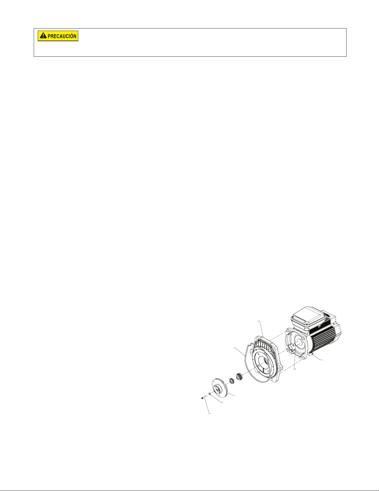
18
NO haga funcionar la bomba en seco. Si hace funcionar la bomba en seco, el sello mecánico se dañará y la bomba comenzará a perder. Si esto
ocurre, deberá cambiar el sello dañado. SIEMPRE mantenga el nivel de agua adecuado. Si el nivel de agua cae por debajo del puerto de succión,
la bomba extraerá aire del puerto de succión, perderá cebado y funcionará en seco, lo que dañará el sello. El funcionamiento continuo en este estado puede causar una
pérdida de presión, lo que dañará la caja de la bomba, el propulsor y sello y puede provocar la pérdida de propiedad y lesiones personales.
Armar la bomba de nuevo
1. Cuando este instalando el sello mecánico de
la flecha, use un sellador de silicón en la parte
metálica de la flecha antes de presionar contra
la placa de sello, y teniendo mucho cuidado de
mantener el sellador de silicón alejado del la cara
de sellado de la bomba. Asegúrese que el sello se
encuentre completamente asentado y deje pasar
24 horas para permitir que el sellador seque. (Kid
de remplazo completo con la placa de sello y el sello
mecánico esta disponible, P/N 350201/350101.)
2. Antes de instalar la sección cerámica del sello en
el impulsor, asegúrese que el impulsor está limpio.
Use un jabón de poca densidad y agua para sellar
el sello. Empuje el sello en el impulsor con los
dedos gordos y pase un paño para limpiar las
caras cerámicas y de carbón.
3. Reinstalar de nuevo la placa de sello al motor.
Ajustando los Pernos, 3/8-16 x 7/8 (2,22 cm)
de cabeza hexagonal, a un torque de 7,91 Nm
de manera cruzada (apretar uno de los pernos
y después apretar el perno opuesto y repita la
misma secuencia hasta que todos los pernos estén
ajustados al torque requerido).
4. Limpie la rosca de la flecha y la rosca del impulsor,
después enrosque el impulsor a la flecha del motor.
5. Atornille el tornillo de cierre del impulsor (en
el sentido opuesto de las agujas del reloj para
apretar).
6. Monte de nuevo el difusor en la placa de sello.
Instrucciones para encender de nuevo
Si se instala la bomba debajo del nivel de agua en la
piscina, cierre las líneas de regreso y de aspiración antes
de abrir la olla de pelo y pelusa en la bomba. Asegúrese
de abrir de nuevo las válvulas antes de usar.
Imprimar la bomba
La olla de colador de bomba tiene que llenarse con agua
antes de que se empiece la bomba incialmente. Siga
estos pasos para imprimar la bomba.
1. Quite la abrazadera plástica de la tapa de la bomba.
Quite la tapa de la bomba.
2. Llene la olla de colador de bomba con agua.
3. Arme de nuevo el cubierto de bomba y abrazadera
plástica en la olla de colador. Ahora la bomba está
lista para imprimar.
4. Abra válvula de escape de aire en el filtro y
manténgase a distancia del filtro.
5. Encienda el interruptor o reloj.
6. Cuando agua sale de la válvula de escape de aire,
cierre la válvula. Este sistema ahora debe estar
libre de aire y circulando agua de nuevo a la piscina
y de vuelta.
7. Para bomba de 2 velocidades:
• La bomba debe funcionar en alta velocidad
para imprimar.
• La bomba no debe funcionar por más de 8
minutos antes de que se logre imprimar.
Asegúrese que las clavijas plásticas y las
inserciones de tornillos de mantener están alineado.
7. Engrase el anillo en O del difusor y empaque de
PLACA DEL SELLO
placa de sello o el anillo en O antes de armar de
nuevo.
8. Engrase las roscas de perno, arme el montaje de
abajo del motor al cuerpo de olla de colar y bomba al
BRIDA DE PLACA
DE SELLO
usar los dos pernos que corren a través para tener
alineamiento adecuado. Colocar los Pernos, 3/8
-16 x 2 de cabeza hexagonal 18-8 acero inoxidable
(se requieren 2) a través de la placa de sellado y
la voluta y no los ajuste hasta que los Pernos de
3/8, 16 x 1-1/4 (3,18 cm) cabeza hexagonal 18-8
acero inoxidable (se requieren 4) estén ajustados
a mano. Ajustar todos los pernos a un torque de
12,43 Nm, de manera cruzada.
SELLO DE TORNILLO
DE FIJACIÓN
TORNILLO DE FIJACIÓN
9. Llene la bomba con agua.
10. Instale de nuevo la tapa de bomba y abrazadera
plástica; vea INSTRUCCIONES PARA ENCENDER
DE NUEVO.
11. Prepare de nuevo el sistema.
Guía de instalatión y del usuario de la bomba de alto rendimiento WHISPERFLO
PROPULSOR
®
PERNO
EJE DE MOTOR
Page 23
LOCALIZADOR DE AVERÍAS
Problema Posible causa Medida correctiva
19
Si la bomba falla.
Capacidad reducida y/o
presión baja de agua.
La bomba no imprima – demasiado aire.
La bomba no imprima—no hay agua suficiente
El colador de bomba está atascado
Empaque de colador de bomba defectuoso.
Bolsas de aire o fugas en la línea de aspiración.
Impulsor atascado.
Colador de bomba atascado.
Revise la tubería de succión y las prensastopas en cualquier
válvulas de puerta de aspiración. Cierre la tapa en la olla de
coladora de bomba y asegúrese que el empaque de tapa
está en lugar.Revise el nivel de agua para asegurarse que la
desnatadora no está jalando aire.
Asegúrese que las líneas de aspiración, el colador de bomba,
y la voluta de bomba están llenas con agua.
Asegúrese que la válvula en la línea de aspiración está
funcionando y abierta, (algunos sistemas no tienen válvulas).
Revise el nivel de agua para asegurarse que hay agua disponible
a través de la desnatadora.
Limpie la olla de coladora de bomba.
Reemplazar empaque.
ESPAÑOL
Revise la tubería de succión y las prensastopas en cualquier
válvulas de puerta de aspiración. Cierre la tapa en la olla de
coladora de bomba y asegúrese que el empaque de tapa
está en lugar.Revise el nivel de agua para asegurarse que la
desnatadora no está jalando aire.
Apague la energía eléctrica en los interruptores de circuito
de la bomba.
Desensamblar (Referir a Desensamblaje de la bomba, página
16).
Remover la basura del impulsor, si la basura no pueden ser
removida por complete, siga las siguientes instrucciones:
1. Remueva el Tornillo de 1/4, 20x1, LH, Phillips MS 18-8 de
acero inoxidable y la arandela de goma del impulsor.
2. Remueva el impulsor, termine de limpiarlo y vuelva a
instalar.
Reensamblar (Referir a Armar la bomba de nuevo, página 17).
Limpie el depósito de aspiración.
Guía de instalatión y del usuario de la bomba de alto rendimiento WHISPERFLO
®
Page 24
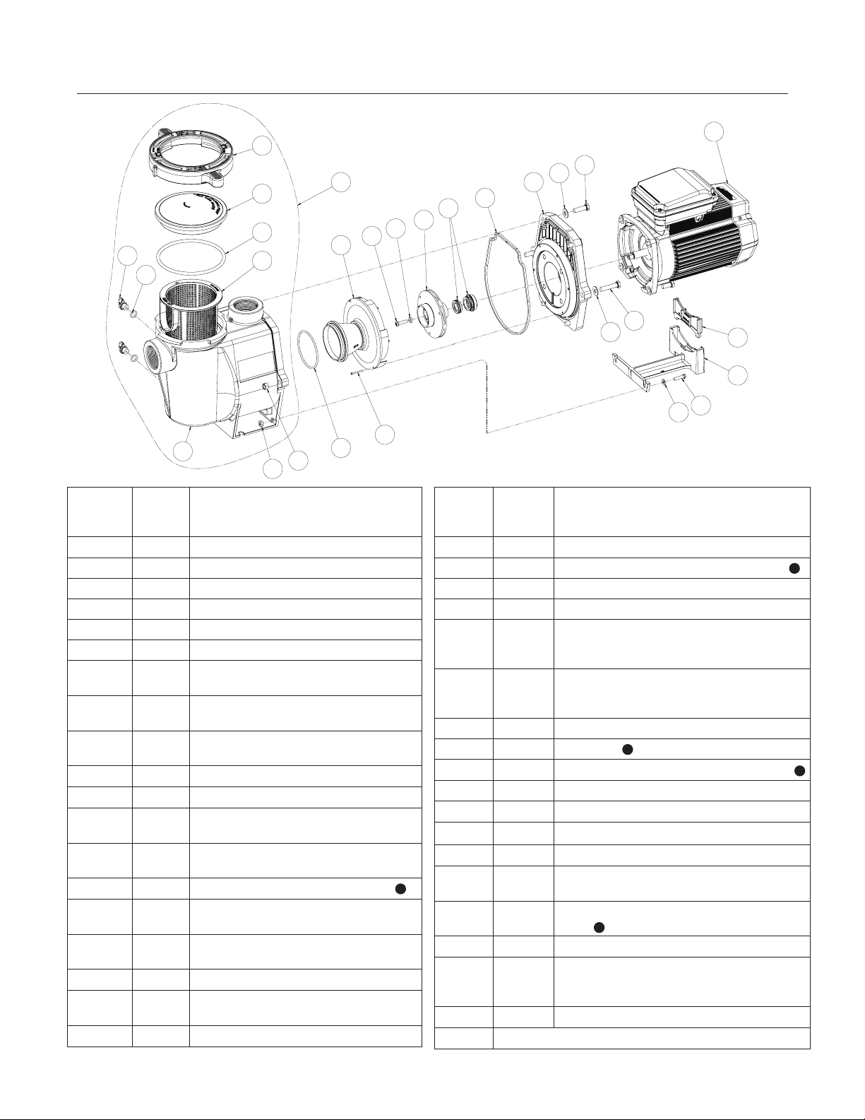
20
PIEZAS DE REEMPLAZO
1
2
3
24
25
10
4
22
13
11
8
Número
de
P/N Descripción
artículo
1 357199 Abrazadera, Cam & Ramp, Almendra
1 357150 Abrazadera, Cam & Ramp, Negro
2 357151 Tapa, transparente, bomba WFE
2 357156 Tapa, resistente química, Cam & Ramp
3 350013 Tapa WFE Anillo en O
4 070387 Canastilla del filtro, WFE
5 070430
6 072184
7 070431
Perno, 3/8 - 16 x 1,25, cabeza hexagonal
acero inox, 4 Req.
Arandelas, 3/8 x 13/16 O.D. acero inox,
6 Req.
Perno, 3/8 - 16 x 1,75, cabeza hexagonal
acero inox, 2 Req.
8 071403 Tuerca, 3/8, 16 hex hd., 2 req.
9 357100 Placa de sello de Empaque, Negro
10 357149
10 350015
Voluta & placa de sello, Almendra
Kit de reemplazo
Voluta & Olla de Bomba WFE,
Almendra
10 357157 Voluta & Olla de Bomba WFE, Negro
11 355227
12 071660
Anillo en O Parker de Bomba WFE,
#2-238
Tornillo de Tope, #4-40 X 1-1/8 SFE,
2 req.
13 072928 Montaje de Difusor, WFE- 12, Sólo 3 HP
13 072927
Montaje de Difusor, WFE- 2-8,
.5 HP–2.5 HP
14 071652 Tornillo de Tope, 1/4, 20 x 1 lh. Phillips
27
5
6
1826
9
1616
28
15
14
7
6
23
12
20
19
21
Número
de
P/N Descripción
artículo
15 075713 Arandela de Hule de Bomba WFE
16 071734S Sello PA-7 con Asiento Ceramico, PS1000
1
16 071728 Sello A7 con Asiento Ceramico, PS201
17 070429 Perno, 3/8, 16 x 7/8 s/s hex hd., 4 req.
Placa de Sello Juego WFE, Almendra
18 350201
(Incluye sello mecánico instalado)
# 9, 16 & 18
Placa de Sello Juego WFE, Negro
18 350101
(Incluye sello mecánico instalado)
# 16 & 18
19 070927 Pie WFE - Bomba 4, Almendra
19 357159 Pie, Negro
20 070929 Inserción de Pie de Bomba WFE, Almendra
1
1
20 357160 Inserción de Pie de Bomba WFE, Negro
21 071657
Tornillo, 1/4, 20 x 1 pulg. hex hd. s/s, 2 req.
22 071406 Tuerca, 1/4, 20 hex. hd. s/s, 2 req.
23 072183 Tuerca, 1/4, 20 hex. hd. s/s, 2 req.
1
24 071131
24 357161
Tapón con Perilla para Desagüe, Almendra
2 req.
Tapón con Perilla para Desagüe, Negro
2 req.
1
25 192115 Tapón de Desagüe de O-anillo, 2 req.
Juego para Reemplazar Voluta/Placa de
26 357149
Sello, Almendra (Incluye #1-4, 9, 10, 16, 18,
24, and 25)
- 357923Z Kit protector de ventilador, TEFC/Súper deber
27 Página siguiente
Guía de instalatión y del usuario de la bomba de alto rendimiento WHISPERFLO
®
Page 25
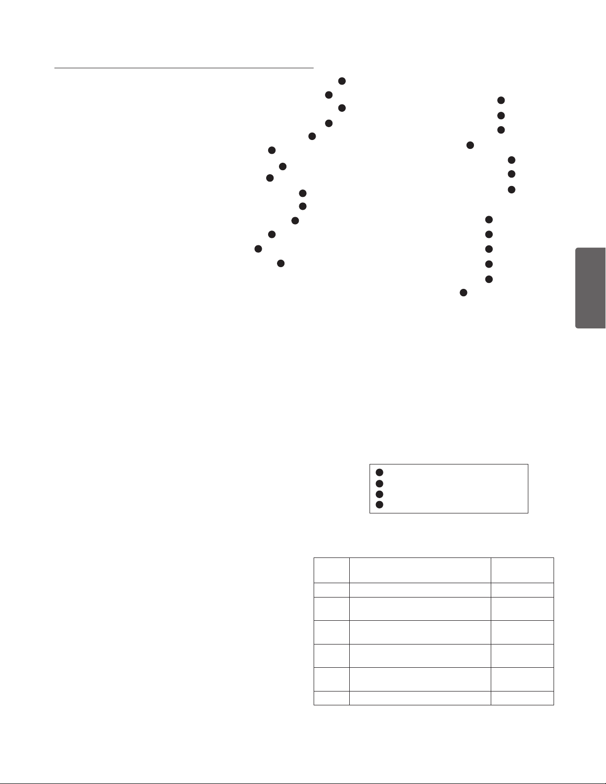
Número
artículo
de
Núm. de
pieza
Descripción
Motores
27 355008S 3/4 HP, 60 Hz, WFE-2, 3 & 24, 1 spd., Almendra, 31 lbs.
27 355010S 1 HP, 60 Hz, WFE-4 & 26, 1 spd., Almendra,, 33 lbs.
27 355012S 1-1/2 HP, 60 Hz, WFE-6 & 28, 1 spd., Almendra,, 39 lbs.
27 355014S 2 HP, 60 Hz, WFE-8 & 30, 1 spd., Almendra,, 40 lbs.
27 355016S 3 HP, 60 Hz, WFE-12, 1 spd., Almendra, 40 lbs.
27 356630S 1 HP, WFDS-4 & 26, 2 spd., 34 lbs.
27 071320S 1-1/2 HP, WFDS-6 & 28, 2 spd., 36 lbs.
27 071321S 2 HP, WFDS-8 & 30, 2 spd., 45 lbs.
27 355018S 1/2 HP, WF-2 & 23, 1 spd., Almendra, 39 lbs.
27 355020S 3/4 HP, WF-3 & 24, 1 spd., Almendra, 26 lbs.
27 355022S 1 HP, WF-4 & 26, 1 spd., Almendra, 28 lbs.
27 355024S 1-1/2 HP, WF-6 & 28, 1 spd., 39 lbs.
27 355026S 2 HP, WF-8 & 30, 1 spd., 32 lbs.
27 355033S 3 HP, WF-12, 1 spd., Almendra, 40 lbs.
4
4
4
3
3
3
3
3
3
27 355203S 1 HP, WFK-4, 3 ph, 1 spd., Negro, 28 lbs.
27 355204S 1-1/2 HP, WFK-6, 3 ph, 1 spd., Negro, 30 lbs.
27 355205S 2 HP, WFK-8, 3 ph, 1 spd., Negro, 37 lbs.
27 355398S 3 HP, WFK-12, 3 ph, 1 spd., Negro, 35 lbs.
27 356626S 1 HP, WFK-4, 3 ph, 1 spd., Almendra, 28lbs.
27 356627S 1-1/2 HP, WFK-6, 3 ph, 1 spd., Almendra, 30lbs.
27 356628S 2 HP, WFK-8, 3 ph, 1 spd., Almendra, 37 lbs.
27 356629S 3 HP, WFK-12, 3 ph, 1 spd., Almendra, 35 lbs.
27
354805S
1 HP, WFK-4, Súper deber, 3 ph, 1 spd., Almendra,
28lbs.
27
354807S
1-1/2 HP, WFK-6, Súper deber, 3 ph., 1 spd., Almendra,
30lbs.
27
354809S
2 HP, WFK-8, Súper deber, 3 ph., 1 spd., Almendra,
36 lbs.
27
354811S
3 HP, WFK-12, Súper deber, 3 ph., 1 spd., Almendra,
39 lbs.
27
27
27
27
354821S
354823S
354815S
354817S
1 HP, WFET-4, TEFC, 1 ph., 1 spd., Almendra, 29 lbs.
1-1/2 HP, WFET-6, TEFC, 1 ph., 1 spd., Almendra, 31lbs.
2 HP, WFET-8, TEFC, 1 ph., 1 spd., Almendra, 37lbs.
3 HP, WFET-12, TEFC, 1 ph., 1 spd., Almendra, 41lbs.
21
Fondo Potencia Submontaje.
Incluye Artículos: 12-18, 27-28
2
2
2
2
2
075136 WFE-2
075137 WFE-3, WFE-24
075138 WFE-4, WFE-26
075139 WFE-6, WFE-28
075140
075141 WFE-12
WFE-8, WFE-30
2
075145 WFDS-3, WFDS-24
075142 WFDS-4, WFDS-26
075143 WFDS-6, WFDS-28
2
2
2
4
4
4
075144 WFDS-8, WFDS-30
075251 WF-2, WF-23
075252 WF-3, WF-24
075253 WF-4, WF-26
075254 WF-6,WF-28
075255 WF-8,WF-30
075256 WF-12
3
3
3
3
3
3
Fondo Líquido - Todas las Partes
sin el Motor
075451 WFE-2 fluid end, 1/2 HP
075452 WFE-3 fluid end, 3/4 HP
075453 WFE-4 fluid end, 1 HP
075454 WFE-6 fluid end, 1-1/2 HP
075455 WFE-8 fluid end, 2 HP
075456 WFE-12 fluid end, 3 HP
1
CSA/CUL (sólo) para Canadá.
2
Energía eficiente, sola fase.
3
Eficiencia Estánder, sola fase.
4
Dos velocidad, sola fase.
ESPAÑOL
No Mostrado
79129900 2-Velocidad Toggle Interruptor
350202 Placa de Sello Juego: Placa de Sello (Almendra),
Empaque (Negro), con instalado Sello (Incluye
Artículos: 9, 16, & 18)
350203 Placa de Sello Juego: Placa de Sello (Negro),
Empaque (Negro), con instalado Sello (Incluye
Artículos: 9, 16, & 18)
357243 Olla la Asamblea, Almendra NPT. (Incluye
Artículos: 1-4, 10, 24 [qty. 2], 25 [qty. 2])
357244 Olla la Asamblea, Negro NPT. (Incluye Artículos:
1-4, 10, 24 [qty. 2], 25 [qty. 2])
Guía de instalatión y del usuario de la bomba de alto rendimiento WHISPERFLO
Tabla de impulsor
HP TAMAÑO
1/2 WFE-2, WF-2, WF-23, WFK-2 073126
3/4
1
1½
2
3 WFE-12, WFET-12, WF-12, WFK-12 073131
WFE-3, WFE-24, WF-3, WF-24,
WFK-3, WFDS-24
WFE-4, WFE-26, WFET-4, WF-4, WF-
26, WFK-4, WFDS-4, WFDS-26
WFE-6, WFE-28, WFET-6, WF-6, WF-
28, WFK-6, WFDS-6, WFDS-28
WFE-8, WFE-30, WFET-8, WF-8, WF-
30, WFK-8, WFDS-8, WFDS-30
PIEZA STD.
NO. DE
073127
073128
073129
073130
®
Page 26
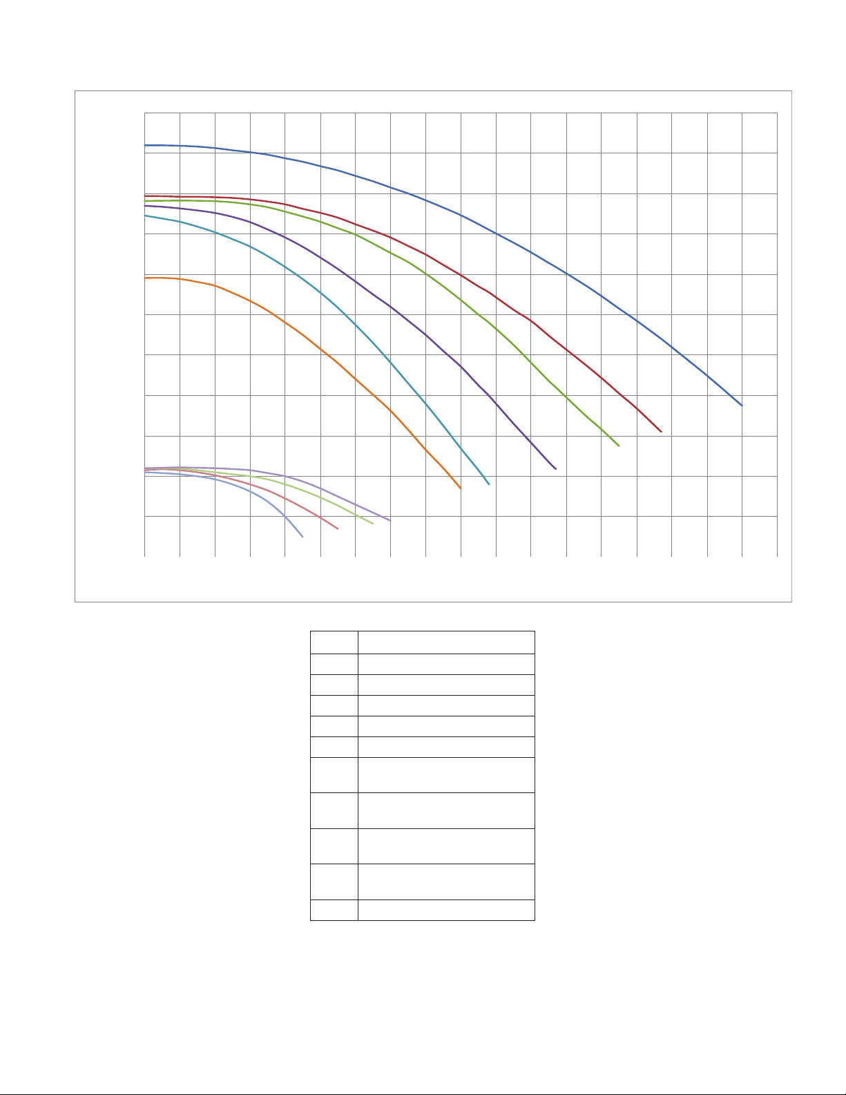
22
0
10
20
30
40
50
60
70
80
90
100
110
0102030405060708090100 11 0120 13 0140 150160 170180
TOTA L DYNAMIC HEAD IN FT OF WATER
GALONES POR MINUTO
E
F
G
H
I
J
D
C
B
A
CARGA TOTAL EN PIES DE AQUA
Curvas de rendimiento de la bomba
Curva Modelo
A WFDS-3, WFDS-24
B WFDS-4, WFDS-26
C WFDS-6, WFDS-28
D WFDS-8, WFDS-30
E WFE-2, WF-2, WF-23, WFK-2
F WFE-3, WFE-24, WF-3, WF-24,
WFK-3, WFDS-3, WFDS-24
G WFE-4, WFE-26, WFET-4, WF-4,
WF-26, WFK-4, WFDS-4, WFDS-26
H WFE-6, WFE-28, WFET-6, WF-6,
WF-28, WFK-6, WFDS-6, WFDS-28
I WFE-8, WFE-30, WFET-8, WF-8,
WF-30, WFK-8, WFDS-8, WFDS-30
J WFE-12, WFET-12, WF-12, WFK-12
Page 27

NOTES127$6
Page 28

1620 HAWKINS AVE., SANFORD, NC 27330 • (919) 566-8000
*071109*
10951 WEST LOS ANGELES AVE., MOORPARK, CA 93021 • (805) 553-5000
WWW.PENTAIRPOOL.COM
© 2018 Pentair Water Pool and Spa, Inc. All rights reserved. This document is subject to change without notice.
Todos los derechos reservados. Este documento está sujeto a cambios sin previo aviso.
P/N 071109 REV. L 7/17/18
 Loading...