

Pentair WATERFALL AFP-75, WATERFALL AFP-150, WATERFALL AF-120, WATERFALL AF-75, WATERFALL AFP-120 Installation And User Manual
Page 1
ENGLISH
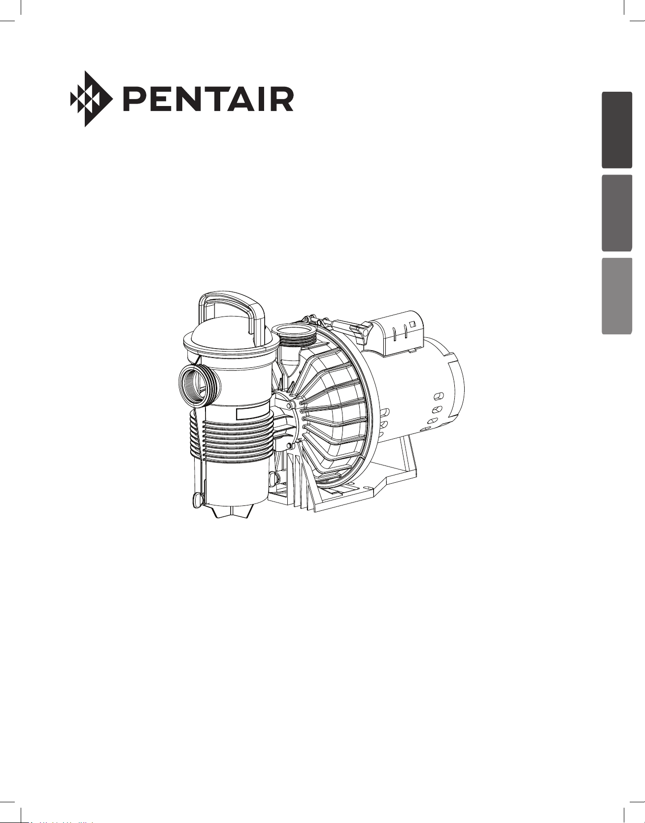
WATERFALL™
SPECIALTY PUMP
ESPAÑOL
FRANÇAIS
INSTALLATION AND
USER’S GUIDE
IMPORTANT SAFETY INSTRUCTIONS
READ AND FOLLOW ALL INSTRUCTIONS
SAVE THESE INSTRUCTIONS
Page 2

WATERFALL™ Specialty Pump Installation and User’s Guide
i
CUSTOMER SERVICE / TECHNICAL SUPPORT
If you have questions about ordering Pentair replacement parts, and pool products, please contact:
Customer Service and Technical Support, USA
(8 A.M. to 7:30 P.M. — Eastern Time)
Phone: (800) 831-7133
Fax: (800) 284-4151
Web site
Visit www.pentair.com for more information about
Pentair pool products.
TABLE OF CONTENTS
Important Pump Warning and
Safety Instructions ...............................................
Introduction ..........................................................
Pump Overview
Pump Strainer Basket
Installation ............................................................
Location
Selection of Pump and Piping
Piping, Fitting and Valve Installation
Electrical Installation
Wiring
Grounding
Bonding
Operating the Pump .............................................
Initial Start-Up
Maintenance .........................................................
Cleaning the Strainer Basket
Winterizing
Motor Care
Sanford, North Carolina (8 A.M. to 4:30 P.M. ET)
Phone: (919) 566-8000
Fax: (919) 566-8920
Moorpark, California (8 A.M. to 4:30 P.M. PT)
Phone: (805) 553-5000 (Ext. 5591)
Fax: (805) 553-5515
Servicing .............................................................
ii
1
1
1
2
2
2
3
4
4
4
4
5
5
6
6
7
7
Pump Disassembly
Shaft Seal Replacement
Pump Reassembly
Restart Instructions ...........................................
Priming the Pump
Troubleshooting .................................................
Replacement Parts .............................................
8
8
9
10
11
11
12
13
P/N 355143 Rev. D 5/17/19
Page 3
WATERFALL™ Specialty Pump Installation and User’s Guide
ENGLISH
IMPORTANT PUMP WARNING AND SAFETY INSTRUCTIONS
F
IMPORTANT NOTICE
This guide provides installation and operation instructions for this pump.
Consult Pentair with any questions regarding this equipment.
Attention Installer: This guide contains important information about the
installation, operation and safe use of this product. This information should
be given to the owner and/or operator of this equipment after installation
or left on or near the pump.
Attention User: This manual contains important information that will help
you in operating and maintaining this product. Please retain it for future
reference.
READ AND FOLLOW ALL INSTRUCTIONS
SAVE THESE INSTRUCTIONS
This is the safety alert symbol. When you see this
symbol on your system or in this manual, look for
one of the following signal words and be alert to
the potential for personal injury.
Warns about hazards that can cause death,
serious personal injury, or major property damage
if ignored.
Warns about hazards that may cause death,
serious personal injury, or major property damage
if ignored.
Warns about hazards that may or can cause minor
personal injury or property damage
if ignored.
NOTE Indicates special instructions not related to
hazards.
Carefully read and follow all safety instructions in this manual and on
equipment. Keep safety labels in good condition; replace if missing
or damaged.
When installing and using this electrical equipment, basic safety
precautions should always be followed, include the following:
Do not permit children to use this product.
RISK OF ELECTRICAL SHOCK. Connect only to
a branch circuit protected by a ground-fault circuitinterrupter (GFCI). Contact a qualified electrician if you cannot verify that
the circuit is protected by a GFCI.
This unit must be connected only to a supply circuit
that is protected by a ground-fault circuit-interrupter
(GFCI). Such a GFCI should be provided by the installer and should
be tested on a routine basis. To test the GFCI, push the test button.
The GFCI should interrupt power. Push the reset button. Power should
be restored. If the GFCI fails to operate in this manner, the GFCI is
defective. If the GFCI interrupts power to the pump without the test button
being pushed, a ground current is flowing, indicating the possibility of an
electric shock. Do not use this pump. Disconnect the pump and have the
problem corrected by a qualified service representative before using.
This pump is for use with permanent swimming
pools and may also be used with hot tubs and spas
if so marked. Do not use with storable pools. A permanently-installed pool
is constructed in or on the ground or in a building such that it cannot be
readily disassembled for storage. A storable pool is constructed so that
it is capable of being readily disassembled for storage and reassembled
to its original integrity.
ii
General Warnings
• Never open the inside of the drive motor enclosure. There is a
capacitor bank that holds a 230 VAC charge even when there is no
power to the unit.
• The pump is not submersible.
• The pump is capable of high flow rates; use caution when installing
and programming to limit pumps performance potential with old or
questionable equipment.
• Code requirements for electrical connection differ from country to
country, state to state, as well as local municipalities. Install equipment
in accordance with the National Electrical Code and all applicable
local codes and ordinances.
• Before servicing the pump; switch OFF power to the pump by
disconnecting the main circuit to the pump.
• This appliance is not intended for use by persons (including children) of
reduced physical, sensory or mental capabilities, or lack of experience
and knowledge, unless they have been given supervision or instruction
concerning the use of the appliance by a person responsible for their
safety.
FAILURE TO FOLLOW ALL INSTRUCTIONS AND
WARNINGS CAN RESULT IN SERIOUS BODILY
INJURY OR DEATH. THIS PUMP SHOULD BE INSTALLED AND
SERVICED ONLY BY A QUALIFIED POOL SERVICE PROFESSIONAL.
INSTALLERS, POOL OPERATORS AND OWNERS MUST READ
THESE WARNINGS AND ALL INSTRUCTIONS IN THE OWNER’S
MANUAL BEFORE USING THIS PUMP. THESE WARNINGS AND
THE OWNER’S MANUAL MUST BE LEFT WITH THE POOL OWNER.
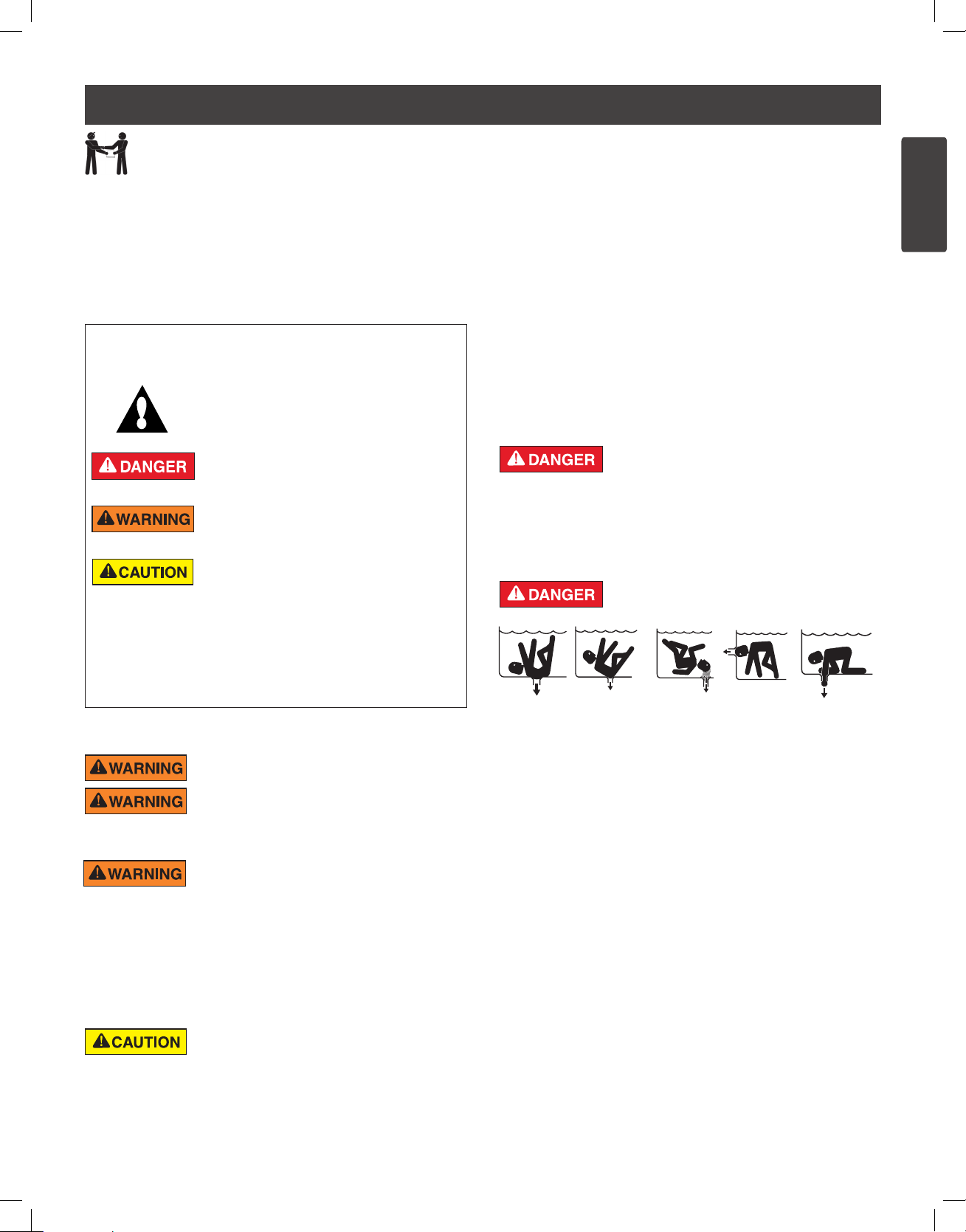
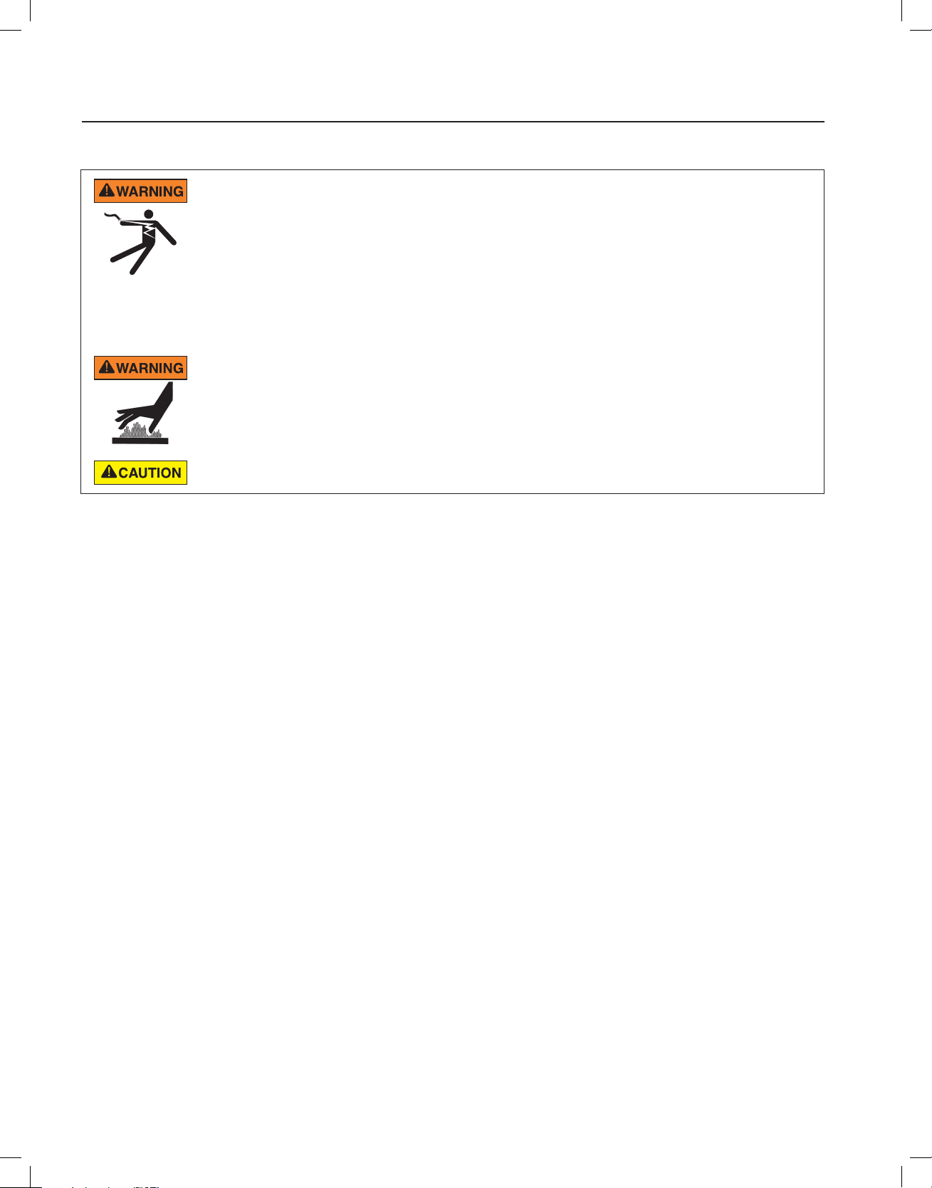
SUCTION ENTRAPMENT HAZARD: STAY OFF
THE MAIN DRAIN AND AWAY FROM ALL SUCTION
OUTLETS!
THIS PUMP PRODUCES HIGH LEVELS OF SUCTION AND CREATES
A STRONG VACUUM AT THE MAIN DRAIN AT THE BOTTOM OF THE
BODY OF WATER. THIS SUCTION IS SO STRONG THAT IT CAN TRAP
ADULTS OR CHILDREN UNDER WATER IF THEY COME IN CLOSE
PROXIMITY TO A DRAIN OR A LOOSE OR BROKEN DRAIN COVER
OR GRATE.
THE USE OF UNAPPROVED COVERS OR ALLOWING USE OF
THE POOL OR SPA WHEN COVERS ARE MISSING, CRACKED OR
BROKEN CAN RESULT IN BODY OR LIMB ENTRAPMENT, HAIR
ENTANGLEMENT, BODY ENTRAPMENT, EVISCERATION AND/OR
DEATH.
The suction at a drain or outlet can cause:
Limb Entrapment: When a limb is sucked or inserted into an opening
resulting in a mechanical bind or swelling. This hazard is present when
a drain cover is missing, broken, loose, cracked or not properly secured.
Hair Entanglement: When the hair tangles or knots in the drain cover,
trapping the swimmer underwater. This hazard is present when the flow
rating of the cover is too small for the pump or pumps.
Body Entrapment: When a portion of the body is held against the drain
cover trapping the swimmer underwater. This hazard is present when the
drain cover is missing, broken or the cover flow rating is not high enough
for the pump or pumps.
Evisceration/Disembowelment: When a person sits on an open pool
(particularly a child wading pool) or spa outlet and suction is applied directly
to the intestines, causing severe intestinal damage. This hazard is present
when the drain cover is missing, loose, cracked, or not properly secured.
Page 4
WATERFALL™ Specialty Pump Installation and User’s Guide
iii
IMPORTANT PUMP WARNING AND SAFETY INSTRUCTIONS
Mechanical Entrapment: When jewelry, swimsuit, hair decorations, finger,
toe or knuckle is caught in an opening of an outlet or drain cover. This
hazard is present when the drain cover is missing, broken, loose, cracked,
or not properly secured.
NOTE: ALL SUCTION PLUMBING MUST BE INSTALLED IN
ACCORDANCE WITH THE LATEST NATIONAL AND LOCAL CODES,
STANDARDS AND GUIDELINES.
TO MINIMIZE THE RISK OF INJURY DUE TO
SUCTION ENTRAPMENT HAZARD:
• A properly installed and secured ANSI/ASME A112.19.8 approved
anti-entrapment suction cover must be used for each drain.
• Each suction cover must be installed at least three (3’) feet apart, as
measured from the nearest point to nearest point.
• Regularly inspect all covers for cracks, damage and advanced
weathering.
• If a cover becomes loose, cracked, damaged, broken or is missing,
replace with an appropriate certified cover.
• Replace drain covers as necessary. Drain covers deteriorate over
time due to exposure to sunlight and weather.
• Avoid getting hair, limbs or body in close proximity to any suction
cover, pool drain or outlet.
• Disable suction outlets or reconfigure into return inlets.
A clearly labeled emergency shut-off switch for the
pump must be in an easily accessible, obvious place.
Make sure users know where it is and how to use it in case of emergency.
The Virginia Graeme Baker (VGB) Pool and Spa Safety Act creates
new requirements for owners and operators of commercial swimming
pools and spas.
Commercial pools or spas constructed on or after December 19, 2008,
shall utilize:
(A) A multiple main drain system without isolation capability with suction
outlet covers that meet ASME/ANSI A112.19.8a Suction Fittings for
Use in Swimming Pools, Wading Pools, Spas, and Hot Tubs and either:
(i) A safety vacuum release system (SVRS) meeting ASME/ANSI
A112.19.17 Manufactured Safety Vacuum Release systems (SVRS)
for Residential and Commercial Swimming Pool, Spa, Hot Tub,
and Wading Pool Suction Systems and/or ASTM F2387 Standard
Specification for Manufactured Safety Vacuum Release Systems
(SVRS) for Swimming pools, Spas and Hot Tubs or
(ii) A properly designed and tested suction-limiting vent system or
(iii) An automatic pump shut-off system.
Commercial pools and spas constructed prior to December 19, 2008,
with a single submerged suction outlet shall use a suction outlet cover
that meets ASME/ANSI A112.19.8a and either:
(A) A SVRS meeting ASME/ANSI A112.19.17 and/or ASTM F2387, or
(B) A properly designed and tested suction-limiting vent system, or
(C) An automatic pump shut-off system, or
(D) Disabled submerged outlets, or
(E) Suction outlets shall be reconfigured into return inlets.
For Installation of Electrical Controls at Equipment Pad (ON/OFF
Switches, Timers and Automation Load Center)
Install all electrical controls at equipment pad, such as
on/off switches, timers, and control systems, etc. to
allow the operation (startup, shut-down, or servicing)
of any pump or filter so the user does not place any
portion of his/her body over or near the pump strainer
lid, filter lid or valve closures. This installation should
allow the user enough space to stand clear of the filter
and pump during system start-up, shut down or servicing of the system filter.
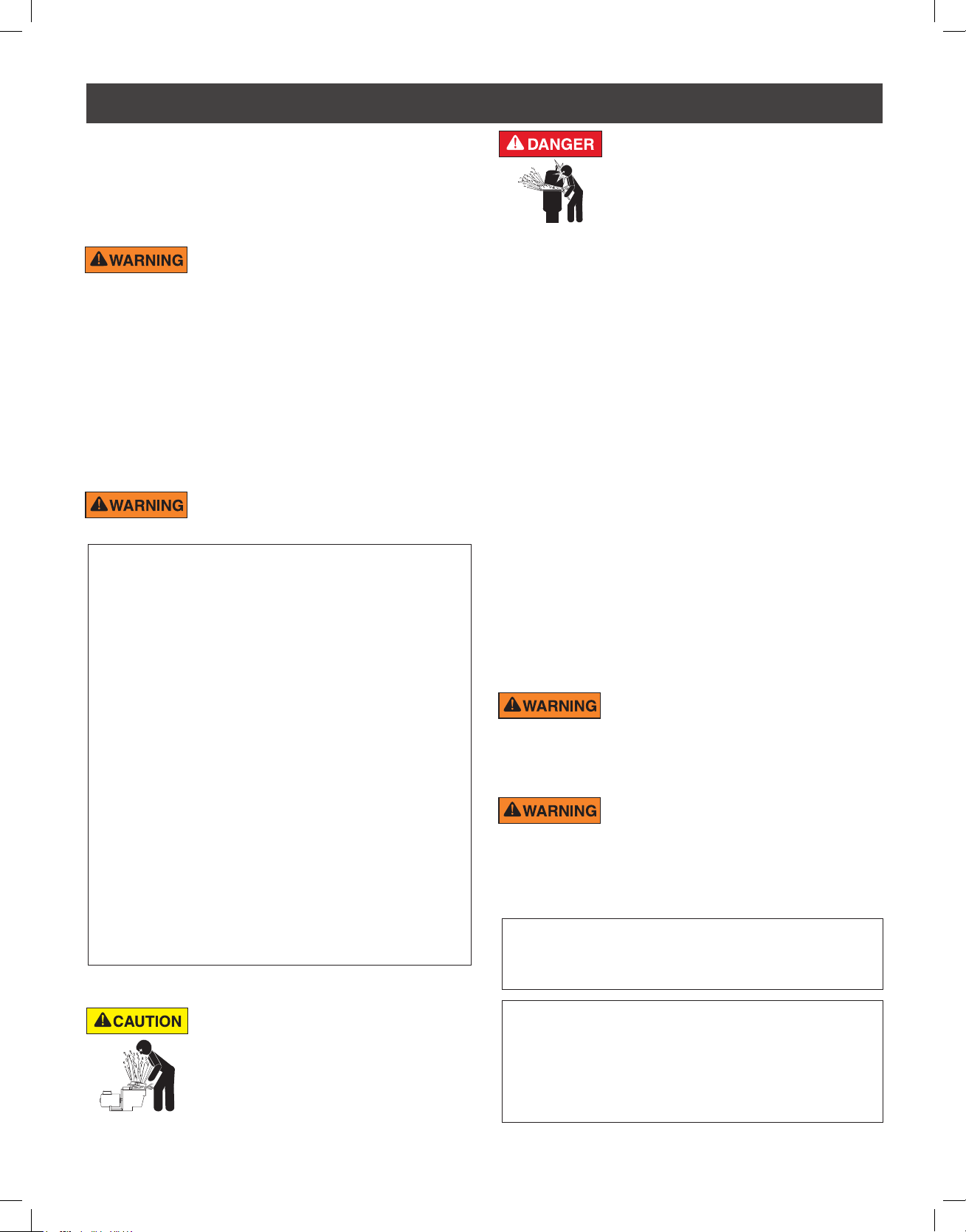
HAZARDOUS PRESSURE: STAND CLEAR OF
PUMP AND FILTER DURING START UP
Circulation systems operate under high pressure.
When any part of the circulating system (i.e.
locking ring, pump, filter, valves, etc.) is serviced,
air can enter the system and become pressurized.
Pressurized air can cause the pump housing cover, filter lid, and valves
to violently separate which can result in severe personal injury or death.
Filter tank lid and strainer cover must be properly secured to prevent
violent separation. Stand clear of all circulation system equipment when
turning on or starting up pump.
Before servicing equipment, make note of the filter pressure. Be sure
that all controls are set to ensure the system cannot inadvertently start
during service. Turn off all power to the pump. IMPORTANT: Place filter
manual air relief valve in the open position and wait for all pressure
in the system to be relieved.
Before starting the system, fully open the manual air relief valve and place
all system valves in the “open” position to allow water to flow freely from the
tank and back to the tank. Stand clear of all equipment and start the pump.
IMPORTANT: Do not close filter manual air relief valve until all
pressure has been discharged from the valve and a steady stream
of water appears. Observe filter pressure gauge and be sure it is not
higher than the pre-service condition.
General Installation Information
• All work must be performed by a qualified service professional, and
must conform to all national, state, and local codes.
• Install to provide drainage of compartment for electrical components.
• These instructions contain information for a variety of pump models
and therefore some instructions may not apply to a specific model. All
models are intended for use in swimming pool applications. The pump
will function correctly only if it is properly sized to the specific application
and properly installed.
Pumps improperly sized or installed or used in
applications other than for which the pump was
intended can result in severe personal injury or death. These risks
may include but not be limited to electric shock, fire, flooding, suction
entrapment or severe injury or property damage caused by a structural
failure of the pump or other system component.
The pump can produce high levels of suction within
the suction side of the plumbing system. These
high levels of suction can pose a risk if a person comes within the close
proximity of the suction openings. A person can be seriously injured
by this high level of vacuum or may become trapped and drown. It is
absolutely critical that the suction plumbing be installed in accordance
with the latest national and local codes for swimming pools.
Pumps and replacement motors that are single speed and
one (1) Total HP or greater cannot be sold, offered for sale, or
installed in a residential pool for filtration use in California, Title
20 CCR sections 1601-1609.
Warnings and safety instructions for Pentair Aquatic Systems pumps
and other related products are available at:
http://www.pentairpool.com/pool-owner/safety-warnings/ or call
(800) 831-7133 for additional free copies of these instructions.
Please refer to http://www.pentairpool.com/pool-owner/safety-
warnings/ for warning and safety instructions related to the this
product.
Warning Page P/N 352557 Rev. C 7/18
Page 5
WATERFALL™ Specialty Pump Installation and User’s Guide
ENGLISH
INTRODUCTION
1
Pump Overview
Typical pool pumps are designed to circulate water through relatively high loss plumbing systems that include many
plumbing restrictions (i.e. pool filter, valves, heater, small plumbing fittings, etc.) and therefore must produce a
significant amount of pressure to push the water through all the components. If installed on plumbing systems that
do not have these types of plumbing restrictions, pool pumps will often operate very noisily and sometimes cause
damage to the system via cavitation.
The Waterfall™ Specialty Pump is specifically intended for these kind of applications, where quiet and efficient delivery
of water through low-restriction plumbing systems is required. These applications often require a pump to create some
visual effect such as a waterfall, cascade or spillway, or when water must be moved a relatively short distance.
This pump is not intended to be used in typical pool filtration pump or spa applications where pressure is required. It is
also not intended for use in systems that require water to be elevated more than 5 ft. (1.5 m) above the pool reservoir.
Strainer
Basket
Waterfall Specialty Pump
Pump Strainer Basket
The strainer basket, sometimes referred to as the ‘Hair and Lint Pot’, is located in front of the pump housing. Inside the
chamber is the basket which must be kept clean of leaves and debris at all times.
Regardless of the length of time between filter cleaning, it is important to visually inspect the hair and lint pot basket at
least once a week. A dirty basket will reduce the efficiency of the filter and heater and also put an abnormal stress on
the pump motor.
Page 6
2
WATERFALL™ Specialty Pump Installation and User’s Guide
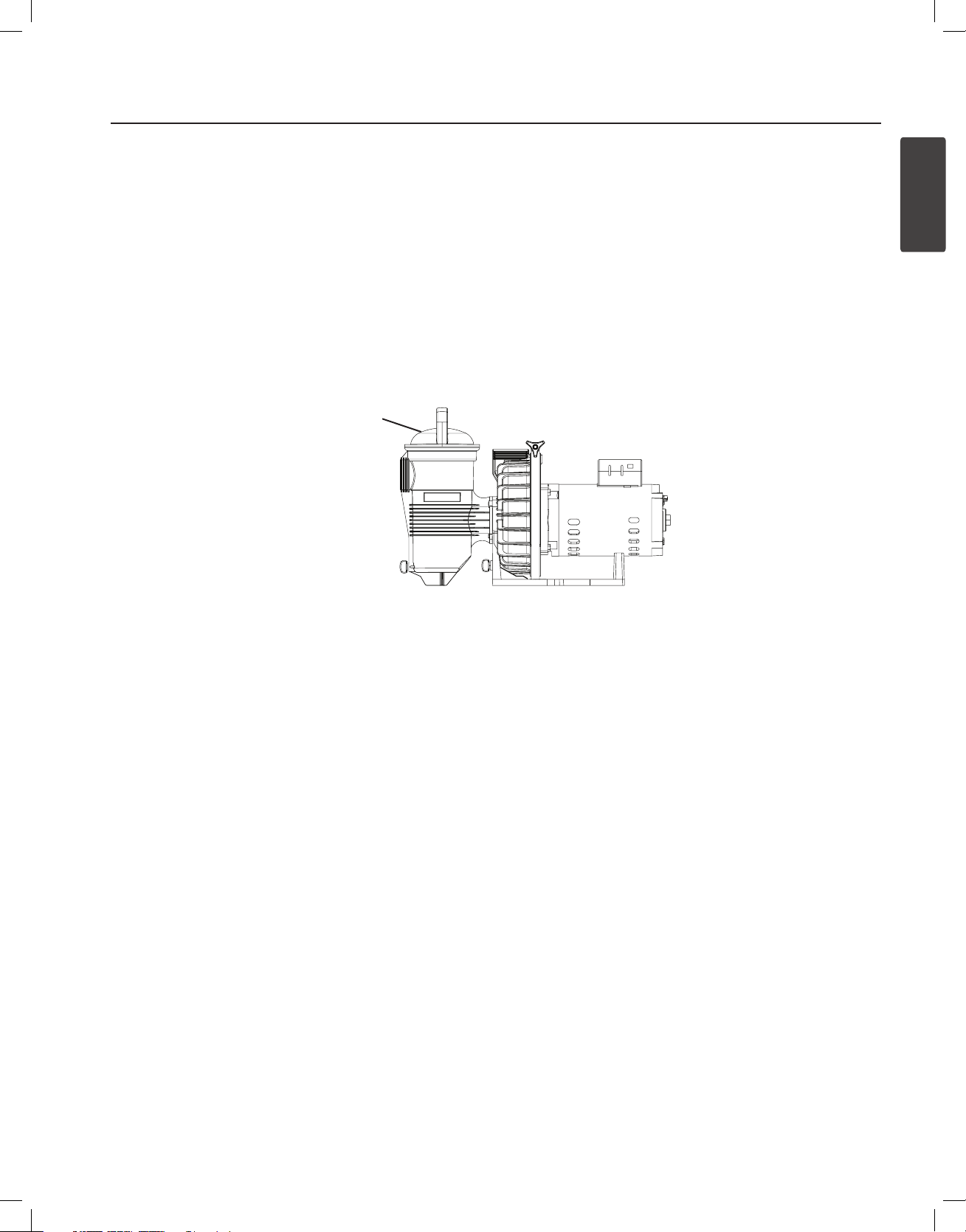
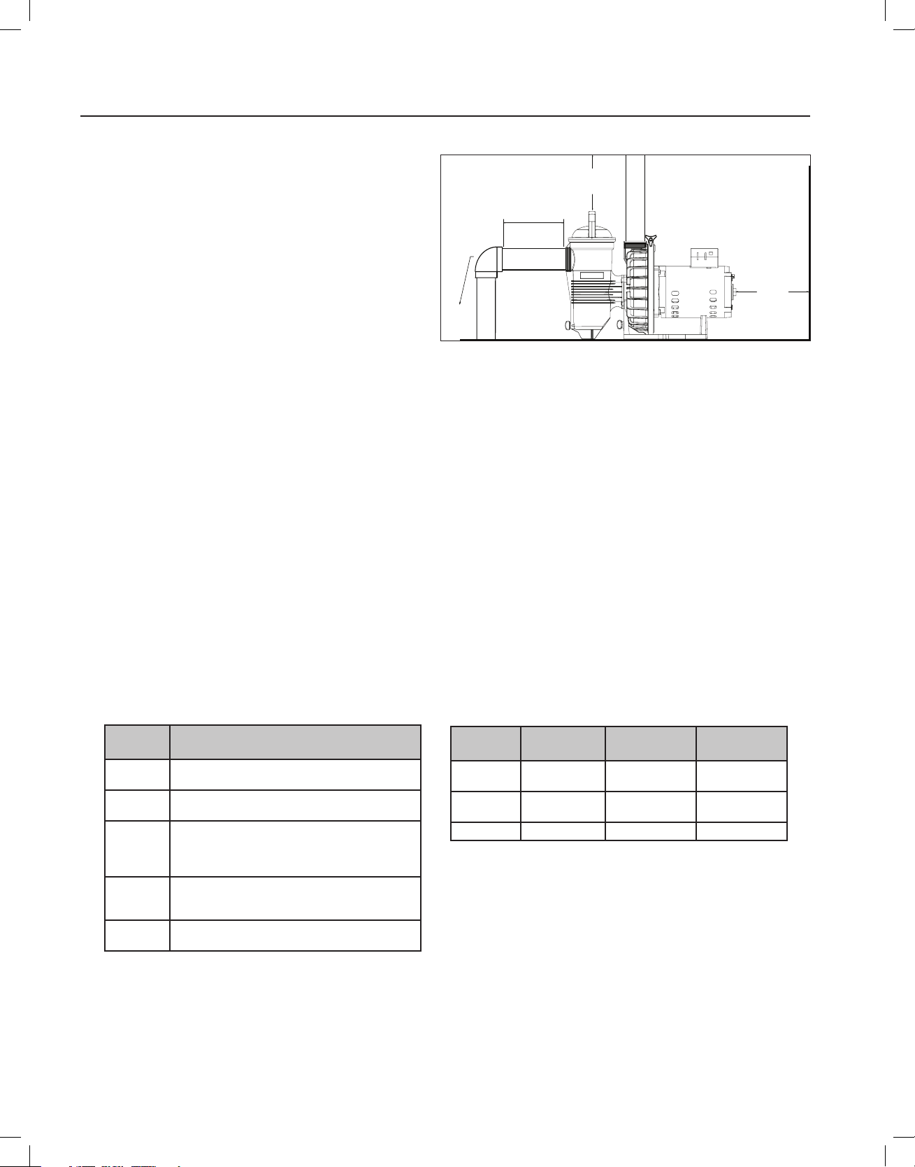
3 IN.
(7.6 CM)
MINIMUM
REAR CLEARANCE
5x SUCTION
PIPE DIAMETER
ELBOW
12 IN. (30.5 CM)
MIN. VERTICAL
CLEARANCE
INSTALLATION
Location
Be sure the Waterfall™ Specialty Pump location meets
the following requirements:
Note: Do not install this pump within an outer
enclosure or beneath the skirt of a hot tub or spa
unless marked accordingly.
1. Install the pump as close to the pool or spa as
possible. To reduce friction loss and improve
efficiency use short, direct suction piping returns.
2. Install a minimum of 5 feet (1.5 meters) from
the inside wall of the pool or spa. Canadian
installations require a minimum of 9.8 feet (3
meters) from pool water.
3. Install the pump a minimum of 3 feet (0.9 meters) from the heater outlet.
4. Do not install the pump more than 5 feet (1.5 m) above the water level.
5. Install the pump in a well ventilated location protected from excessive moisture (i.e., rain gutter downspouts,
sprinklers, etc.).
6. Install the pump with a rear clearance of at least 3 inches (7.6 cm) so that the motor can be removed easily for
maintenance and repair. A vertical clearance of 12 inches (30.5 cm) is required for strainer basket removal. See
Figure 1.
Figure 1
Selection of Pump and Piping
Many installations require that the pump elevate the water several feet to supply a waterfall or similar water feature.
This lifting requires energy and therefore reduces the amount of flow the pump can deliver. See Table 1 for estimates
on flow loss.
It is always recommended that the total system head loss be calculated and compared to the pump performance
curve before the pump and plumbing sizes are selected. However, Table 2 can be used as a quick guide to pump
selection and pipe sizing on simple installations.
Table 1: Effect of Elevation Change on Flow
Elevation
Change
Under 2’
2’ - 4’
4’ - 10’
10’ - 15’
Above 15’
Effect on Flow
Negligible reduction in flow if plumbed according to
guidelines.
Slight reduction in flow if plumbed according to
guidelines.
Flow reduced to 50-90% of maximum rating,
depending on exact elevation and system
installation. Must determine plumbing system head
loss to estimate flow.
Not usually recommended. Flow may be reduced
to 50% or less of maximum rating. This loss may be
acceptable in certain low-flow applications.
Not recommended. No flow possible above 27’ of
elevation change.
Table 2: Plumbing Size Recommendations
Pump
Model
AF-75
AFP-75
AF-120
AFP-120
AFP-150 150 GPM 2-1/2” 3”
* Maximum Rated Flow is the approximate flow the pump can discharge through a
short system of “high flow plumbing size” pipe. The pump will produce lower flow
rates if it has to raise water to a higher elevation and/or circulate water through a
long piping system.
** Minimum Plumbing Size may be used on installations where the plumbing
system is very short and direct, with few fittings or elbows. In applications, where
it is important to achieve the maximum possible flow, always use the larger “High
Flow Plumbing Size”.
Maximum*
Rated Flow
75 GPM 1-1/2” 2”
120 GPM 2” 2-1/2”
Minimum**
Plumbing Size
High Flow
Plumbing Size
Page 7

WATERFALL™ Specialty Pump Installation and User’s Guide
ENGLISH
Piping, Fitting and Valve Installation
1. Use thread seal tape or pipe sealants on all male connections of pipes and fittings. Use only pipe sealant
compounds suited for plastic pipe. DO NOT USE PETROLEUM BASED PRODUCTS.
2. Support pipe to prevent strains on the systems filter, pump and valves.
3. When connecting fitting to the pump, apply a pipe sealant to the threads and then hand tighten plus 1½ turns. DO
NOT OVERTIGHTEN.
4. Long piping runs and elbows restrict flow. For best efficiency, use the fewest possible fittings, large diameter pipe
(at least 1.5 inches) and locate equipment as close to the pool as possible. The pump suctions line should not be
smaller than the pipe size on the inlet of the pump.
5. Suction fittings must conform to ASME/ANSI A 112.19.8 M Standards. Use double suction fittings.
6. For most installations Pentair recommends installing a valve on both the pump suction and return lines so that
the pump can be isolated during routine maintenance. We also recommend a valve, elbow or tee installed in the
suction line should be no closer to the front of the pump than five (5) times the suction line pipe diameter. See
Figure 1 on previous page.
Example: A 1.5 inch pipe requires a 7.5 inch (19 cm) straight run in front of the suction inlet of the pump. This will
help the pump prime faster and last longer.
Note: DO NOT install 90° elbows directly into the pump inlet and outlet.
7. Maximum operating pressure of this pump is 50 PSI. NEVER OPERATE THIS PUMP ABOVE THIS PRESSURE.
8. This pump is NOT intended to be operated in series with other pumps.
3
Page 8
4
WATERFALL™ Specialty Pump Installation and User’s Guide
Electrical Installation
RISK OF ELECTRICAL SHOCK OR ELECTROCUTION. This pump must be installed by a licensed or certified electrician or a
qualified service professional in accordance with the National Electrical Code (NEC) and all other applicable national or local codes
and ordinances. Improper installation will create an electrical hazard which could result in death or serious injury to users, installers, or
others due to electrical shock, and may also cause damage to property.
Always disconnect power to the pump at the circuit breaker before servicing the pump. Failure to do so could result in death
or serious injury to service people, users or others due to electric shock.
Read all servicing instructions before working on the pump.
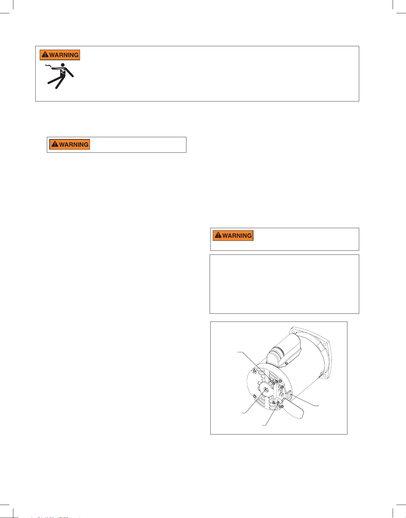
Wiring
1. Be sure all electrical breakers, switches and automatic
controls are turned off before wiring motor.
STORED CHARGE - Wait at least sixty
(60) seconds before servicing.
2. Become familiar with the wiring diagram, volts, hertz,
amps and phase of your particular pump motor. All of
this information is provided on the motor nameplate
label found on the side of the motor.
3. Be sure that the supply voltage meets the requirements
listed on the motor nameplate. If these requirements
are not met, permanent motor damage may occur.
4. For wiring sizes and general guidelines for proper
electrical installation, please follow the specifications
defined in the National Electrical Code and all other
applicable national or local codes.
5. 3-Phase motors require external overload protection.
An initial inspection is needed to ensure proper
rotation of the pump.
Once installed, momentarily cycle the power on and
then off. Note the rotation of the motor fan or shaft as
it comes to a stop. If wired correctly the motor shaft
and/or fan will match the rotation arrow noted on the
pump.
6. Use a strain relief and be sure all electrical connections
are clean and tight.
7. Cut the wires to the appropriate length so they do
not overlap or touch when connected.
Bonding
1. Bond the motor to the structure in accordance with the
National Electrical Code and all other applicable national
or local codes. Use a solid copper bonding conductor
not smaller than 8 AWG. For Canadian installations,
a 6 AWG or larger solid copper bonding conductor is
required. Run a wire from the external bonding screw
or lug to the bonding structure.
2. Connect the wire from the accessible bonding lug on the
motor to all metal parts of the swimming pool, spa, or
hot tub structure and to all electrical equipment, metal
conduit, and metal piping within 5 feet (1.52 meters) of
the inside walls of the swimming pool, spa, or hot tub.
Run a wire from the external bonding screw or lug to the
bonding structure.
Before establishing or restoring power to the
pump, be sure all electrical connections are tight
and all electrical and wiring compartment covers are properly installed.
Note: When the pump is started and stopped by removing
power with a relay or timer, a two-pole device should be
used to apply and remove power to both POWER LINE
TERMINALS.
Pentair offers GFCI breakers which offer appropriate
personal protection while meeting 2008 to current NEC
Standards for Pool Pumps. See Pentair product catalog
for details.
Figure 2
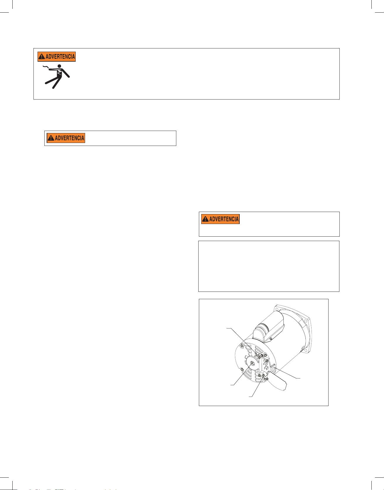
Grounding
1. Per manently ground the motor using the green ground
screw, as shown below. Use the correct wire size
and type specified by National Electrical Code. Be
sure the ground wire is connected to an electrical
service ground.
2. The pump should be permanently connected to either
a circuit breaker, 2-pole timer or 2-pole relay.
Note: If AC power is supplied by a GFCI circuit breaker,
the pump should be wired on its own independent
circuit unless the pump is operated in tandem
with a Pentair salt chlorine generator.
Section P/N 350486 Rev. D 4/9/19
Bonding
Lug
Motor Shaft
Slot for 3/8” or
1/2” Flathead
Screwdriver
Ground
Screw
1/2” NPT
Receptacle
for Liquid
Tight
Connector
Page 9
WATERFALL™ Specialty Pump Installation and User’s Guide
ENGLISH
OPERATING THE PUMP
Initial Start-Up
1. Relieve all system pressure and open all air bleeders on entire hydraulic system prior to starting the
Waterfall™ Specialty Pump. See filter owner’s manual.
2. Ensure that all fittings, clamps, closures and couplings are tight and in accordance with equipment
manufacturer’s recommendations.
3. Open suction and discharge valve to allow free flow of water. On flooded suction pumps with strainer pot, the
water source is higher than the pump. The water will flow into the pump strainer pot and the pot will fill with
water. On pumps without strainer pot, the water will fill the pump housing.
4. On non-flooded suction systems, the pump lid will have to be removed by rotating the lid counter-clockwise
and lifting.
5. The pump strainer pot should be filled with water up to suction/inlet port on the pump.
6. It is good practice to lubricate the lid o-ring with silicone lubricant each time the lid is removed. The o-ring
should be cleaned and inspected every time the strainer pot is opened.
7. The lid should be replaced by pressing the lid down and twisting the lid clockwise.
8. The pump is now ready to prime. Energize the motor and the pump will prime. The time to prime will depend
on the suction lift and the distance and size of suction piping. Turn off power if the pump does not prime
within thirty (30) minutes and refer to “Troubleshooting” on page 12.
5
DO NOT run the pump dry. If the pump is run dry, the mechanical seal will be damaged and the pump will start
leaking. If this occurs, the damaged seal must be replaced. ALWAYS maintain proper water level in your pool
(half way up skimmer opening). If the water level falls below the skimmer opening, the pump will draw air through the skimmer,
losing the prime and causing the pump to run dry, resulting in a damaged seal. Continued operation in this matter could cause a
loss of pressure, resulting in damage to the pump case, impeller, and seal and may cause property damage and personal injury.
Page 10
6
WATERFALL™ Specialty Pump Installation and User’s Guide
MAINTENANCE
This section describes how to maintain the Waterfall™ Specialty Pump.
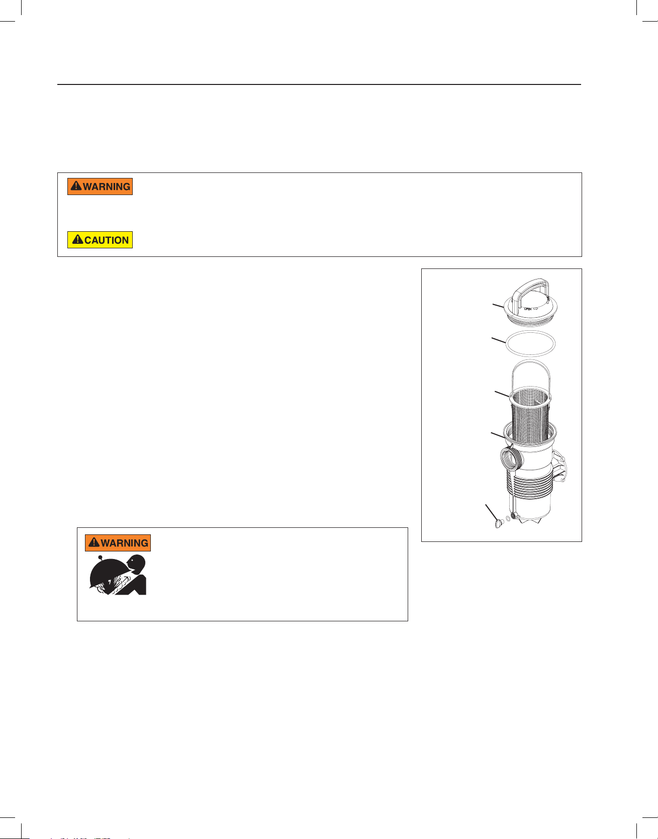
Cleaning the Pump Strainer Basket
The strainer basket in the pump should be visually inspected at least once a week. Remove the clear lid and the
basket and clean debris from basket. Inspect the lid o-ring; if damaged replace. The pump seal requires no lubrication.
DO NOT open the strainer pot if pump fails to prime or if pump has been operating without water in the strainer
pot. Pumps operated in these circumstances may experience a build up of vapor pressure and may contain
scalding hot water. Opening the pump may cause serious personal injury. In order to avoid the possibility of personal injury, make
sure the suction and discharge valves are open and strainer pot temperature is cool to touch, then open with extreme caution.
To prevent damage to the pump and filter and for proper operation of the system, clean pump strainer and
skimmer baskets regularly.
1. Turn off the pump at the breaker.
2. Close the inlet and discharge valves.
3. Relieve pressure in the system.
4. Turn the strainer lid in a counter-clockwise direction to remove the lid and
remove the basket from the pump.
5. Remove the debris from the strainer basket and rinse out the basket. Replace
the basket if it is cracked.
6. Replace the basket.
7. Fill the pump strainer pot and volute up to the suction/inlet port with water.
8. Clean the lid, O-ring, and sealing surface of the strainer pot.
Note: It is important that the O-Ring be kept clean and well lubricated.
9. Reinstall the lid by placing the lid back onto the strainer pot and turning the
lid clockwise.
Note: Be sure the lid O-ring is properly placed around the entire sealing
surface of the strainer pot.
10. Open the inlet and discharge valves.
11. Turn the power “ON” at the circuit breaker.
Figure 3
THIS SYSTEM OPERATES UNDER HIGH PRESSURE.
When any part of the circulating system (e.g., Lock Ring,
Pump, Filter, Valves, etc.) is serviced, air can enter the
system and become pressurized. Pressurized air can
cause the lid to separate which can result in serious
injury, death, or property damage. To avoid this potential
hazard, follow these instructions.
Strainer
Lid
O-Ring
Strainer
Basket
Strainer
Pot
Drain Plug
12. Open the manual air relief valve on top of the filter.
13. Stand clear of the filter. Start the pump.
14. Bleed air from the filter until a steady stream of water comes out. Close the manual air relief valve.
Page 11

7
WATERFALL™ Specialty Pump Installation and User’s Guide
ENGLISH
Winterizing
You are responsible for determining when freezing conditions may occur. If freezing conditions are expected, take the
following steps to reduce the risk of freeze damage. Freeze damage is not covered under warranty.
In mild climates, when temporary freezing conditions may occur, run your filtering equipment all night to prevent
freezing.
To prevent freeze damage, follow the procedures below:
1. Shut off electrical power for the pump at the circuit breaker.
2. Drain the water out of the pump housing by removing the two thumb-twist drain plugs from the housing. Store
the plugs in the pump basket.
3. Cover the motor to protect it from severe rain, snow and ice.
Note: DO NOT wrap the motor with plastic or other air tight materials during winter storage. The motor may be
covered during a storm, winter storage, etc., but never when operating or expecting operation.
Motor Care
Protect from heat
1. Shade the motor from the sun.
2. Any enclosure must be well ventilated to prevent overheating.
3. Provide ample cross ventilation.
Protect against dirt
1. Protect from any foreign matter.
2. Do not store (or spill) chemicals on or near the motor.
3. Avoid sweeping or stirring up dust near the motor while it is operating.
4. If a motor has been damaged by dirt it may void the motor warranty.
5. Clean the lid and clamp, O-ring, and sealing surface of the pump pot.
Protect against moisture
1. Protect from continuous splashing or continuous sprayed water.
2. Protect from extreme weather such as flooding.
3. If motor internals have become wet - let it dry before operating. Do not allow the pump to operate if it has been flooded.
4. If a motor has been damaged by water it may void the motor warranty.
Note:
• DO NOT wrap motor with plastic or other air tight materials. The motor may be covered during a storm, for
winter storage, etc., but never when operating, or expecting operation.
• When replacing the motor, be certain that the motor support is correctly positioned to support the size of motor
being installed.
Page 12
8
WATERFALL™ Specialty Pump Installation and User’s Guide
SERVICING
This section describes how to service the Waterfall™ Specialty Pump.
RISK OF ELECTRICAL AND ELECTROCUTION
This pool pump must be installed by a licensed or certified electrician or a qualified pool serviceman
in accordance with the National Electrical Code and all applicable local codes and ordinances.
Improper installation will create an electrical hazard which could result in death or serious injury to
pool users, installers, or others due to electrical shock, and may also cause damage to property.
Always disconnect power to the pool pump at the circuit breaker before servicing the pump.
Failure to do so could result in death or serious injury to serviceman, pool users or others
due to electric shock.
Read all servicing instructions before working on the pump.
DO NOT open the strainer pot if pump fails to prime or if pump has been operating without water in
the strainer pot. Pumps operated in these circumstances may experience a build up of vapor pressure
and may contain scalding hot water. Opening the pump may cause serious personal injury. In order
to avoid the possibility of personal injury, make sure the suction and discharge valves are open and
strainer pot temperature is cool to touch, then open with extreme caution.
Be sure not to scratch or mar the polished shaft seal faces; seal will leak if faces are damaged.
Pump Disassembly
All moving parts are located in the rear sub-assembly of this pump. Refer to Figure 5 on page 10 for an illustrated
parts view.
Tools required:
• 1/4-inch Flat Blade Screwdriver
• 3/8-inch or 1/2-inch Flat Blade Screwdriver
• 9/16-inch Open End Wrench
• Rubber Mallet
• Adjustable Wrench or Locking Pliers
To remove and repair the motor sub-assembly perform the following procedures:
1. Turn off the pump circuit breaker at the main panel. Close suction and discharge valves to relieve system
pressure.
2. Drain the pump by removing the drain plugs. The drain plugs can be removed by hand. No tools are needed.
3. Loosen the band clamp by turning the band clamp knob counter-clockwise. The band clamp holds the rear subassembly to the housing (strainer pot/volute).
4. Remove the rear sub-assembly from the housing (strainer pot/volute) and place the band clamp to the side.
Note: If the band clamp does not separate from the pump housing and seal plate when loose, lightly tap the top of
the band clamp with a rubber mallet. This will free the clamp from the housing.
5. Place the rear sub-assembly upright and on a flat surface. Use a flat blade screwdriver to remove the three (3)
holding screws located on the diffuser.
6. Remove the diffuser and diffuser spacer from the rear sub-assembly.
7. Use a flat blade screwdriver to remove the impeller screw located in the center of the pump’s impeller.
Note: The impeller screw is a left-handed thread and loosens in a clockwise direction.
8. Use the 3/8-inch or 1/2-inch flat blade screwdriver to hold the motor shaft in place. The motor shaft is accessible
through the back of the motor.
Note: If the torque is too high to hold the screwdriver by hand then an adjustable wrench may be used to hold the
screwdriver shaft in place. Use locking pliers instead if your screwdriver has a round shaft.
Page 13
9
WATERFALL™ Specialty Pump Installation and User’s Guide
ENGLISH
Pump Disassembly (continued)
9. Unscrew the impeller from the motor shaft by twisting the impeller counter-clockwise.
10. Remove the rotating portion of the spring seal by hand.
Note: When placing the rotating seal to the side, ALWAYS place flat side down. The portion of the rotating spring
seal that contacts the white ceramic seal must be kept as free from contaminants (dust, dirt, debris, etc.) as possible.
11. Use the 9/16-inch wrench to remove the four (4) bolts that hold the motor to the seal plate.
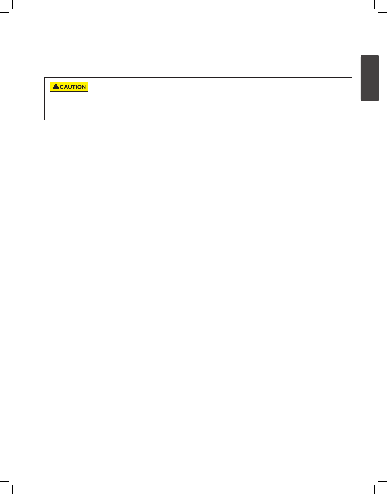
Shaft Seal Replacement
The mechanical seal can be changed without disconnecting piping by removing the band clamp and pulling the motor
with pump bracket diffuser and impeller assembly away from front pump housing body.
The Shaft Seal consists primarily of two parts, a rotating spring seal and a ceramic seal. See Figure 4.
The Waterfall™ Specialty Pump requires little or no service other than reasonable care, however, a Shaft Seal may
occasionally become damaged and must be replaced.
The polished and lapped faces of the seal could be easily damaged if not handled with care.
In mild climate area, when temporary freezing conditions may occur, run your filtering equipment all night to
prevent freezing.
To replace the pump seal:
12. Follow steps 1-11 in the “Pump Disassembly” section.
13. Place the seal plate face down on a flat surface and tap out the old ceramic seal.
14. Lubricate the seal seat with clean water.
15. Press the new ceramic seal into the seal plate with your thumbs and wipe off the white ceramic with a clean cloth.
16. Using a 9/16-inch wrench, remount the seal plate to the motor via the four (4) bolts that hold the motor to the seal plate.
17. Grease the motor shaft thread and continue with steps 2-10 from the “Pump Reassembly” section to reassemble
the pump.
Spring Seal Ceramic Seal
Figure 4
Page 14

10
WATERFALL™ Specialty Pump Installation and User’s Guide
Pump Reassembly
1. Use the 9/16-inch wrench to remount the seal plate to the motor via the four (4) bolts that hold the motor to the seal
plate.
2. Reseat the spring seal onto the white ceramic seal. Ensure that the carbon face of the spring seal contacts the
ceramic face of the stationary seat.
3. Grease the motor shaft thread and screw the impeller onto the motor shaft.
Note: Use the 3/8-inch or 1/2-inch flat blade screwdriver to hold the motor shaft in place when screwing down the
impeller. The motor shaft is accessible through the back of the motor.
4. Using a flat blade screwdriver, screw in the impeller lock screw.
Note: The impeller screw is a left-handed thread and tightens in a counter-clockwise direction.
5. Remount the diffuser spacer and diffuser using a flat blade screwdriver and the three (3) diffuser screws.
6. Reseat the pump housing (strainer pot/volute) onto the rear sub-assembly.
7. Place the band clamp around the pump housing an rear sub-assembly. Tighten with the band clamp knob.
Note: The band clamp knob should be parallel to the floor of the equipment pad when the clamp is installed properly.
8. Reinstall the drain plugs. Hand tighten only!
9. Fill the pump strainer pot with water.
10. Refer to page 5 “Initial Start-Up” procedures to restart the pump.
Figure 5
Page 15
11
WATERFALL™ Specialty Pump Installation and User’s Guide
ENGLISH
RESTART INSTRUCTIONS
If the Waterfall™ Specialty Pump is installed below the water level of the pool, close return and suction lines prior to
opening hair and lint pot on pump. Make sure to reopen valves prior to operating.
DO NOT run the pump dry. If the pump is run dry, the mechanical seal will be damaged and the pump will start
leaking. If this occurs, the damaged seal must be replaced. ALWAYS maintain proper water level in your pool
(half way up skimmer opening). If the water level falls below the skimmer opening, the pump will draw air through the skimmer,
losing the prime and causing the pump to run dry, resulting in a damaged seal. Continued operation in this matter could cause a
loss of pressure, resulting in damage to the pump case, impeller, and seal and may cause property damage and personal injury.
Priming the Pump
The pump strainer pot must be filled with water before the pump is initially started. Follow these steps to prime the pump:
1. Remove the pump lid.
2. Fill the pump strainer pot with water.
3. Reassemble the pump lid onto the strainer pot. The pump is now ready to prime.
4. Open the air release valve on the filter, and stand clear of the filter.
5. Turn on the switch or time clock.
6. When water comes out of the air release valve, close the valve. The system should now be free of air and recirculating
water to and from the pool.
7. This pump will prime within thirty (30) minutes. Do not allow your pump to run longer than this time without developing
full flow. If the pump does not prime, see “Troubleshooting” on page 12.
8. Two speed pumps should run on high speed for priming.
Page 16
12
WATERFALL™ Specialty Pump Installation and User’s Guide
TROUBLESHOOTING
Use the following troubleshooting information to resolve possible Waterfall™ Specialty Pump problems.
RISK OF ELECTRICAL SHOCK OR ELECTROCUTION.
Improper installation will create an electrical hazard which could result in death or serious injury to
pool users, installers, or others due to electrical shock, and may also cause damage to property.
1. If you are not familiar with your pool filtering system and/or heater:
a. DO NOT attempt to adjust or service without consulting your dealer, or a qualified
pool professional.
b. Read the entire Installation & User’s Guide before attempting to use, service or adjust
the pool filtering system or heater.
2. SWITCH OFF power to the pump at the breaker before attempting service or repair.
Problems and Corrective Actions
Problem Cause Remedy
Pump will not prime 1. No water in strainer pot. Add water to pot.
2. Strainer pot lid is not tight. Tighten lid.
3. Damaged lid o-ring. Replace o-ring.
4. Water level is below skimmer. Adjust pool water level.
5. Strainer basket or skimmer basket is clogged. Clear basket.
6. Closed valve in piping system. Check all valves and open all
necessary valves.
7. Pump is on low speed (two speed units only). Adjust to high speed.
8. Air leak in suction line. Find & fix leak.
Low Flow 1. Restriction in return line. Open return line restriction.
2. Strainer basket or skimmer basket is clogged. Clean basket.
3. Clogged impeller. Clean obstruction.
4. Air leak in suction line. Find & fix leak.
5. Restriction in suction line. Find and open restriction.
Motor does not turn 1. Power switch is off. Check power switch & reset.
2. Circuit breaker has tripped. Check circuit breaker & reset, if
re-trips, contact electrician.
3. Pump is in “Off-mode” on a timer controlled circuit. Check timer mode.
4. Motor terminal connections are incorrect. Have terminal connections checked by
electrician.
5. Motor shaft is locked by bad bearing. Have motor bearings replaced or
replace pump.
6. Impeller is locked by debris. Clean impeller.
Motor Over-Heating 1. Electrical supply connections are incorrect. Have terminal connections checked by
electrician.
2. Wiring to pump is undersized. Consult electrician to rewire pump.
3. Power Company supply voltage is low. Notify Power Company.
4. Ventilation is inadequate for motor. Remove any restrictions to air flow.
Page 17
13
WATERFALL™ Specialty Pump Installation and User’s Guide
ENGLISH
1
2
4
5
6
12
11
13
7
15
18
14
17
19
20
21
16
3
23
8
10
24
9
22
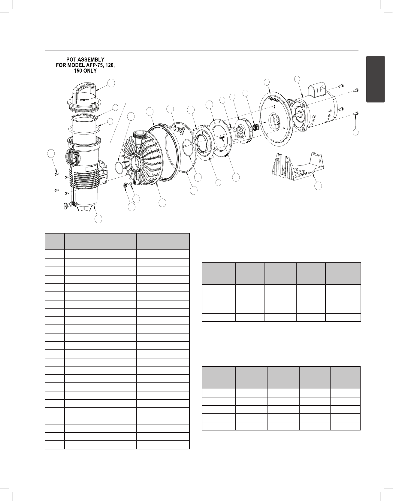
REPLACEMENT PARTS
ITEM
#
1 Motor See Motor Table
2 Seal Plate See Strainer Table
3 Motor Bolt (4x) 070429
4 Seal 354545S
5 Impeller See Motor Table
6 Nose Bearing 355142
7 Diffuser See Motor Table
8 Strainer Basket See Strainer Table
9 Lid O-ring 350013
10 Lid See Strainer Table
11 Impeller Screw 355389
12 Diffuser Spacer See Motor Table
13 Diffuser Screw (3x) 355141
14 Diffuser O-ring 355227
15 Seal Plate O-ring 355329
16 Housing See Strainer Table
17 Band Clamp 354629
18 Band Clamp Knob 175025
19 Base 355305
20 Drain Plug O-ring (2x) 192115
21 Drain Plug (2x) 357161
22 Front Housing O-ring 355330
23 Strainer Pot 355300
24 Strainer Pot Bolt (4x) 354265
DESCRIPTION
PART
NUMBERS
Motor Table
Model
AFP-75,
AF-75
AFP-120,
AF-120
AFP-150 356075** 355220 355140 355495
Motor
(Item #1)
356076* 355544 355545 355317
356076* 355068 355069 355495
Impeller
(Item #5)
Diffuser
(Item #7)
(*) - Replaced P/N 355218 after May 2019
(**) - Replaced P/N 355222 after May 2019
Strainer Table
Model
AFP-75 355303 355387 355301 355468
AFP-120 355497 355387 355301 355468
AFP-150 355497 355441 355300 355468
AF-75 355303 - - 355302
AF-120 355497 - - 355302
Seal Plate
(Item #2)
Strainer
Basket
(Item #8)
Lid
(Item #10)
Diffuser
Spacer
(Item #12)
Housing
(Item #16)
Page 18

1620 HAWKINS AVE., SANFORD, NC 27330 • (919) 566-8000
*355143*
10951 WEST LOS ANGELES AVE., MOORPARK, CA 93021 • (805) 553-5000
WWW.PENTAIR.COM
All Pentair trademarks and logos are owned by Pentair or one of its global aliates. Waterfall™ is a trademark of Pentair Water Pool and Spa, Inc. and/or
its aliated companies in the United States and/ or other countries. Unless expressly noted, names and brands of third parties that may be used in this
document are not used to indicate an aliation or endorsement between the owners of these names and brands and Pentair Water Pool and Spa, Inc.
Those names and brands may be the trademarks or registered trademarks of those third parties. Because we are continuously improving our products
and services, Pentair reserves the right to change specications without prior notice. Pentair is an equal opportunity employer.
© 2019 Pentair Water Pool and Spa, Inc. All rights reserved. This document is subject to change without notice.
P/N 355143 REV. D 5/17/19
Page 19

ENGLISH
ESPAÑOL
WATERFALL™
BOMBA ESPECIAL
MANUAL DE INSTALACIÓN
GUÍA DEL USUARIO
INSTRUCCIONES DE SEGURIDAD IMPORTANTES
LEA Y SIGA TODAS LAS INSTRUCCIONES
GUARDE ESTAS INSTRUCCIONES
Page 20

Manual de instalación y guía del usuario de la bomba especial WATERFALL™
i
SERVICIO AL CLIENTE / SOPORTE TÉCNICO
Si tiene dudas acerca de cómo pedir piezas de repuesto de Pentair y productos para piscina, comuníquese con:
Servicio al cliente y soporte técnico, EE. UU.
(8 a. m. a 7:30 p. m. hora del este/Pacífico)
Teléfono: (800) 831-7133
Fax: (800) 284-4151
Sitio web
Para obtener más información acerca de los
productos Pentair, visite www.pentair.com.
ÍNDICE
Advertencias e instrucciones de seguridad
importantes de la bomba .....................................
Introducción ..........................................................
Vista general de la bomba
Canasta del colador de la bomba
Instalación ............................................................
Ubicación
Selección de bomba y tubería
Instalación de tuberías, conexiones y válvulas
Instalación eléctrica
Cableado
Conexión a tierra
Empalmes
Funcionamiento de la bomba ..............................
Arranque inicial
Mantenimiento ......................................................
Limpieza de la canasta del colador
Preparación para el invierno
Cuidado del motor
Sanford, North Carolina (8 a. m. a 4:30 p. m. hora del este)
Teléfono: (919) 566-8000
Fax: (919) 566-8920
Moorpark, California (8 a. m. a 4:30 p. m. hora del Pacífico)
Teléfono: (805) 553-5000 (Ext. 5591)
Fax: (805) 553-5515
Servicio ...............................................................
ii
1
1
1
2
2
2
3
4
4
4
4
5
5
6
6
7
7
Desmontaje de la bomba
Reemplazo del sello del eje
Volver a montar la bomba
Instrucciones de reinicio ...................................
Cebado de la bomba
Solución de problemas ......................................
Piezas de reemplazo ..........................................
8
8
9
10
11
11
12
13
P/N 355143 Rev. D 5/17/19
Page 21

Manual de instalación y guía del usuario de la bomba especial WATERFALL™
ENGLISH
ESPAÑOL
ADVERTENCIAS E INSTRUCCIONES DE SEGURIDAD IMPORTANTES DE LA BOMBA
PELIGRO
PELIGRO
F
PELIGRO
Advertencias generales
NOTA IMPORTANTE
Esta guía ofrece las instrucciones de instalación y operación para este producto.
Consulte a Pentair por cualquier pregunta relacionada con este equipo.
Atención, instalador: Esta guía contiene información importante sobre
la instalación, la operación y el uso seguro de este producto. Se le debe
proporcionar esta información al dueño y/u operador del equipo luego de la
instalación o se debe dejar esta información encima o cerca de la bomba.
Atención, usuario: Este manual contiene información importante que
le ayudará a operar y mantener este producto. Por favor, consérvelo para
futura referencia.
LEA Y SIGA
TODAS LAS INSTRUCCIONES
GUARDE ESTAS INSTRUCCIONES
Este es el símbolo de alerta de seguridad. Cuando vea
este símbolo en su sistema o en este manual, busque
una de las siguientes palabras de señal y esté alerta a
la posibilidad de que alguna persona resulte lesionada.
Advierte sobre peligros que pueden causar la muerte,
serias lesiones personales o daños importantes a la
propiedad si se ignoran.
Advierte sobre peligros que pueden causar la muerte,
serias lesiones personales o daños importantes a la
propiedad si se ignoran.
Advierte sobre peligros que pueden provocar lesiones
personales leves o daños a la propiedad si son
ignorados.
NOTA indica instrucciones especiales no relacionadas con peligros.
Lea y siga cuidadosamente todas las instrucciones de seguridad en este
manual y en relación a los equipos. Conserve las etiquetas de seguridad
en buenas condiciones; reemplácelas si faltan o están dañadas.
• Nunca se debe abrir el interior del recinto del motor del accionador.
Hay un bloque de condensadores con una carga de 230 VCA incluso
cuando la unidad no está conectada a la fuente de alimentación.
• La bomba no es sumergible.
• La bomba puede alcanzar caudales de salida elevados; tenga cuidado
al instalar y programar el límite potencial de rendimiento de las bombas
con equipos antiguos o dudosos.
• Los códigos requeridos para la conexión eléctrica varian dependiendo
del país, estado o municipalidad local. Instale el equipo de acuerdo al
código de electricidad nacional y todos los demás códigos y normas
aplicables.
• Antes de efectuar el mantenimiento de la bomba; apague la alimentación
de energía eléctrica a la bomba desconectando el circuito principal
que va hacia la bomba.
• Este artefacto no debe ser utilizado por personas (incluyendo niños)
con capacidades físicas, sensoriales o mentales reducidas, o que no
tengan la experiencia y los conocimientos, a menos que hayan sido
supervisados o instruidos en el uso del artefacto por una persona
responsable por su seguridad.
EL INCUMPLIMIENTO DE TODAS LAS
INSTRUCCIONES Y ADVERTENCIAS PUEDE DAR
COMO RESULTADO LESIONES CORPORALES SERIAS O LA MUERTE.
ESTA BOMBA DEBE SER INSTALADA Y MANTENIDA ÚNICAMENTE POR
UN PROFESIONAL DE MANTENIMIENTO DE PISCINAS CUALIFICADO.
LOS INSTALADORES, OPERADORES DE PISCINAS Y DUEÑOS DEBEN
LEER ESTAS ADVERTENCIAS Y TODAS LAS INSTRUCCIONES EN
EL MANUAL DEL USUARIO ANTES DE USAR ESTA BOMBA. ESTAS
ADVERTENCIAS Y EL MANUAL DEL USUARIO DEBEN QUEDARSE
CON EL DUEÑO DE LA PISCINA.
PELIGRO DE ATASCAMIENTO: ¡MANTÉNGASE
ALEJADO DEL DRENAJE PRINCIPAL Y DE TODAS
LAS SALIDAS DE SUCCIÓN!
ii
Cuando instale y use estos equipos eléctricos, siempre se deben seguir las
precauciones de seguridad básicas, entre las que se incluye las siguientes:
No permita que los niños usen este producto.
RIESGO DE DESCARGA ELÉCTRICA. (Para todas las
unidades instaladas de manera permanente, diseñadas
para usarse en circuitos derivados monofásicos de 15 o 20 amperes y 125 a 240
voltios). Conecte solamente a un circuito derivado protegido por un interruptor
de circuito por falla a tierra (GFCI). Contacte a un electricista cualificado si no
puede verificar que el circuito esté protegido por un GFCI. Esta unidad debe
conectarse solamente a un circuito de alimentación protegido por un interruptor
de circuito por falla a tierra (GFCI). Dicho GFCI debe proporcionarlo el instalador
y debe ser sometido a pruebas de rutina. Para probar el GFCI, oprima el botón
de prueba. El GFCI debe cortar la energía. Oprima el botón de reanudar.
La energía debería restaurarse. Si el interruptor de circuito por falla a tierra
(GFCI) no puede funcionar de esta manera, el GFCI es defectuoso. Si el GFCI
interrumpe la alimentación a la bomba sin haberse oprimido el botón de prueba,
estará fluyendo una corriente a tierra, indicando la posibilidad de un choque
eléctrico. No use esta bomba. Desconecte la bomba y pídale a un representante
de servicio cualificado que corrija el problema antes de usarla.
Esta bomba es para ser utilizada en piscinas
permanentes y también puede usarse con jacuzzis y
spas, si así se especifica. No la use con piscinas que se deban almacenar.
Una piscina instalada permanentemente se construye en el suelo o en un
edificio de manera tal que no se pueda desmontar para ser almacenada.
Una piscina que se debe almacenar está construida con el fin de poder
desmontarla fácilmente para su almacenamiento y montarla nuevamente
con posterioridad.
ESTA BOMBA PRODUCE ALTOS NIVELES DE SUCCIÓN Y CREA UN
FUERTE VACÍO EN EL DRENAJE PRINCIPAL, EN LA PARTE INFERIOR
DE LA MASA DE AGUA. LA SUCCIÓN ES TAN FUERTE QUE PUEDE
ATRAPAR A ADULTOS O NIÑOS BAJO EL AGUA SI SE ENCUENTRA
PRÓXIMOS A UN DRENAJE O A UNA CUBIERTA O REJILLA ROTA O
SUELTA DEL DRENAJE.
EL USO DE CUBIERTAS INADECUADAS O PERMITIR EL USO DE LA
PISCINA O EL SPA CUANDO HAY CUBIERTAS AUSENTES, FISURADAS
O ROTAS PUEDE DAR COMO RESULTADO EL ATASCO DE ALGUNA
PARTE DEL CUERPO O ARTICULACIÓN, ENREDO DE CABELLO,
ATASCO DEL CUERPO, EVISCERACIÓN Y/O LA MUERTE.
La succión en el drenaje o salida puede causar:
Atascamiento de un miembro: Cuando un miembro del cuerpo es
succionado o insertado en una abertura y produce una obstrucción o
atrapamiento mecánico. Este peligro se presenta cuando la cubierta de
un drenaje falta, está rota, suelta, fisurada o incorrectamente asegurada.
Enredo de cabellos: Cuando el cabello se enreda o anuda en la cubierta del
drenaje y atrapa al nadador debajo del agua. Este peligro se presenta cuando
la velocidad del flujo de la cubierta es demasiado baja para la(s) bomba(s).
Atascamiento del cuerpo: Cuando una parte del cuerpo queda atrapada
contra la cubierta del drenaje manteniendo al nadador debajo del agua.
Este peligro se presenta cuando la cubierta del drenaje falta, está rota o
cuando la velocidad de flujo de la cubierta no es lo suficientemente alta
para la(s) bomba(s).
Evisceración/desentrañamiento: Cuando una persona se sienta en una
piscina abierta (particularmente una piscina de chapoteo para niños) o en la
salida de un spa y se aplica la succión directamente a los intestinos, causando
un daño intestinal severo. Este peligro se presenta cuando la cubierta del drenaje
falta, está suelta, fisurada o incorrectamente asegurada.
Page 22

Manual de instalación y guía del usuario de la bomba especial WATERFALL™
iii
PELIGRO
ADVERTENCIAS E INSTRUCCIONES DE SEGURIDAD IMPORTANTES DE LA BOMBA
Atrapamiento mecánico: Cuando las joyas, el traje de baño, los accesorios
para el cabello, lo dedos de manos o pies, o un nudillo se atascan en la abertura
de una salida o de una cubierta de drenaje. Este peligro se presenta cuando la
cubierta del drenaje falta, está suelta, rota, fisurada o incorrectamente asegurada.
NOTA: TODA LA FONTANERÍA DE SUCCIÓN DEBE INSTALARSE
EN CONFORMIDAD CON LOS ÚLTIMOS CÓDIGOS, ESTÁNDARES Y GUÍAS
NACIONALES Y LOCALES.
PARA MINIMIZAR EL RIESGO DE LESIONES DEBIDO
AL PELIGRO DE ATASCO POR SUCCIÓN:
• Para cada drenaje, se debe usar una cubierta de succión anti-atascos
apropiadamente instalada y asegurada y aprobada por el ANSI/ASME A112.19.8.
• Cada cubierta de succión debe ser instalada al menos a tres pies (3’) de
distancia, medidos desde el punto más cercano hasta el punto más cercano.
• Inspeccione todas las cubiertas con regularidad en busca de fisuras, daños e
intemperización avanzada.
• Si una cubierta está suelta, fisurada, dañada, rota o ausente, reemplácela con
una cubierta certificada apropiada.
• Reemplace la cubierta del drenaje según sea necesario. Las cubiertas del drenaje
se deterioran con el tiempo debido a la exposición a la luz solar y el clima.
• Evite que el cabello, los miembros superiores e inferiores o el cuerpo estén en
proximidad cercana a las cubiertas de succión, el drenaje o la salida de la piscina.
• Deshabilite las salidas de la succión o vuelva a configurar las entradas de retorno.
La Ley de Seguridad para Piscinas y Spas Virginia Graeme Baker (VGB) crea
nuevos requerimientos para los dueños y operadores de piscinas y spas comerciales.
Las piscinas o spas comerciales construidos el 19 de diciembre de 2008 o después
de esa fecha, deberán utilizar:
(A) Un sistema de drenaje principal sin capacidad de aislamiento con cubiertas
de salida de succión que cumplan con el ASME/ANSI A112.19.8a en relación a
aditamentos de succión para uso en piscinas, piscinas de chapoteo, spas y jacuzzis,
y, ya sea:
(i) Un sistema de liberación de vacío de seguridad (SVRS) que cumpla con el estándar
ASME/ANSI A112.19.17 de sistemas de seguridad de liberación del vacío (SVRS)
fabricados para sistemas de piscina, spa, jacuzzi y piscina de niños residenciales
y comerciales, y/o la especificación del estándar ASTM F2387 para sistemas de
seguridad de liberación del vacío (SVRS) fabricados para piscinas, spas y jacuzzis o
(ii) Un sistema de ventilación limitado por succión debidamente diseñado y
comprobado o
(iii) Un sistema de apagado de bomba automático.
Las piscinas o spas comerciales construidos antes del 19 de diciembre de 2008, con
una sola salida de succión sumergida deberán usar una cubierta de la salida de la
succión que cumpla con el ASME/ANSI A112.19.8a y, ya sea:
(A) Un sistema de liberación de vacío de seguridad (SVRS) que cumpla con las
normas ASME/ANSI A112.19.17 y/o ASTM F2387, o
(B) Un sistema de ventilación limitado por succión debidamente diseñado y
comprobado, o
(C) Un sistema de apagado de bomba automático, o
(D) Bocas sumergidas desactivadas, o
(E) Las salidas de succión se deben configurar nuevamente como entradas de retorno.
Para la instalación de los controles eléctricos en la plataforma del equipo
(interruptores de encendido/apagado, temporizadores y centro de carga
automatizada)
Instale todos los controles eléctricos en la plataforma del
equipo, como los interruptores de encendido/apagado (ON/
OFF), los cronómetros y los sistemas de control, etc. para
permitir la operación (arranque, cierre o mantenimiento)
de cualquier bomba o filtro para que el usuario no coloque
ninguna porción de su cuerpo sobre o cerca de la tapa
coladora de la bomba, la tapa del filtro o los cierres de
la válvula. Esta instalación debe otorgar al usuario suficiente espacio para
mantenerse alejado del filtro y la bomba durante el arranque del sistema, el cierre
o el mantenimiento del filtro del sistema.
Debe haber un interruptor de cierre de emergencia
claramente etiquetado para la bomba en un lugar obvio
y de fácil acceso. Asegúrese que los usuarios sepan dónde está y cómo usarlo
en caso de emergencia.
PRESIÓN PELIGROSA: MANTENGA DISTANCIA DE
LA BOMBA Y EL FILTRO DURANTE EL ARRANQUE
Los sistemas de circulación funcionan bajo alta presión.
Cuando se hace mantenimiento a una parte del sistema
de circulación (es decir, el anillo de bloqueo, la bomba,
el filtro, las válvulas, etc.), el aire puede ingresar al
sistema y presurizarse. El aire presurizado puede hacer
que las válvulas y la tapa del filtro de la cubierta de la carcasa de la bomba se
separen violentamente, lo que puede ocasionar lesiones personales severas
o la muerte. La tapa del tanque del filtro y la cubierta del colador deben estar
correctamente aseguradas para evitar la separación violenta. Manténgase
alejado de los equipos del sistema de circulación de aire cuando encienda o
haga arrancar la bomba.
Antes de efectuar el mantenimiento a los equipos, tome nota de la presión del
filtro. Asegúrese de que todos los controles estén configurados para garantizar
que el sistema no arranque inadvertidamente durante el mantenimiento. Apague
toda alimentación a la bomba. IMPORTANTE: Coloque la válvula manual
de alivio de aire del filtro en posición abierta y espere que se alivie toda
la presión que se encuentra en el sistema.
Antes de hacer arrancar el sistema, abra completamente la válvula manual de
alivio de aire y coloque todas las válvulas del sistema en la posición abierta
para permitir que el agua fluya libremente desde el tanque y de regreso a él.
Manténgase alejado de todos los equipos y encienda la bomba.
IMPORTANTE: No cierre la válvula manual de alivio de aire del filtro hasta
que toda la presión haya sido descargada de la válvula y que aparezca
una corriente constante de agua. Observe el medidor de presión del filtro y
asegúrese de que no sea más alta que la condición previa al mantenimiento.
Información de instalación general
• Todo el trabajo debe realizarlo un profesional de servicio cualificado, y debe
cumplir con todos los códigos nacionales, estatales y locales.
• Instale de manera tal que haya drenaje del compartimiento para los
componentes eléctricos.
• Estas instrucciones contienen información para una variedad de modelos
de bombas y por tanto algunas instrucciones podrían no aplicarse a un
cierto modelo específico. Todos los modelos han de usarse en piscinas. La
bomba funcionará correctamente solamente si tiene el tamaño adecuado
en relación a la aplicación y si está apropiadamente instalada.
Las bombas de tamaño incorrecto o mal instaladas
o que se usen con aplicaciones diferentes a las que
fueron diseñadas para la bomba pueden provocar graves lesiones personales
o la muerte. Estos riesgos pueden incluir, entre otros, choques eléctricos,
incendios, inundaciones, atascamientos por succión o lesiones graves o
daños a la propiedad provocados por una falla estructural de la bomba u otro
componente del sistema.
La bomba puede producir altos niveles de succión del
lado de la succión del sistema de conexiones. Estos
niveles elevados de succión pueden representar un riesgo si una persona
se encuentra muy cerca de las aberturas de succión. La persona puede
lesionarse seriamente debido a este alto nivel de vacío, o puede atascarse y
ahogarse. Es absolutamente crítico que las conexiones de succión se instalen
de acuerdo con los códigos nacionales y locales para piscinas más recientes.
Las bombas y los motores de repuesto con velocidad única y un
(1) HP total o superior no se pueden vender, poner a la venta o
instalar en un grupo residencial para su uso en California, Título
20 del CCR, secciones 1601-1609.
Las advertencias y las instrucciones de seguridad para las bombas y otros
productos relacionados de Pentair Water Pool and Spa, Inc. se encuentran
disponibles en:
http://www.pentairpool.com/pool-owner/safety-warnings/ o llame al
(800) 831-7133 para obtener copias adicionales y gratuitas de las instrucciones.
Consulte en http://www.pentairpool.com/pool-owner/safety-warnings/ para
ver las instrucciones de advertencia y seguridad relacionadas con este producto.
Warning Page P/N 352557 Rev. C 7/18
Page 23

Manual de instalación y guía del usuario de la bomba especial WATERFALL™
ENGLISH
ESPAÑOL
INTRODUCCIÓN
Vista general de la bomba
Las bombas para piscinas comunes están diseñadas para que el agua circule a través de sistemas de tuberías con
pérdidas relativamente altas, lo que incluye muchas restricciones con respecto a las tuberías (por ejemplo, filtro para
piscinas, válvulas, calentador, conexiones para tuberías pequeñas, etc.) y, por lo tanto, deben generar una cantidad
significativa de presión para empujar el agua a través de todos los componentes. Si se instalan en sistemas de
tuberías que no tienen estos tipos de restricciones, las bombas para piscina tendrán un funcionamiento muy ruidoso
y a veces dañan el sistema mediante la cavitación.
La bomba especial Waterfall™ está específicamente diseñada para estos tipos de aplicaciones donde se necesita
suministrar el agua de manera silenciosa y eficiente a través de sistemas de tuberías con bajas restricciones. Estas
aplicaciones suelen requerir una bomba para crear efectos visuales como saltos, cascadas y aliviaderos, o cuando el
agua debe ser trasladada una distancia relativamente corta.
Esta bomba no está diseñada para usar como una bomba de filtración para piscinas común o en aplicaciones para
spa donde se requiere presión. Tampoco está diseñada para usar en sistemas donde se debe elevar el agua a más
de 10 pies (3 metros) sobre el depósito de la piscina.
Canasta del
colador
1
Bomba especial Waterfall
Canasta del colador de la bomba
La canasta del colador, conocida algunas veces como el ‘colector de cabello y pelusa’, se encuentra delante de
la carcasa de la bomba. La canasta, que debe estar siempre libre de hojas y residuos, se encuentra dentro de la
cámara.
Independientemente de cuánto tiempo pase entre limpiezas del filtro, es muy importante realizar una inspección
visual del colector de cabello y pelusa al menos una vez por semana. Una canasta sucia reducirá la eficiencia del
filtro y del calentador, además de que provocará un esfuerzo anormal en el motor de la bomba.
Page 24

2
Manual de instalación y guía del usuario de la bomba especial WATERFALL™
3 IN.
(7.6 CM)
MÍNIMO
5 x DIÁMETRO DE
TUBERÍA DE SUCCIÓN
CODO
12 IN
(30.5 CM)
MÍNIMO
INSTALACIÓN
Ubicación
Asegúrese de que la ubicación de la bomba especial
Waterfall™ cumpla con los siguientes requerimientos:
Nota: No instale esta bomba dentro de un
compartimiento externo o bajo el faldón de un
jacuzzi o spa, a menos que se marque de manera
correspondiente.
1. Instale la bomba tan cerca como pueda de la
piscina o spa. Para reducir la pérdida de fricción
y mejorar la eficiencia, use retornos de tubería de
succión corta y directa.
2. Instale como mínimo a 5 pies (1.5 metros) de la pared interna de la piscina o spa. Las instalaciones canadienses
requieren un mínimo de 9.8 pies (3 metros) desde el agua de la piscina.
3. Instale la bomba a un mínimo de 3 pies (0.9 metros) desde la salida del calentador.
4. No instale la bomba a más de 5 pies (1.5 metros) sobre el nivel del agua.
5. Instale la bomba en un lugar bien ventilado y protegido de la humedad excesiva (es decir, de desagües de
canaletas para la lluvia, rociadores de agua, etc.).
6. Instale la bomba con una holgura trasera de por lo menos 3 pulgadas (7.6 cm) para poder quitar el motor
fácilmente a fin de realizar su mantenimiento o reparación. Se requiere una holgura vertical de 12 pulgadas (30.5
cm) para quitar la canasta del colador. Véase la Figura 1.
Figura 1
Selección de bomba y tubería
Muchas instalaciones necesitan que la bomba eleve el agua varios pies para suministrar agua para una cascada o
decorativos acuáticos similares. Para esta elevación se necesita energía y, por lo tanto, se reduce la cantidad de flujo
que la bomba puede suministrar. Consultar la Tabla 1 para calcular la pérdida de flujo.
Siempre se recomienda que se calcule y se compare la pérdida de carga del sistema total con la curva de
rendimiento de la bomba antes de seleccionar los tamaños de la bomba y de la tubería. Sin embargo, la Tabla 2 se
puede usar como guía rápida para seleccionar la bomba y el tamaño de las tuberías en instalaciones simples.
Tabla 1: Efecto del cambio de elevación en el
Cambio de
elevación
Más de 15’
Menos
de 2’
2’ - 4’
4’ - 10’
10’ - 15’
flujo
Efecto en el flujo
Reducción insignificante del flujo si se instalan las
tuberías según las instrucciones.
Reducción leve del flujo si se instalan las tuberías
según las instrucciones.
El flujo se reduce entre 50 y 90% del índice
máximo, según la elevación exacta y la instalación
del sistema. Se debe determinar la pérdida de
carga del sistema de tubería para calcular el flujo.
Por lo general, no se recomienda.
El flujo se puede reducir hasta 50% o menos del
índice máximo.
Esta pérdida puede resultar aceptable en ciertas
aplicaciones de bajo flujo.
No se recomienda. No es posible el flujo con un
cambio de elevación mayor de 27’.
Tabla 2: Recomendaciones para el tamaño de
las tuberías
Modelo de
bomba
AF-75
AFP-75
AF-120
AFP-120
AFP-150 150 GPM 2-1/2” 3”
* El flujo máximo estimado es el flujo aproximado que la bomba puede descargar
a través de un sistema corto de tubería de “flujo alto”. La bomba generará flujos
de agua más bajos si tiene que elevar el agua a una mayor altura y/o hacer
circular el agua a través de un sistema de tuberías largo.
** Se pueden usar tuberías de tamaño mínimo en instalaciones donde el sistema
de tuberías es muy corto y directo, con pocas partes o codos. En aplicaciones
donde es importante lograr el máximo flujo de agua posible, siempre se deben
usar tuberías más grandes de “flujo alto”.
Flujo máximo*
estimado
75 GPM 1-1/2” 2”
120 GPM 2” 2-1/2”
Tamaño de
tuberías
mínimo**
Tamaño de
tuberías de flujo
alto
Page 25

Manual de instalación y guía del usuario de la bomba especial WATERFALL™
ENGLISH
ESPAÑOL
Instalación de tuberías, conexiones y válvulas
1. Use cinta de sello de rosca o selladores de tubo en todas las conexiones macho de los tubos y accesorios. Use
solo compuestos selladores de tubo adecuados para la tubería de plástico. NO USE LOS PRODUCTOS A BASE
DE PETRÓLEO.
2. Apoye el tubo para evitar tensiones en el filtro, la bomba y las válvulas del sistema.
3. Cuando conecte un conjunto de unión a la bomba, aplique un sellador de tubo a las roscas y luego apriete a
mano 1½ vuelta adicional. NO APRIETE EXCESIVAMENTE.
4. Los tendidos largos de tubería y los codos obstruyen el flujo. Para una mejor eficiencia, use la menor cantidad de
conexiones posibles, un tubo de diámetro grande (por lo menos 1.5 pulgadas) y coloque el equipo lo más cerca
posible de la piscina. La línea de succión de la bomba no debe ser más pequeña que el tamaño del tubo en la
entrada de la bomba.
5. Las conexiones de succión deben cumplir con los estándares ASME/ANSI A 112.19.8 M. Use conexiones de
succión doble.
6. Para la mayoría de las instalaciones que Pentair recomienda instalar una válvula en la aspiración de la bomba
y mangueras de retorno para que la bomba puede ser aislada durante el mantenimiento rutinario. Sin embargo,
recomendamos que una válvula, codo o tee instalado en la línea de succión debe ser no más cerca de la parte
delantera de la bomba de cinco 5 veces la línea de succión de diámetro. Ver Figura 1 en la página anterior.
Ejemplo: Un tubo de 1.5 pulgadas requiere una distancia de 7.5 pulgadas (19 cm) del frente de la entrada de
succión de la bomba. Esto ayudará a que la bomba cebe más rápido y dure más.
Nota: No instale codos de 90° directamente en la entrada o toma de corriente de la bomba.
7. La presión de funcionamiento máxima de esta bomba es de 50 PSI. NUNCA se debe hacer funcionar esta
bomba por encima de esta presión.
8. Esta bomba NO está diseñada para un funcionamiento en serie con otras bombas.
3
Page 26
4
Manual de instalación y guía del usuario de la bomba especial WATERFALL™
Tornillo
a tierra
Ranura del eje
del motor para
destornillador
de cabeza plana
de 1/2” o 3/8”
Lengüeta
de empalme
Receptáculo
con tubo de
1/2" NPT para
conector de
líquido
Instalación eléctrica
RIESGO DE DESCARGA ELÉCTRICA O ELECTROCUCIÓN. Esta bomba debe ser instalada por un electricista con licencia o certificado o
por un profesional de servicios calificado conforme al Código Nacional de Electricidad (NEC) y los códigos y las ordenanzas locales aplicables.
Una instalación inadecuada generará un riesgo eléctrico que podría causar la muerte o lesiones graves a usuarios, instaladores y otras
personas debido a una descarga eléctrica, y también podría provocar daños a la propiedad.
Desconecte siempre la bomba desde el interruptor de circuito antes de realizarle el servicio. No hacerlo podría causar la muerte o
lesiones graves a las personas que realizan el servicio, a los usuarios u otras personas debido a una descarga eléctrica.
Lea todas las instrucciones de servicio antes de trabajar en la bomba.
Cableado
1. Verifique que todos los interruptores, disyuntores y controles
automáticos estén apagados antes de conectar el motor.
CARGA GUARDADA: espere al menos
sesenta (60) segundos antes de realizar el servicio.
2. Conozca el diagrama de cableado, los voltios, hertz,
amperios y fases del motor de su bomba en particular. Toda
la información figura en la placa de identificación que está
sobre un lado del motor.
3. Verifique que la tensión de alimentación cumpla con los
requisitos que aparecen en la placa del motor. Si no se
cumplen, se puede producir un daño permanente en el motor.
4. Para conocer el calibre de los cables y las pautas
generales para una instalación eléctrica adecuada, siga
las especificaciones definidas por el Código Nacional de
Electricidad y cualquier otro código nacional o local de
aplicación.
5. Los motores trifásicos necesitan protección externa contra
golpes de tensión. Es necesario hacer una inspección inicial
para garantizar que la bomba rote correctamente.
Una vez instalada, inicie el ciclo momentáneamente. Para ello
enciéndala y apáguela. Observe la rotación del ventilador o
del eje del motor cuando se detiene. Si está correctamente
conectado, el eje y/o el ventilador coincidirán con la flecha
de rotación que tiene la bomba.
6. Use un aliviador de tensión y verifique que todas las
conexiones eléctricas estén limpias y ajustadas.
7. Corte los cables de la longitud apropiada para que no
se superpongan ni entren en contacto al momento de
conectarlos.
Empalmes
1. Empalme el motor a la estructura según el Código Nacional
de Electricidad y todos los códigos nacionales o locales de
aplicación. Utilice un conductor de empalme de cobre sólido no
inferior a 8 AWG. Para las instalaciones canadienses se debe
usar un conductor de empalme de cobre sólido de 6 AWG o
más. Instale un cable desde el tornillo o la lengüeta de empalme
externos hasta la estructura de empalme.
2. Conecte el cable de la lengüeta de empalme accesible del motor
a todas las partes metálicas de la estructura de la piscina, el
spa o el jacuzzi y a todos los equipos eléctricos, conductos de
metal y tuberías de metal que estén a unos 5 pies (1.52 metros)
de las paredes internas de la piscina, el spa o el jacuzzi. Instale
un cable desde el tornillo o la lengüeta de empalme externos
hasta la estructura de empalme.
Antes de conectar o reconectar la bomba verifique que
todas las conexiones eléctricas estén firmes y todas
las cubiertas compartimientos eléctricos y de cableado estén correctamente
instaladas.
Nota: Cuando la bomba se arranque o se detenga cortándole la
energía con un relé o temporizador, se deberá usar un dispositivo
de dos polos para aplicar y quitar la energía a ambos TERMINALES
DEL CABLE DE ENERGÍA.
Pentair ofrece interruptores GFCI que ofrecen la protección
personal adecuada y además cumplen con las normas de NEC
de 2008 a la fecha para bombas para piscina. Vea el catálogo de
productos Pentair para obtener más detalles.
Figura 2
Conexión a tierra
1. Conecte el motor a tierra de forma permanente mediante
el tornillo verde de conexión a tierra, como se muestra
debajo. Use el calibre y tipo de cable correctos, según lo
especifica el Código Nacional de Electricidad. Verifique
que el cable a tierra esté conectado a una conexión a
tierra del servicio eléctrico.
2. La bomba debe estar conectada permanentemente a un
interruptor de circuito, un temporizador de 2 polos o a un
relé de 2 polos.
Nota: Si la CA se obtiene de un interruptor de circuito
GFCI, el cableado de la bomba debe tener su propio
circuito independiente a menos que la bomba opere en
conjunto con un clorinador de sal de Pentair.
Section P/N 350486 Rev. D 4/9/19
Page 27

Manual de instalación y guía del usuario de la bomba especial WATERFALL™
ENGLISH
ESPAÑOL
FUNCIONAMIENTO DE LA BOMBA
Arranque inicial
1. Libere toda la presión del sistema y abra todos las purgas de aire en el sistema hidráulico antes de arrancar
la bomba especial Waterfall™. Vea el manual de propietario del filtro.
2. Asegúrese de que todas las conexiones, abrazaderas, cierres y uniones sean firmes y cumplan con las
recomendaciones del fabricante del equipo.
3. Abra la válvula de succión y de descarga para permitir el flujo libre de agua. En las bombas de succión
inundadas con recipiente del colador, la fuente de agua está a más altura que la bomba. El agua fluirá hacia
el recipiente del colador de la bomba y este se llenará de agua. En bombas sin recipiente del colador, el
agua llenará la carcasa de la bomba.
4. En los sistemas de succión no inundados, será necesario quitar la tapa de la bomba girándola en sentido
contrario a las manecillas del reloj y levantándola.
5. El recipiente del colador de la bomba se debe llenar con agua hasta el puerto de succión/entrada en la
bomba.
6. Es una buena práctica lubricar la junta tórica de la tapa con lubricante de silicona cada vez que se quite la
tapa. Se deberá limpiar e inspeccionar la junta tórica cada vez que se abra el recipiente del colador.
7. Se deberá reemplazar la tapa presionándola hacia abajo y girándola en el sentido de las manecillas del reloj.
8. Ahora la bomba está lista para el cebado. Encienda el motor y la bomba comenzará a cebarse. El tiempo de
cebado dependerá de la elevación de la succión y la distancia y el tamaño de la tubería de succión. Apague
la bomba si no se ceba en menos de treinta (30) minutos y consulte la sección “Solución de problemas” en la
página 12.
5
NO haga funcionar la bomba en seco. Si la bomba funciona en seco, el sello mecánico se dañará y
la bomba empezará a presentar fugas. Si esto ocurre, se debe reemplazar el sello dañado. SIEMPRE
mantenga el nivel de agua adecuado en su piscina (hasta la mitad de la abertura del colector de espuma). Si el nivel
de agua cae por debajo de la abertura del colector de espuma, la bomba tomará aire a través del colector de espuma,
con lo cual se perderá el cebado y hará que la bomba se seque y se dañe el sello. La operación continua de esta forma
podría provocar la pérdida de la presión, lo que dañaría la caja de la bomba, el impulsor y el sello y podría ocasionar
daños a la propiedad y lesiones personales.
Page 28
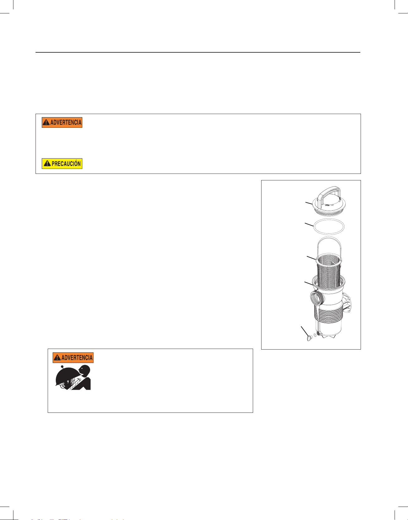
6
Manual de instalación y guía del usuario de la bomba especial WATERFALL™
MANTENIMIENTO
Esta sección describe cómo dar mantenimiento a la bomba especial Waterfall™.
Limpieza de la canasta del colador de la bomba
La canasta del colador en la bomba deberá inspeccionarse visualmente por lo menos una vez por semana. Quite la
tapa transparente y la canasta y limpie el residuo de la canasta. Inspeccione la junta tórica de la tapa; si está dañada,
reemplácela. El sello de la bomba no requiere lubricación.
NO abra el receptáculo para el colador si la bomba no ceba o si la bomba ha funcionado sin agua en dicho
receptáculo. Las bombas que funcionan bajo estas condiciones pueden acumular presión de vapor y contener
agua hirviendo. Abrir la bomba puede ocasionar graves lesiones personales. Con el fin de evitar la posibilidad de lesiones
personales, asegúrese de que las válvulas de succión y descarga estén abiertas y la temperatura del receptáculo para el colador
esté fría al tacto, entonces abra con mucho cuidado.
Para evitar que la bomba y el filtro se dañen, y para utilizar el sistema correctamente, limpie regularmente el
colador de la bomba y las canastas del desnatador
1. Apague la bomba en el disyuntor térmico.
2. Cierre las válvulas de entrada y descarga.
3. Libere la presión en el sistema.
4. Gire la tapa del colador en dirección contraria a las manecillas del reloj para
quitar la tapa y retire la canasta de la bomba.
5. Quite los residuos de la canasta del colador y enjuague la canasta. Reemplace
la canasta si estuviera rajada.
6. Reemplace la canasta.
7. Llene el recipiente del colador de la bomba y la voluta hasta el puerto de
succión/entrada con agua.
8. Limpie la tapa, la junta tórica y la superficie de sellado del recipiente del
colador.
Nota: Es importante mantener la junta tórica limpia y bien lubricada.
9. Para reinstalar la tapa, colóquela de vuelta en el recipiente del colador y
gírela en el sentido de las manecillas del reloj.
Nota: Asegúrese de que la junta tórica esté colocada correctamente alrededor
de toda la superficie de sellado del recipiente del colador.
10. Abra las válvulas de entrada y de descarga.
11. Encienda la alimentación en el disyuntor térmico del circuito.
Tapa del
colador
Junta tórica
Canasta del
colador
Colador
Balde
Tapón de
drenaje
Figura 3
ESTE SISTEMA FUNCIONA BAJO ALTA PRESIÓN.
Cuando cualquier parte del sistema de circulación (por
ej., el anillo de bloqueo, la bomba, el filtro, las válvulas,
etc.) recibe mantenimiento, puede ingresar aire al
sistema y presurizarse. El aire presurizado puede causar
que la cubierta se separe, y provocar lesiones graves,
muerte o daños a la propiedad. Para evitar este peligro potencial, siga
estas instrucciones.
12. Abra la válvula manual de alivio de aire que se encuentra encima del filtro.
13. Manténgase lejos del filtro. Inicie la bomba.
14. Purgue el aire del filtro hasta que salga una corriente constante de agua. Cierre la válvula manual de alivio de
aire.
Page 29

Manual de instalación y guía del usuario de la bomba especial WATERFALL™
ENGLISH
ESPAÑOL
Preparación para el invierno
Usted es responsable de determinar cuándo es probable que se produzcan condiciones de congelamiento. Si se
esperan temperaturas muy bajas, siga los pasos a continuación para reducir el riesgo de daños por congelamiento.
Los daños por congelamiento no están cubiertos por la garantía.
En climas moderados, en caso de posibles condiciones de congelamiento temporales, haga funcionar el equipo de
filtro toda la noche para evitar el congelamiento.
Para evitar los daños por congelamiento, siga los procedimientos a continuación:
1. Apague la corriente eléctrica de la bomba en el disyuntor.
2. Retire los dos tapones de drenaje manual de la carcasa para drenar el agua de la carcasa de la bomba. Coloque
los tapones en la canasta de la bomba.
3. Cubra el motor para protegerlo de lluvia fuerte, nieve y escarcha.
Nota: NO envuelva el motor con plástico u otros materiales herméticos cuando almacene la bomba en invierno.
Se puede cubrir el motor durante una tormenta, para su almacenamiento en invierno, etc., pero nunca mientras
esté en funcionamiento o esperando entrar en funcionamiento.
Cuidado del motor
Protección contra el calor
1. Proteja el motor del sol.
2. Mantenga todos los recintos bien ventilados para evitar el sobrecalentamiento.
3. Proporcione suficiente ventilación cruzada.
7
Protección contra la suciedad
1. Proteja de toda materia extraña.
2. No almacene (ni derrame) productos químicos sobre el motor o cerca de él.
3. Evite barrer o esparcir polvo cerca del motor mientras se encuentra en funcionamiento.
4. Si un motor resulta dañado por suciedad, puede resultar en la anulación de la garantía del motor.
5. Limpie la cubierta y la abrazadera, la junta tórica y la superficie de sellado del recipiente de la bomba.
Protección contra la humedad
1. Proteja de derrames continuos o de rocío continuo de agua.
2. Proteja de climas extremos como inundaciones.
3. Si el interior del motor se humedece, déjelo secar antes de utilizarlo. No permita que la bomba funcione si se ha
inundado.
4. Si un motor resulta dañado por agua, puede resultar en la anulación de la garantía del motor.
Nota:
• NO envuelva el motor con plástico u otros materiales herméticos. Se puede cubrir el motor durante una
tormenta, para su almacenamiento en invierno, etc., pero nunca mientras esté en funcionamiento o esperando
entrar en funcionamiento.
• Cuando reemplace el motor, asegúrese de que el soporte del mismo esté posicionado correctamente para
apoyar y soportar el motor que se va a instalar.
Page 30
8
Manual de instalación y guía del usuario de la bomba especial WATERFALL™
SERVICIO
Esta sección describe cómo dar servicio a la bomba especial Waterfall™.
RIESGO DE CHOQUE ELÉCTRICO Y ELECTROCUCIÓN
Esta bomba de piscina debe instalarla un electricista certificado o con licencia, o en todo caso, un
equipo profesional calificado de mantenimiento de conformidad con el Código Nacional Eléctrico
actual y todos los códigos y las ordenanzas locales aplicables. Una instalación incorrecta producirá
un peligro eléctrico que podría dar como resultado la muerte o una lesión seria a los usuarios de
la piscina, instaladores u otros debido a un choque eléctrico, y también podría causar daños a la
propiedad.
Siempre desconecte la alimentación de la bomba de piscina con el disyuntor térmico antes
de hacer un mantenimiento de la misma. Si no cumple con esto, podría resultar en muerte
o lesiones serias a la persona que realiza el mantenimiento, a los usuarios de la piscina o a
otros debido a una descarga eléctrica.
Lea todas las instrucciones de mantenimiento antes de trabajar con la bomba.
NO abra el receptáculo para el colador si la bomba no ceba o si la bomba ha funcionado sin agua
en dicho receptáculo. Las bombas que funcionan bajo estas condiciones pueden acumular presión
de vapor y contener agua hirviendo. Abrir la bomba puede ocasionar graves lesiones personales.
Con el fin de evitar la posibilidad de lesiones personales, asegúrese de que las válvulas de succión y
descarga estén abiertas y la temperatura del receptáculo para el colador esté fría al tacto, entonces
abra con mucho cuidado.
Asegúrese de no rayar o arruinar las superficies pulidas del sello del eje; el sello presentará fugas
si las superficies están dañadas.
Desmontaje de la bomba
Todas las partes móviles se encuentran en el subensamblaje trasero de la bomba. Consulte la Figura 5 en la página
10 para una vista ilustrada de las piezas.
Herramientas necesarias:
• Destornillador de punta plana de 1/4 de pulgada
• Destornillador de punta plana de 1/2 o 3/8 de pulgada
• Llave de boca de 9/16 de pulgada
• Mazo de goma
• Llave adjustable o pinzas de presión
Para quitar y reparar el subconjunto del motor, realice los siguientes procedimientos:
1. Apague el disyuntor térmico del circuito de la bomba en el panel principal. Cierre las válvulas de succión y
descarga para liberar la presión del sistema.
2. Retire los tapones de drenaje para drenar la bomba. Puede quitar los tapones de drenaje con la mano. No se
necesitan herramientas.
3. Afloje la abrazadera de la correa girando la perilla en sentido contrario a las manecillas del reloj. La abrazadera
de la correa sujeta el subensamblaje trasero con la carcasa (recipiente del colador/voluta).
4. Retire el subensamblaje trasero de la carcasa (recipiente del colador/voluta) y coloque la abrazadera de la correa
a un lado.
Nota: Si la abrazadera de la correa no se separa de la carcasa de la bomba y de la placa del sello cuando se
afloje, golpee ligeramente la parte superior de la abrazadera de la correa con un mazo de goma. Esto soltará la
abrazadera de la carcasa.
5. Coloque el subensamblaje trasero en posición vertical y sobre una superficie plana. Use un destornillador de
punta plana para quitar los tres (3) tornillos de sujeción ubicados en el difusor.
6. Quite el difusor y el espaciador de este del subensamblaje trasero.
7. Use un destornillador de punta plana para quitar el tornillo del impulsor que se encuentra en el centro del
impulsor de la bomba.
Nota: El tornillo del impulsor es de rosca izquierda y se afloja en el sentido de las manecillas del reloj.
Page 31

Manual de instalación y guía del usuario de la bomba especial WATERFALL™
ENGLISH
ESPAÑOL
Desmontaje de la bomba (continuación)
8. Use el destornillador de punta plana de 1/2 o 3/8 de pulgada para mantener el eje del motor en su lugar. Puede
acceder al eje del motor a través de su parte posterior.
Nota: Si el torque es demasiado alto como para poder sujetar el destornillador con la mano, puede usar una llave
ajustable para sujetar el eje del destornillador. Use pinzas de presión si su destornillador tiene un eje redondo.
9. Desenrosque el impulsor del eje del motor girándolo en sentido contrario a las manecillas del reloj.
10. Quite la parte giratoria del sello de resorte con la mano.
Nota: Cuando coloque el sello giratorio a un lado, SIEMPRE coloque el lado plano hacia abajo. La parte del
sello de resorte giratorio que hace contacto con el sello de cerámica blanco debe mantenerse lo más libre de
contaminantes (polvo, suciedad, residuos, etc.) que sea posible.
11. Use la llave de 9/16 de pulgada para quitar los cuatro (4) pernos que sujetan el motor a la placa del sello.
Reemplazo del sello del eje
Es posible cambiar el sello mecánico sin desconectar la tubería, quitando la abrazadera de la correa y jalando el
motor con el difusor del soporte de la bomba y el conjunto del impulsor para sacarlo del cuerpo delantero de la
carcasa de la bomba.
El sello del eje consiste principalmente de dos partes: el sello de resorte giratorio y un sello de cerámica. Véase la
Figura 4.
A excepción de un cuidado razonable, la bomba especial Waterfall™ precisa poco o nada de mantenimiento, aunque
el eje puede ocasionalmente dañarse y debe ser reemplazado.
9
Las superficies pulidas y plegadas del sello pueden dañarse fácilmente si no se manipulan con cuidado.
En zona de clima moderado, en caso de posibles condiciones de congelamiento temporales, haga funcionar el
equipo de filtro toda la noche para evitar el congelamiento.
Para reemplazar el sello de la bomba:
12. Siga los pasos 1-11 en la sección “Desmontaje de la bomba”.
13. Coloque la placa de sello hacia abajo en una superficie plana y golpee ligeramente el sello de cerámica viejo.
14. Lubrique el asiento del sello con agua limpia.
15. Presione el nuevo sello de cerámica dentro de la placa de sello con sus pulgares y limpie la cerámica blanca con
un paño limpio.
16. Use una llave de 9/16 de pulgada para volver a montar la placa del sello en el motor mediante los cuatro (4)
pernos que sujetan el motor a la placa del sello.
17. Engrase la rosca del eje del motor y continúe con los pasos 2 a 10 de la sección “Reensamblaje de la bomba”
para volver a ensamblar la bomba.
Sello de resorte Sello de cerámica
Figura 4
Page 32

10
Manual de instalación y guía del usuario de la bomba especial WATERFALL™
Volver a montar la bomba
1. Use la llave de 9/16 de pulgada para volver a montar la placa del sello al motor mediante los cuatro (4) pernos que
sujetan el motor a la placa del sello.
2. Vuelva a asentar el sello de resorte en el sello de cerámica blanca. Asegúrese de que la superficie de carbón del
sello de resorte esté en contacto con la superficie de cerámica del asiento fijo.
3. Engrase la rosca del eje del motor y atornille el impulsor en el eje del motor.
Nota: Use el destornillador de punta plana de 1/2 o 3/8 de pulgada para mantener el motor en su lugar cuando
atornille el impulsor. Puede acceder al eje del motor a través de su parte posterior.
4. Use un destornillador de punta plana para atornillar el tornillo de fijación del impulsor.
Nota: El tornillo del impulsor es una rosca izquierda y se aprieta en sentido contrario a las manecillas del reloj.
5. Vuelva a montar el espaciador del difusor y el difusor usando un destornillador de punta plana y los tres (3) tornillos
del difusor.
6. Vuelva a asentar la carcasa de la bomba (recipiente del colador/voluta) en el subensamblaje trasero.
7. Coloque la abrazadera de la correa alrededor de la carcasa de la bomba y del subensamblaje trasero. Apriete con
la perilla de la abrazadera de la correa.
Nota: La perilla de la abrazadera de la correa debe estar paralela al piso de la almohadilla del equipo cuando la
abrazadera se instale correctamente.
8. Vuelva a instalar los tapones de drenaje. ¡Apriete únicamente con la mano!
9. Llene el receptáculo del colador de la bomba con agua.
10. Consulte los procedimientos de “Arranque inicial” de la página 5 para reiniciar la bomba.
Carcasa de la bomba
Tapones de drenaje (x2)
Perilla de la
abrazadera
de sujeción
Abrazadera
de sujeción
Subensamblaje
Tornillo del
Difusor Impulsor
Tornillos de
sujeción para
difusor (x3)
trasero
impulsor
Sello
Espaciador
de difusor
Placa
selladora
Motor
Tornillos del
motor a la placa
selladora (x4)
Figura 5
Page 33
11
Manual de instalación y guía del usuario de la bomba especial WATERFALL™
ENGLISH
ESPAÑOL
INSTRUCCIONES PARA EL REINICIO
Si la bomba especial Waterfall™ se instala por debajo del nivel de agua de la piscina, cierre las líneas de retorno y de
succión antes de abrir el colector de cabello y pelusa en la bomba. Asegúrese de abrir nuevamente las válvulas antes
de poner en funcionamiento.
NO haga funcionar la bomba en seco. Si la bomba funciona en seco, el sello mecánico se dañará y la bomba
empezará a presentar fugas. Si esto ocurre, se debe reemplazar el sello dañado. SIEMPRE mantenga el nivel
de agua adecuado en su piscina (hasta la mitad de la abertura del colector de espuma). Si el nivel de agua cae por debajo de la
abertura del colector de espuma, la bomba tomará aire a través del colector de espuma, con lo cual se perderá el cebado y hará
que la bomba se seque y se dañe el sello. La operación continua de esta forma podría provocar la pérdida de la presión, lo que
dañaría la caja de la bomba, el impulsor y el sello y podría ocasionar daños a la propiedad y lesiones personales.
Cebado de la bomba
El receptáculo del colador de la bomba se debe llenar con agua antes del arranque inicial de la bomba. Siga estos
pasos para cebar la bomba:
1. Retire la cubierta de la bomba.
2. Llene el recipiente del colador de la bomba con agua.
3. Monte nuevamente la cubierta de la bomba en el recipiente del colador. La bomba está lista para el cebado.
4. Abra la válvula de liberación de aire en el filtro y mantenga distancia del filtro.
5. Gire el interruptor o el reloj de tiempo.
6. Cuando salga agua de la válvula de liberación de aire, cierre la válvula. El sistema debería ahora estar libre de aire
y recircular el agua desde la piscina y hacia ella.
7. Esta bomba se cebará en menos de treinta (30) minutos. No deje que la bomba funcione más de ese tiempo sin que
haya alcanzado un flujo completo. Si la bomba no se ceba, vea la sección “Solución de problemas” en la página 12.
8. Las bombas de dos velocidades deben funcionar en alta velocidad para el cebado.
Page 34

12
Manual de instalación y guía del usuario de la bomba especial WATERFALL™
SOLUCIÓN DE PROBLEMAS
Use la siguiente información de solución de problemas para resolver los posibles problemas de la bomba especial
Waterfall™.
RIESGO DE CHOQUE ELÉCTRICO O ELECTROCUTACIÓN.
Una instalación incorrecta producirá un peligro eléctrico que podría dar como resultado la muerte o una
lesión seria a los usuarios de la piscina, instaladores u otros debido a un choque eléctrico, y también
podría causar daños a la propiedad.
1. Si no está familiarizado con su sistema de filtrado de piscinas y/o calentador:
a. NO intente ajustar o dar servicio sin consultar con su distribuidor o con un profesional de
piscinas cualificado.
b. Lea todo el manual de usuario y la guía de instalación antes de usar, dar servicio o ajustar
el sistema de filtrado de piscina o el calentador.
2. DESCONECTE la alimentación eléctrica que va a la bomba en el disyuntor antes de
darle servicio o repararla.
Problemas y acciones correctivas
Problema Causa Solución
La bomba no se ceba 1. No hay agua en el recipiente del colador. Agregue agua al recipiente.
2. La tapa del recipiente del colador no está apretada. Apriete la tapa.
3. Junta tórica de la tapa dañada. Reemplace la junta tórica.
4. El nivel de agua está debajo del desnatador. Ajuste el nivel de agua de la piscina.
5. La canasta del colador o la canasta del desnatador Limpie la canasta.
están obstruidas.
6. Válvula cerrada en el sistema de tubería. Revise todas las válvulas y abra todas
las válvulas necesarias.
7. La bomba está en baja velocidad (unidades de dos Ajuste a velocidad alta.
velocidades solamente).
8. Fuga de aire en la línea de succión. Busque y corrija la fuga.
Flujo bajo 1. Obstrucción en la línea de retorno. Abra la obstrucción en la línea de retorno.
2. La canasta del colador o la canasta del desnatador Limpie la canasta.
están obstruidas.
3. Impulsor obstruido. Limpie la obstrucción.
4. Fuga de aire en la línea de succión. Busque y corrija la fuga.
5. Obstrucción en la línea de succión. Busque y abra la obstrucción.
El motor no gira 1. El interruptor de encendido está apagado. Revise el interruptor de encendido y
restablezca.
2. El interruptor del circuito se activó. Revise el disyuntor térmico del circuito y
restablezca, si se vuelve a activar, contacte
al electricista.
3. La bomba está en “modo de apagado” en un circuito Revise el modo del temporizador.
controlado por temporizador.
4. Las conexiones de las terminales del motor son Haga que un electricista revise las
incorrectas. conexiones de las terminales.
5. El eje del motor está bloqueado por un cojinete Mande reparar los cojinetes del motor o
defectuoso. reemplace la bomba.
6. El impulsor está bloqueado por residuos. Limpie el impulsor.
Sobrecalentamiento del motor 1. Las conexiones de alimentación eléctrica son Haga que un electricista revise las
incorrectas. conexiones de las terminales.
2. El cableado que va a la bomba es de tamaño muy Consulte al electricista para que vuelva a
pequeño. cablear la bomba.
3. El voltaje de alimentación de la compañía eléctrica Notifique a la compañía eléctrica.
es bajo.
4. La ventilación es inadecuada para el motor. Retire cualquier obstrucción del flujo de aire.
Page 35

13
Manual de instalación y guía del usuario de la bomba especial WATERFALL™
ENGLISH
ESPAÑOL
1
2
4
5
6
12
11
13
7
15
18
14
17
19
20
21
16
3
23
8
10
24
9
22
ENSAMBLAJE DE RECIPIENTE
PARA MODELO AFP-75, 120, 150
SOLAMENTE
PIEZAS DE REEMPLAZO
ARTÍCULO
#
1
2
3
4
5
6
7
8
9
10
11
12
13
14
15
16
17
18
19
20
21
22
23
24
Canasta de la trampa de pelos
Junta tórica de la placa selladora
Perilla de la abrazadera de sujeción
Junta tórica para tapón de drenaje
Junta tórica de carcasa delantera
Recipiente de trampa de pelos
Perno de recipiente de trampa de
DESCRIPCIÓN
Motor
Placa selladora
Pernos del motor (x4)
Sello
Impulsor
Cojinete delantero
Difusor
Junta tórica de la tapa
Tapa
Tornillo del impulsor
Espaciador de difusor
Tornillo de difusor (x3)
Junta tórica para difusor
Carcasa
Base
(x2)
pelos (x4)
Abrazadera de sujeción
Tapón de drenaje (x2)
NÚMEROS
DE PARTES
Consultar tabla de motor
Consultar tabla de trampa
de pelos
070429
354545S
Consultar tabla de motor
355142
Consultar tabla de motor
Consultar tabla de trampa
de pelos
350013
Consultar tabla de trampa
de pelos
355389
Consultar tabla de motor
355141
355227
355329
de pelos
354629
175025
355305
192115
357161
355330
355300
354265
Consultar tabla de trampa
Tabla del motor
Modelo
AFP-75,
AF-75
AFP-120,
AF-120
AFP-150 356075** 355220 355140 355495
Motor
(Artículo #1)
356076* 355544 355545 355317
356076* 355068 355069 355495
(*) - Reemplazado N/P 355218 después de mayo de 2019
(**) - Reemplazado N/P 355222 después de mayo de 2019
Impulsor
(Artículo #5)
(Artículo #7)
Consultar tabla de trampa de pelos
Modelo
AFP-75
AFP-120
AFP-150
AF-75
AF-120
Placa
selladora
(Artículo #2)
355303 355387 355301 355468
355497 355387 355301 355468
355497 355441 355300 355468
355303 - - 355302
355497 - - 355302
Canasta de
la trampa de
pelos
(Artículo #8)
Difusor
Tapa
(Artículo #10)
Espaciador de
difusor
(Artículo #12)
Carcasa
(Artículo #16)
Page 36

1620 HAWKINS AVE., SANFORD, NC 27330 • (919) 566-8000
*355143*
10951 WEST LOS ANGELES AVE., MOORPARK, CA 93021 • (805) 553-5000
WWW.PENTAIR.COM
Todas las marcas comerciales y los logotipos de Pentair son propiedad de Pentair o de una de sus empresas globales asociadas. Waterfall™ es una marca
de Pentair Water Pool and Spa, Inc. y/o sus empresas asociadas en Estados Unidos y/u otros países. A menos que se indique expresamente, los nombres
comerciales y las marcas de terceros que puedan haber sido utilizados en este documento no indican una asociación o respaldo entre los propietarios de
estos nombres comerciales y marcas y Pentair Water Pool and Spa, Inc. Esos nombres comerciales o marcas pueden ser marcas comerciales o marcas
registradas de estos terceros. Debido a que estamos constantemente mejorando nuestros productos y servicios, Pentair se reserva el derecho de modicar
las especicaciones sin previo aviso. Pentair es un empleador que ofrece igualdad de oportunidades.
© 2019 Pentair Water Pool and Spa, Inc. Todos los derechos reservados. Este documento está sujeto a cambios sin previo aviso.
P/N 355143 REV. D 5/17/19
Page 37

ENGLISH
FRANÇAIS
ESPAÑOL
WATERFALL™
POMPE DE SPÉCIALITÉ
GUIDE D’INSTALLATION
ET D’UTILISATION
CONSIGNES DE SÉCURITÉ IMPORTANTES
LISEZ ET RESPECTEZ TOUTES LES INSTRUCTIONS
CONSERVEZ CES DIRECTIVES
Page 38

Guide d’installation et d’utilisation de la pompe de spécialité WATERFALL™
i
SERVICE À LA CLIENTÈLE/SOUTIEN TECHNIQUE
Pour toute question concernant la commande de pièces de rechange et de produits pour piscine de Pentair, veuillez
communiquer avec :
Service à la clientèle et soutien technique, É.-U.
(8 h à 19 h 30 – heures de l’Est)
Téléphone : 800 831-7133
Télécopieur : 800 284-4151
Site Web
Pour obtenir des renseignements sur les produits
Pentair, veuillez visiter le www.pentair.com.
TABLE DES MATIÈRES
Avertissements et consignes de sécurité
importants relatifs à la pompe ............................
Introduction ..........................................................
Aperçu de la pompe
Panier-filtre de la pompe
Installation ............................................................
Emplacement
Sélection de pompes et de conduites
Installation des conduites, raccords et soupapes
Installation des éléments électriques
Câblage
Mise à la terre
Liaison
Fonctionnement de la pompe ..............................
Démarrage initial
Maintenance .........................................................
Nettoyage du panier-filtre
Préparation à l’hiver
Entretien du moteur
Sanford, Caroline du Nord (8 h à 16 h 30 HNE)
Téléphone : 919 566-8000
Télécopieur : 919 566-8920
Moorpark, Californie (8 h à 16 h 30 – HNP)
Téléphone : 805 553-5000, poste 5591
Télécopieur : 805 553-5515
Entretien et réparations .....................................
ii
1
1
1
2
2
2
3
4
4
4
4
5
5
6
6
7
7
Démontage de la pompe
Remplacement du joint d’étanchéité de l’arbre
du moteur
Remontage de la pompe
Instructions de réinitialisation ..........................
Amorçage de la pompe
Dépannage ..........................................................
Pièces de rechange ............................................
8
8
9
10
11
11
12
13
P/N 355143 Rev. D 5/17/19
Page 39

Guide d’installation et d’utilisation de la pompe de spécialité WATERFALL™
ENGLISH
FRANÇAIS
ESPAÑOL
AVERTISSEMENT IMPORTANT ET CONSIGNES DE SÉCURITÉ CONCERNANT LA POMPE
AVERTISSEMENT
AVERTISSEMENT
AVERTISSEMENT
ATTENTION
F
AVERTISSEMENT
ATTENTION
ii
REMARQUE IMPORTANTE
Ce guide présente les instructions d'installation et de fonctionnement de
la pompe. Consultez Pentair si vous avez des questions concernant ce matériel.
À l'attention de l'installateur : ce guide contient des renseignements importants
sur l'installation, le fonctionnement et l'utilisation sécuritaire de ce produit. Cette
information doit être remise au propriétaire ou à l'utilisateur de cet équipement
après l'installation de la pompe ou être déposée près de la pompe.
À l'attention de l'utilisateur : ce manuel contient des renseignements importants
qui vous aideront à utiliser ce produit et à en assurer l'entretien. Veuillez le conserver
pour référence ultérieure.
• Les exigences du code électrique peuvent être différentes d’un pays à l’autre,
• Avant d'entretenir la pompe; mettre hors tension la pompe en débranchant
• Cet appareil n'est pas conçu pour être utilisé par des personnes (y compris
LIRE ET SUIVRE TOUTES LES DIRECTIVES
CONSERVER CES DIRECTIVES
Symbole d'avertissement de sécurité. En voyant ce
symbole sur le système ou dans ce manuel, recherchez
l'un des mots-indicateurs suivants et prenez conscience
du potentiel de blessures personnelles.
Avertissement sur des dangers qui peuvent causer la
mort, des blessures graves ou des dommages matériels
conséquents s'ils sont ignorés.
Avertissement sur des dangers qui pourraient causer la
mort, des blessures graves ou des dommages matériels
conséquents s'ils sont ignorés.
Avertissement sur des dangers qui peuvent causer des
petites blessures ou des dommages matériels mineurs
s'ils sont ignorés.
REMARQUE Indique des consignes particulières sans rapport
avec les dangers.
Lire attentivement et suivre toutes les consignes de sécurité dans ce manuel et
sur les appareils. Maintenir les étiquettes de sécurité en bonne condition; les
remplacer si elles sont retirées ou abîmées.
Lors de l'installation et de l'utilisation de ce matériel électrique, des consignes
de sécurité de base doivent toujours être suivies, dont les suivantes :
Ne pas permettre aux enfants d'utiliser ce produit.
RISQUE DE DÉCHARGE ÉLECTRIQUE. Ne brancher
qu'à un circuit de dérivation protégé par un disjoncteur de
fuite à la terre. Communiquer avec un électricien qualifié si vous n'êtes pas en
mesure de vérifier si le circuit est protégé par un disjoncteur de fuite à la terre.
Cet appareil doit être branché uniquement à un circuit
d'alimentation protégé par un disjoncteur de fuite à la
terre. Ce disjoncteur de fuite à la terre doit être fourni par l'installateur et doit
être inspecté régulièrement. Pour tester le disjoncteur, appuyer sur le bouton
TEST. Le disjoncteur devrait couper le courant. Appuyer sur le bouton de
réinitialisation. Le courant devrait revenir. Si le disjoncteur ne fonctionne pas
ainsi, il est défaillant. Si le disjoncteur coupe le courant de la pompe sans que
le bouton TEST ait été appuyé, un courant de terre circule, ce qui indique un
risque d'électrocution. Ne pas utiliser cette pompe. Débrancher la pompe et faire
corriger le problème par un réparateur qualifié avant de l'utiliser.
Cette pompe est conçue pour une utilisation dans des
piscines permanentes et peut également être utilisée dans
des bassins chauffés et des spas si elle porte cette indication. Ne pas utiliser
dans une piscine démontable. Une piscine permanente est construite dans le
sol ou sur le sol, ou dans un bâtiment, et ne peut pas être démontée aux fins
d'entreposage. Une piscine démontable est construite de façon à pouvoir être
démontée aux fins d'entreposage et remontée pour revenir à son état d'origine.
Avertissements généraux
• Ne jamais ouvrir l'intérieur du boîtier du moteur. Il contient une batterie de
condensateurs d'une charge de 230 VCA, même lorsque l'unité n'est pas
sous tension.
• La pompe n'est pas submersible.
• La pompe peut fournir de hauts débits d'écoulement; faire preuve de prudence
lors de l'installation et de la programmation pour limiter le potentiel de
performance de la pompe avec de l'équipement ancien ou peu fiable.
BLESSURES GRAVES OU LA MORT. CETTE POMPE DOIT ÊTRE INSTALLÉE
ET ENTRETENUE UNIQUEMENT PAR UN PROFESSIONNEL QUALIFIÉ EN
ENTRETIEN DE PISCINES. LES INSTALLATEURS, LES UTILISATEURS ET LES
PROPRIÉTAIRES DE LA PISCINE DOIVENT LIRE CES AVERTISSEMENTS ET
TOUTES LES INSTRUCTIONS DU MODE D'EMPLOI AVANT D'UTILISER CETTE
POMPE. CES AVERTISSEMENTS ET LE MODE D'EMPLOI DOIVENT RESTER
DANS LA POSSESSION DU PROPRIÉTAIRE DE LA PISCINE.
CETTE POMPE A UNE GRANDE FORCE D'ASPIRATION ET CRÉE UN VIDE
SOUS PRESSION AU DRAIN PRINCIPAL SITUÉ AU FOND DU BASSIN. CETTE
FORCE D'ASPIRATION EST SUFFISANTE POUR RETENIR UN ADULTE OU UN
ENFANT SOUS L'EAU S'IL S'APPROCHE D'UN CONDUIT, D'UN COUVERCLE
OU D'UNE GRILLE MOBILE OU BRISÉ.
de cette consigne peut engendrer la mort ou des blessures graves au réparateur,
aux utilisateurs de la piscine ou à d'autres personnes par décharge électrique.
LE FAIT D'UTILISER UN COUVERCLE NON APPROUVÉ OU D'AUTORISER LA
PISCINE OU LE SPA À ÊTRE UTILISÉ ALORS QUE LES COUVERCLES SONT
ABSENTS, FÊLÉS OU BRISÉS PEUT ENTRAÎNER DES ACCIDENTS COMME
LE CORPS OU DES MEMBRES ENCHEVÊTRÉS, LES CHEVEUX COINCÉS,
L'ÉVISCÉRATION OU LA MORT.
L'aspiration d'une sortie ou d'un drain peut causer les problèmes suivants :
Enchevêtrement de membres : Quand un membre est aspiré ou inséré dans
une ouverture résultant en une torsion ou un gonflement. Ce danger existe si
un couvercle de drainage est absent, brisé, mobile, fêlé ou fixé incorrectement.
Cheveux coincés : Quand les cheveux s'emmêlent ou se nouent au couvercle de
drainage, retenant le nageur sous l'eau. Ce danger existe si le débit pour lequel
est conçu le couvercle de drainage est insuffisant pour les pompes installées.
Corps enchevêtré : Quand une partie du corps est retenue contre le couvercle
de drainage, retenant le nageur sous l'eau. Ce danger existe si le couvercle de
drainage est absent ou brisé ou que le débit pour lequel il est conçu est insuffisant
pour les pompes installées.
Éviscération/démembrement : Quand une personne s'assoit sur une sortie de
conduit ouverte dans une piscine (particulièrement le bassin pour enfants) ou un
spa et que les intestins sont aspirés directement, causant des lésions graves aux
intestins. Ce danger existe si le couvercle de drainage est absent, mobile, fêlé ou
fixé incorrectement.
Enchevêtrement mécanique : Quand un bijou, un maillot de bain, une épingle à
cheveux, un doigt, un orteil ou une phalange est coincé dans une ouverture d'une
sortie ou d'un couvercle de drainage. Ce danger existe si le couvercle de drainage
est absent, brisé, mobile, fêlé ou fixé incorrectement.
l’Etat, ainsi que les municipalités locales. Installer le matériel conformément au
National Electrical Code le plus récent et à tout code ou à toute ordonnance
pertinents de votre région.
le circuit principal sur lequel la pompe est branchée.
des enfants) dont les facultés physiques, sensorielles ou mentales sont
réduites, ou qui n'ont pas l'expérience ou les connaissances nécessaires,
sans la surveillance ou les consignes de sécurité d'une personne responsable
de leur sécurité.
LE NON-RESPECT DE CES CONSIGNES ET DE
CES AVERTISSEMENTS PEUT ENGENDRER DES
DANGER D'ENCHEVÊTREMENT PAR ASPIRATION :
S'ÉLOIGNER DU CONDUIT DE DRAINAGE PRINCIPAL
ET DE TOUTES LES OUVERTURES D'ASPIRATION!
RISQUE DE DÉCHARGE ÉLECTRIQUE OU
D'ÉLECTROCUTION : LES POMPES FONCTIONNENT
SOUS HAUTE TENSION, CE QUI PEUT CAUSER DES
DÉCHARGES, DES BRÛLURES OU LA MORT. AVANT
DE TRAVAILLER SUR LA POMPE! Toujours débrancher le
courant de la pompe de la piscine au niveau du disjoncteur
avant d'effectuer l'entretien de la pompe. Le non-respect
Page 40
Guide d’installation et d’utilisation de la pompe de spécialité WATERFALL™
iii
AVERTISSEMENT
AVERTISSEMENT
AVERTISSEMENT
AVERTISSEMENT
ATTENTION
AVERTISSEMENT IMPORTANT ET CONSIGNES DE SÉCURITÉ CONCERNANT LA POMPE
REMARQUE : TOUTE LA TUYAUTERIE D'ASPIRATION DOIT ÊTRE INSTALLÉE
CONFORMÉMENT AUX CODES, AUX NORMES ET AUX DIRECTIVES
NATIONALES ET RÉGIONALES LES PLUS RÉCENTES.
POUR RÉDUIRE LE RISQUE DE BLESSURE PAR
ENCHEVÊTREMENT DÛ À L'ASPIRATION :
• Un couvercle de conduit d'aspiration approuvé ANSI/ASME A112.19.8 doit
être installé et fixé correctement sur chaque ouverture de drainage.
• Les couvercles de conduit d'aspiration doivent être installés au moins trois (3) pi
(0,9 m) les uns des autres, mesures prises aux points les plus proches.
• Inspecter régulièrement tous les couvercles afin de déceler les marques de
dommages et les signes d'usure avancée.
• Si un couvercle devient mobile, fêlé, endommagé, brisé ou est absent, le
remplacer par un couvercle de rechange adapté.
• Remplacer les couvercles de drainage au besoin. Les couvercles de drainage
se détériorent à long terme en raison de l'exposition au soleil et aux intempéries.
• Éviter d'approcher vos cheveux ou toute partie du corps de tout couvercle de
conduit d'aspiration, d'ouverture de drainage ou de sortie.
• Désactiver les ouvertures du conduit d'aspiration ou les reconfigurer en courant
de retour.
Un interrupteur d'arrêt d'urgence pour la pompe identifié
clairement doit exister dans un endroit facile d'accès et
évident. S'assurer que les utilisateurs savent où il se trouve et comment l'utiliser
en cas d'urgence.
La loi Virginia Graeme Baker (VGB) sur les piscines et les spas crée de nouvelles
exigences pour les propriétaires et les utilisateurs de piscines commerciales et de
spas commerciaux.
Les piscines commerciales et les spas commerciaux construits le 19 décembre 2008
ou plus tard devront employer :
(A) Un système comportant plusieurs conduits de drainage sans capacité d'isolation
conforme à la norme ASME/ANSI A112.19.8a « Suction Fittings for Use in Swimming
Pools, Wading Pools, Spas, and Hot Tubs » (Raccords d'aspiration pour les piscines,
les bassins pour enfants, les spas et les bassins chauffés) et soit :
(i) Un système brise-vide (« safety vacuum release system » SVRS) répondant aux
normes ASME/ANSI A112.19.17 « Manufactured Safety Vacuum Release systems
(SVRS) for Residential and Commercial Swimming Pool, Spa, Hot Tub, and Wading
Pool Suction Systems » (Système brise-vide fabriqué pour les piscines, les spas, les
bassins chauffés et les bassins pour enfants de nature résidentielle ou commerciale)
et/ou la norme ASTM F2387 « Standard Specification for Manufactured Safety
Vacuum Release Systems (SVRS) for Swimming Pools, Spas and Hot Tubs »
(Spécifications standardisées pour les systèmes brise-vide fabriqués pour les
piscines, les spas et les bassins chauffés); ou
(ii) Un système d'évacuation qui limite la pression d'aspiration, adéquatement conçu
et mis à l'essai; ou
(iii) Un dispositif d'arrêt d'urgence automatique de la pompe.
Les piscines et les spas construits avant le 19 décembre 2008 avec une seule bouche
d'aspiration submergée conforme à la norme ASME/ANSI A112.19.8a et soit :
(A) Un système brise-vide (« safety vacuum release system » SVRS) conforme à
la norme ASME/ANSI A112.19.17 et/ou à la norme ASTM F2387; ou
(B) Un système d'évacuation qui limite la pression d'aspiration, adéquatement
conçu et mis à l'essai; ou
(C) Un système d'arrêt d'urgence automatique de la pompe; ou
(D) Des bouches submergées condamnées; ou
(E) Les ouvertures du conduit d'aspiration doivent être reconfigurées en courant
de retour.
Installation de commandes électriques sur le panneau de contrôle du
matériel (interrupteurs marche/arrêt, minuterie et gestion automatisée de la
consommation électrique)
Installer toutes les commandes électriques sur le panneau
de contrôle du matériel, comme les interrupteurs marche/
arrêt, les minuteries et les systèmes de contrôle, afin de
permettre une utilisation de tout filtre ou de toute pompe de
façon à ce que l'utilisateur ne place aucune partie de son
corps au-dessus ou près du couvercle du filtre de la pompe,
du couvercle du filtre ou des soupapes de fermeture. Cette
installation doit laisser à l'utilisateur suffisamment d'espace pour se tenir à l'écart
du filtre et de la pompe pendant le démarrage ou l'arrêt du système ou l'entretien
de son filtre.
PRESSION DANGEREUSE : RESTER À L'ÉCART DE
LA POMPE ET DU FILTRE PENDANT LE DÉMARRAGE
Les systèmes de circulation fonctionnent sous haute
pression. Quand toute partie du système de circulation
(p. ex., un anneau de serrage, une pompe, un filtre, une
soupape, etc.) est entretenue, de l'air peut entrer dans le
système et devenir pressurisé. L'air comprimé peut séparer
violemment le boîtier de la pompe, le couvercle du filtre et les soupapes, ce qui peut
causer des blessures graves ou même la mort. Le couvercle du réservoir du filtre
doit être fixé adéquatement afin de prévenir une séparation brusque. S'éloigner de
toute partie du matériel du système de circulation lors du démarrage de la pompe
ou de sa mise sous tension.
Avant d'entretenir le matériel, noter la pression mesurée du filtre. S'assurer
que toutes les commandes sont configurées de manière à ce que le système
ne puisse pas démarrer accidentellement pendant l'entretien. Complètement
mettre hors tension la pompe. IMPORTANT : Placer la soupape de décharge
pneumatique manuelle en position ouverte et attendre que toute la pression
sorte du système.
Avant de démarrer le système, ouvrir complètement la soupape de décharge
pneumatique manuelle et mettre toutes les soupapes en position ouverte afin de
permettre à l'eau d'entrer et de sortir librement du réservoir. S'éloigner de tout
matériel et démarrer la pompe.
IMPORTANT : Ne pas refermer la soupape de décharge pneumatique manuelle
avant que toute la pression soit sortie de la soupape et qu'un filet d'eau
continu soit apparu. Vérifier l'indicateur de pression du filtre et s'assurer qu'elle
n'est pas plus élevée qu'avant le début de l'entretien.
Informations générales d'installation
• Tous les travaux doivent être effectués par un professionnel qualifié et doivent
se conformer à tout code national, provincial ou local.
• L'installation doit comprendre une issue de drainage pour le compartiment des
composants électriques.
• Ces instructions contiennent des renseignements portant sur plusieurs modèles
de pompe; certaines instructions peuvent ne pas s'appliquer à certains modèles.
Tous les modèles sont conçus pour être utilisés dans des piscines. La pompe ne
fonctionnera correctement que si la taille choisie est adéquate pour l'utilisation
prévue et qu'elle est installée correctement.
Les pompes de taille inadéquate, incorrectement
celle pour laquelle la pompe a été conçue peut causer des blessures graves ou la
mort. Ces risques peuvent comprendre entre autres l'électrocution, un incendie,
une inondation, un enchevêtrement par aspiration ou une blessure grave, ou des
dommages matériels causés par des dommages structurels à la pompe ou un
autre élément du système.
puissante peut poser un risque si une personne s'approche de l'ouverture du
conduit d'aspiration. Une personne peut se blesser gravement si elle est aspirée
ou se retrouver coincée et se noyer. Il est absolument crucial que la tuyauterie
reliée au conduit d'aspiration soit installée conformément aux codes nationaux et
régionaux relatifs aux piscines les plus récents.
Les pompes et moteurs de remplacement à vitesse unique et un
(1) HP total ou supérieur ne peuvent être vendus, mis en vente ou
installés dans une piscine résidentielle pour utilisation en filtration
en Californie, Titre 20 CCR, sections 1601-1609.
Les avertissements et consignes de sécurité pour les
produits connexes de Pentair Aquatic Systems sont disponibles sur :
http://www.pentairpool.com/pool-owner/safety-warnings/ Composez
le 1-800 831-7133 pour des exemplaires supplémentaires gratuits de ces
instructions.
Veuillez vous référer à http://www.pentairpool.com/pool-owner/safety-
warnings/ pour les avertissements et consignes de sécurité relatives à ce
produit.
installées, ou utilisées pour une application différente de
La pompe peut produire une aspiration très forte au niveau
du conduit d'aspiration de la tuyauterie. Cette aspiration
pompes et autres
Warning Page P/N 352557 Rev. C 7/18
Page 41

Guide d’installation et d’utilisation de la pompe de spécialité WATERFALL™
ENGLISH
FRANÇAIS
ESPAÑOL
INTRODUCTION
Aperçu de la pompe
Les pompes pour piscine typiques sont conçues pour faire circuler l’eau dans les installations de plomberie à pertes
importantes qui comprennent plusieurs contraintes (filtre de piscine, soupapes, chauffe-piscine, petits raccords de
plomberie, etc.) et, par conséquent, elles doivent produire une pression importante pour pousser dans toutes les
composantes. Si elles sont installées dans un système de plomberie qui ne présente pas ce type de restrictions,
les pompes pour piscine fonctionnent souvent en émettant beaucoup de bruit et en endommageant le système de
plomberie en raison de la cavitation.
La pompe spécialisée Waterfall™ est expressément conçue pour ce genre d’utilisation qui nécessite un débit d’eau
silencieux et efficace dans les installations de plomberie à faible restriction. Ces utilisations requièrent souvent une
pompe permettant de créer un effet visuel comme une chute, une cascade ou un déversoir, ou de déplacer l’eau sur
une distance relativement faible.
Cette pompe n’est pas conçue pour être utilisée pour la filtration habituelle d’une piscine ou d’un spa, qui nécessite
de la pression. Elle n’est pas conçue pour être utilisée dans des systèmes où l’eau doit être montée sur plus de trois
mètres (10 pi) au-dessus du bassin de la piscine.
Panier-filtre
1
Pompe de spécialité Waterfall
Panier-filtre de la pompe
Le panier-filtre, quelquefois appelé « filtre à cheveux et à peluches », est situé sur le devant du carter de la pompe.
Aucun débris ni feuille d’arbre ne doit encombrer le panier, qui se trouve à l’intérieur du compartiment, et ce, à tout
moment.
Il est important d’inspecter visuellement le panier à cheveux et à peluches au moins une fois par semaine,
indépendamment de l’intervalle entre les nettoyages du filtre. Un panier encombré réduit l’efficacité du filtre et du
chauffe-eau et ajoute un fardeau supplémentaire inhabituel au moteur de la pompe.
Page 42
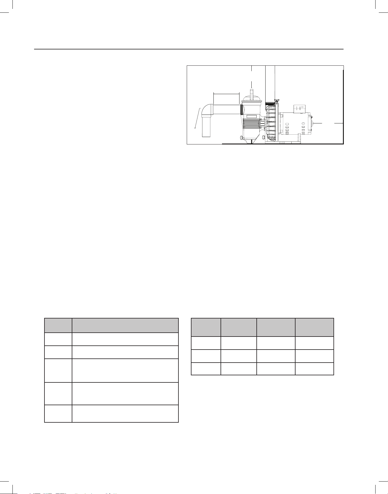
2
Guide d’installation et d’utilisation de la pompe de spécialité WATERFALL™
COUDE
12 PO
(30,5 CM)
MINIMUM
3 PO
(7,6 CM)
MINIMUM
5 x LE DIAMÈTRE DU TUYAU
D’ASPIRATION
INSTALLATION
Emplacement
Assurez-vous que l’emplacement de la pompe de
spécialité Waterfall™ répond aux critères suivants.
Remarque: Ne pas installer cette pompe dans
l’enceinte ou sous la bordure d’un bassin chauffé ou
d’un spa, sauf s’il y a une inscription à cet effet.
1. Installer la pompe aussi près de la piscine ou
du spa que possible. Pour réduire les pertes
d’énergie liées à la friction et augmenter
l’efficacité, employer des tuyaux d’aspiration
courts et directs.
2. Installer l’équipement au moins à 1,5 mètres (5 pi)
de la paroi interne de la piscine ou du spa. Au Canada, l’équipement doit être installé au moins à 3 mètres (9,8 pi)
de l’eau de la piscine.
3. Installer la pompe au moins à 0,9 mètre (3 pi) de la sortie du chauffe-eau.
4. Ne pas installer la pompe à plus de 1,5 mètres (5 pi) au-dessus du niveau de l’eau.
5. Installer la pompe dans un endroit bien ventilé protégé contre l’humidité excessive (c.-à-d., descente de gouttière,
systèmes d’arrosage, etc.).
6. Installer la pompe avec un dégagement d’au moins 7,6 cm (3 po) à l’arrière pour permettre le retrait facile du
moteur pour son entretien et sa réparation. Un dégagement vertical de 30,5 cm (12 po) est requis pour permettre
le retrait du panier-filtre. Voir Figure 1.
Figure 1
Sélection de pompes et de conduites
De nombreuses installations nécessitent une pompe pour monter de l’eau sur plusieurs mètres afin de créer une
chute ou un jeu d’eau de ce type. La montée nécessite de l’énergie et, par conséquent, réduit le débit que peut fournir
la pompe. Consulter le tableau 1 pour voir les estimations de perte de débit.
Il est toujours recommandé de calculer la perte de charge totale du système et de la comparer à la courbe de
rendement de la pompe avant de choisir la taille de la pompe et de la plomberie. Cependant, le tableau 2 peut servir
de guide rapide pour le choix de la taille de la pompe et des conduites pour des installations simples.
Tableau 1 : Effet du changement de hauteur
Changement
de hauteur
Moins de
60 cm (2 pi)
De 60 à 120
cm (2 à 4 pi)
De 1,2 à 3 m
(4 à 10 pi)
De 3 à 4,5 m
(10 à 15 pi)
Plus de
4,5 m (15 pi)
sur le débit
Effet sur le débit
Diminution négligeable du débit si la plomberie respecte
les lignes directrices.
Légère diminution du débit si la plomberie respecte les
lignes directrices.
Le débit est réduit de 50 % à 90 % de son taux maximal,
selon la hauteur exacte et l’installation du système. Il faut
déterminer la perte de charge du système de plomberie
afin d’estimer le débit.
Habituellement non recommandé. Le débit peut être
réduit de 50 % ou moins de son taux nominal maximal.
Cette perte peut être acceptable pour certaines
utilisations à faible débit.
Non recommandé.
Aucun débit possible pour un changement de hauteur
supérieur à 8,1 m (27 pi).
Tableau 2 : Recommandations pour les
dimensions de la plomberie
Modèle de
pompe
AF-75
AFP-75
AF-120
AFP-120
AFP-150
* Le débit nominal maximal est le débit approximatif que la pompe peut évacuer
à travers un court système de conduites dont « la taille convient pour un débit
élevé ». La pompe produira des débits plus faibles si elle doit monter l’eau à une
hauteur plus élevée ou la faire circuler à travers un long système de conduites.
** La taille minimum de plomberie peut être utilisée pour des installations où le
système de plomberie est très court et direct, et compte peu de raccords ou
de coudes. Pour les utilisations où il est important d’atteindre le débit maximal,
toujours utiliser de la plomberie « dont la taille convient pour un débit élevé ».
Débit nominal
maximal*
284 l/min
(75 gal/min)
454 l/min
(120 gal/min)
568 l/ min
(150 gal/min)
Taille minimale**
de la plomberie
3,81 cm (1 1/2 po) 5,08 cm (2 po)
5,08 cm (2 po) 6,35 cm (2 1/2 po)
6,35 cm (2 1/2 po) 7,62 cm (3 po)
Taille de la
plomberie à
débit élevé
Page 43

3
Guide d’installation et d’utilisation de la pompe de spécialité WATERFALL™
ENGLISH
FRANÇAIS
ESPAÑOL
Installation des conduites, raccords et soupapes
1. Utiliser du ruban pour joint fileté ou du mastic d’étanchéité sur tous les raccordements mâles des tuyaux et des
raccords. Utiliser uniquement des mastics d’étanchéité adaptés à la tuyauterie en plastique. NE PAS UTILISER
DE PRODUITS À BASE DE PÉTROLE.
2. Soutenir la tuyauterie pour éviter toute contrainte exercée sur le filtre, la pompe ou les soupapes du système.
3. Lors du raccord à la pompe, appliquer un mastic d’étanchéité sur le filetage, puis serrer à la main, plus 1 ½ tour.
NE PAS SERRER TROP FORT.
4. Les longues sections de tuyauterie et les coudes réduisent le débit. Pour obtenir le meilleur rendement, utiliser le
moins possible de raccords et des tuyaux d’un large diamètre (au moins 3,81 cm [1,5 po]) et placer l’équipement
aussi près que possible de la piscine. Le tuyau d’aspiration de la pompe ne doit pas être d’un diamètre inférieur à
celui du tuyau qui se trouve du côté de l’orifice d’entrée de la pompe.
5. Les raccords d’aspiration doivent être conformes aux normes ASME/ANSI A 112.19.8 M. Utiliser des raccords
d’aspiration doubles.
6. Pour la plupart des installations que Pentair recommande installer une vanne sur les deux l’aspiration de la
pompe et retournent les lignes afin que la pompe peut être isolée au cours de l’entretien de routine. Cependant,
nous recommandons aussi qu’une vanne, un coude ou té installé dans le tuyau d’aspiration doit être au moins à
l’avant de la pompe cinq 5 fois le diamètre de la conduite d’aspiration. Voir Figure 1, à la page précédente.
Exemple : Un tuyau de 3,81 cm (1,5 po) nécessite 19 cm (7,5 po) à l’avant de la bouche d’aspiration de la pompe.
De cette façon, l’amorçage de la pompe sera facilité et durera plus longtemps.
Remarque : N’installez pas de coude à 90 ° directement dans l’entrée de la pompe ou la sortie.
7. La pression de fonctionnement la plus élevée de cette pompe est de 50 psi. Ne JAMAIS faire fonctionner cette
pompe à une pression supérieure à cette pression.
8. Cette pompe n’est PAS conçue pour fonctionner en série avec d’autres pompes.
Page 44

4
Guide d’installation et d’utilisation de la pompe de spécialité WATERFALL™
AVERTISSEMENT
AVERTISSEMENT
AVERTISSEMENT
Vis de mise
à la terre
Fente de l’arbre
du moteur pour
tournevis à tête
plate 3/8 ou 1/2 po
Cosse de
liaison
Prise NPT de
1/2 po pour
connecteur
étanche aux
liquides
Installation des éléments électriques
RISQUE DE CHOC ÉLECTRIQUE OU D’ÉLECTROCUTION. Cette pompe doit être installée par un électricien certifié ou un professionnel qualifié en
respectant le Code national de l’électricité et tous les autres codes et règlements locaux et nationaux en vigueur. Une mauvaise installation est une
source de danger électrique pouvant provoquer des blessures graves, voire la mort, aux utilisateurs, aux installateurs ou autres à la suite d’une décharge
électrique, en plus de poser un risque de dommage matériel.
Débranchez toujours l’alimentation électrique de la pompe au disjoncteur avant son entretien. Le non-respect de cette règle risque de
provoquer des blessures graves, voire la mort, aux utilisateurs, aux personnes responsables de l’entretien ou autres à la suite d’une décharge
Lisez l’ensemble des instructions avant tout entretien de la pompe.
électrique.
Câblage
1. Assurez-vous que tous les disjoncteurs, interrupteurs et
contrôles automatiques sont en position d’arrêt avant de
procéder au câblage du moteur.
CHARGE STOCKÉE – Attendez au moins
60 secondes avant de procéder à l’entretien.
2. Familiarisez-vous avec le schéma de câblage, le nombre de
volts, de hertz et d’ampères ainsi qu’avec la phase de votre
moteur de pompe en particulier. Tous ces renseignements
se trouvent sur la plaque signalétique du moteur située
sur le côté du moteur.
3. Assurez-vous que la tension de l’alimentation est conforme
aux exigences figurant sur la plaque signalétique du moteur.
Des dommages permanents au moteur peuvent se produire
en cas de non-respect de ces exigences.
4. Pour connaître les tailles de câblage et les directives
générales pour l’installation électrique, veuillez suivre les
spécifications définies dans le Code national de l’électricité
et tous les autres codes locaux et nationaux en vigueur.
5. Les moteurs triphasés exigent une protection externe contre
les surcharges. Une inspection initiale est nécessaire pour
assurer la rotation adéquate de la pompe.
Après l’installation, mettez la pompe sous tension quelques
instants, puis mettez-la hors tension. Remarquez la rotation
du ventilateur ou de l’arbre du moteur avant qu’il ne s’arrête.
Si le câblage a été effectué correctement, l’arbre ou le
ventilateur du moteur correspondra à la flèche de rotation
indiquée sur la pompe.
6. Utilisez un protecteur de cordon et veillez à ce que tous les
branchements électriques soient propres et bien serrés.
7. Coupez les fils à la longueur appropriée de façon à ce
qu’ils ne se chevauchent pas ni ne se touchent lorsqu’ils
sont branchés.
Liaison
1. Liez le moteur à la structure conformément au Code national
de l’électricité et à tous les autres codes nationaux et locaux
en vigueur. Utilisez un conducteur de raccordement en cuivre
d’un calibre d’au moins 8 AWG. Au Canada, un conducteur
de raccordement en cuivre d’un calibre d’au moins 6 AWG
est exigé. Faites passer un fil de la vis de la cosse de liaison
externe à la structure de liaison.
2. Branchez le fil de la cosse accessible sur le moteur à toutes les
parties métalliques de la structure de la piscine ou du spa et à
tous les équipements électriques, tous les conduits métalliques
et toute la tuyauterie métallique à moins de 1,52 m (5 pi) des
murs intérieurs de la piscine ou du spa. Faites passer un fil de
la vis de la cosse de liaison externe à la structure de liaison.
Avant de mettre ou remettre la pompe sous tension,
assurez-vous que tous les branchements électriques
sont bien serrés et que les couvercles des compartiments électrique et de
câblage sont correctement installés.
Remarque : Lorsque la pompe est démarrée et arrêtée en la coupant
de la source de courant à l’aide d’un relais ou d’une minuterie, un
dispositif à deux pôles doit être utilisé pour distribuer et couper
le courant aux deux BORNES DE LA LIGNE D’ALIMENTATION.
Pentair propose des disjoncteurs différentiels de fuite à la terre
qui assurent une protection personnelle tout en respectant les
normes du Code national de l’électricité de 2008 à aujourd’hui
pour les pompes pour piscine. Consultez le catalogue de produits
Pentair pour plus de détails.
Figure 2
Mise à la terre
1. Mettez le moteur à la terre de façon permanente à l’aide
de la vis de mise à la terre verte, comme indiqué cidessous. Utilisez le calibre et le type de fil précisés par le
Code national de l’électricité. Assurez-vous que le fil de
mise à la terre est relié à la mise à la terre d’un réseau de
distribution électrique.
2. La pompe doit être raccordée en permanence à un
disjoncteur, à une minuterie ou à un relais à deux pôles.
Remarque : Si l’alimentation c.a. est fournie à l’aide d’un
disjoncteur différentiel de fuite à la terre, la pompe doit être
câblée sur son propre circuit indépendant à moins qu’elle
ne soit utilisée conjointement avec un chlorateur au
sel de Pentair.
Section P/N 350486 Rev. D 4/9/19
Page 45
Guide d’installation et d’utilisation de la pompe de spécialité WATERFALL™
ENGLISH
FRANÇAIS
ESPAÑOL
FONCTIONNEMENT DE LA POMPE
ATTENTION
Démarrage initial
1. Réduire l’ensemble de la pression dans le système et ouvrir tous les purgeurs d’air sur la totalité du circuit
hydraulique avant de mettre en marche la pompe de spécialité Waterfall™. Voir le manuel d’utilisation du
filtre.
2. Vérifier que tous les raccords, les colliers, les couvercles et les accouplements sont bien serrés et conformes
aux recommandations du fabricant de l’équipement.
3. Ouvrir les soupapes d’aspiration et de refoulement pour permettre à l’eau de circuler librement. Sur les
pompes à aspiration submergées équipées d’un panier-filtre, la source d’eau est plus élevée que la pompe.
L’eau coulera dans le panier-filtre et la cuve se remplira d’eau. Sur les pompes à aspiration submergées sans
panier-filtre, l’eau remplit le carter de la pompe.
4. Sur les systèmes à aspiration non submergés, il faut enlever le couvercle de la pompe en le dévissant dans
le sens antihoraire et en le soulevant.
5. Le panier-filtre de la pompe doit être rempli d’eau jusqu’à l’orifice d’aspiration/d’entrée de la pompe.
6. Il est recommandé de graisser le joint torique du couvercle avec du lubrifiant silicone chaque fois que le
couvercle est enlevé. Le joint torique doit être nettoyé et examiné chaque fois que le panier-filtre est ouvert.
7. Remettre le couvercle en place en appuyant sur celui-ci et en le faisant tourner dans le sens horaire.
8. La pompe est maintenant prête à s’amorcer. Mettre en marche le moteur et la pompe s’amorcera. La
durée de l’amorçage dépend de la hauteur d’aspiration, ainsi que de la longueur et du diamètre des tuyaux
d’aspiration. Mettre hors tension la pompe si elle ne s’amorce pas dans les trente (30) minutes et vous
reporter à la section Dépannage à la page 12.
5
NE PAS faire tourner à sec la pompe. Si la pompe tourne à sec, le joint mécanique sera endommagé et la
pompe commencera à fuir. Si cela se produit, le joint endommagé doit être remplacé. TOUJOURS maintenir
un niveau d’eau satisfaisant dans la piscine (à mi-hauteur de l’ouverture de l’écumoire). Si le niveau de l’eau descend audessous de l’ouverture de l’écumoire, la pompe aspirera de l’air à travers l’écumoire, perdant ainsi l’amorce et forçant la pompe
à tourner à sec, ce qui endommagera le joint. Si la pompe fonctionne continuellement de cette façon, une perte de pression
peut se produire, ce qui pourrait endommager le carter, le moteur et le joint de la pompe, et causer des dommages matériels
et des blessures.
Page 46
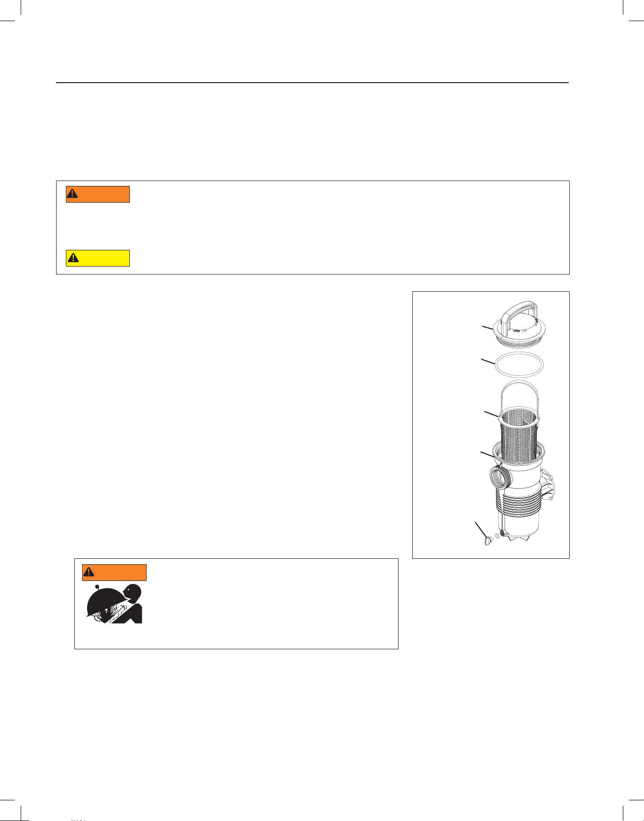
6
Guide d’installation et d’utilisation de la pompe de spécialité WATERFALL™
AVERTISSEMENT
ATTENTION
AVERTISSEMENT
MAINTENANCE
Cette partie décrit comment entretenir la pompe de spécialité Waterfall™.
Nettoyage du panier-filtre de la pompe
Le panier-filtre situé dans la pompe doit être inspecté et nettoyé au moins une fois par semaine. Enlever le couvercle
transparent et le panier, puis le débarrasser des débris qu’il contient. Inspecter le joint torique du couvercle; le
remplacer s’il est endommagé. Le joint de la pompe ne requiert aucune lubrification.
NE PAS ouvrir le panier-filtre si la pompe ne s’amorce pas ou si elle fonctionne sans eau dans la cuve. Les
pompes qui ont fonctionné dans de telles circonstances peuvent présenter une accumulation de pression de
vapeur et peuvent contenir de l’eau bouillante. Le fait d’ouvrir la pompe peut entraîner de graves blessures corporelles. Afin d’éviter
la possibilité de blessures, s’assurer que les valves d’aspiration et de refoulement sont ouvertes et que la température du filtre
est assez basse pour que celui-ci soit touché, puis ouvrir avec une extrême prudence.
Pour éviter d’endommager la pompe et le filtre et pour assurer le bon fonctionnement du système, nettoyer le
filtre de la pompe et les paniers des écumoires régulièrement.
1. Désactiver la pompe au niveau du disjoncteur.
2. Fermer les soupapes d’aspiration et de refoulement.
3. Libérer la pression du système.
4. Tourner le couvercle du panier-filtre dans le sens antihoraire pour le retirer,
puis retirer le panier de la pompe.
5. Retirer les débris du panier-filtre et le rincer. Remplacer le panier si celui-ci
est fendu.
6. Replacer le panier.
7. Remplir la cuve de la pompe et compléter avec de l’eau jusqu’à l’orifice
d’aspiration/d’entrée.
8. Nettoyer le couvercle, le joint torique et la surface d’étanchéité de la cuve.
Remarque : Il est important que le joint torique soit maintenu propre et bien
lubrifié.
9. Réinstaller le couvercle en replaçant celui-ci sur la cuve et en le tournant
dans le sens horaire.
Remarque : Assurez-vous que le joint torique du couvercle est correctement
placé tout autour de la surface d’étanchéité de la cuve.
10. Ouvrir les soupapes d’aspiration et de refoulement.
11. Remettre sous tension la pompe au niveau du disjoncteur.
Couvercle
du filtre
Joint torique
Panier-filtre
Cuve du filtre
Bouchon de
vidange
Figure 3
12. Ouvrir la soupape de décompression manuelle sur le haut du filtre.
13. S’éloigner du filtre. Démarrer la pompe.
14. Laisser l’air s’échapper du filtre jusqu’à ce qu’un jet d’eau continu apparaisse. Fermer la soupape de
CE SYSTÈME FONCTIONNE SOUS HAUTE PRESSION. Quand
toute partie du système de circulation (p. ex., un anneau de serrage,
une pompe, un filtre, une soupape, etc.) est entretenue, de l’air peut
entrer dans le système et devenir pressurisé. L’air comprimé dans le
système peut provoquer une ouverture brusque du couvercle, pouvant
causer la mort, de graves blessures ou des dommages matériels.
Afin d’éviter des dangers potentiels, suivre ces instructions.
décompression manuelle.
Page 47

Guide d’installation et d’utilisation de la pompe de spécialité WATERFALL™
ENGLISH
FRANÇAIS
ESPAÑOL
Préparation à l’hiver
Il revient à vous seul de déterminer s’il est possible que des conditions de gel s’appliquent. Si des conditions de gel
sont prévues, suivre les étapes ci-dessous afin de réduire le risque de dommages causés par le gel. Le bris en cas
de gel n’est pas couvert par la garantie.
Dans les climats doux, si des conditions de gel temporaire sont éprouvées, laisser l’équipement de filtration en
marche toute la nuit pour qu’il ne gèle pas.
Pour éviter les dommages causés par le gel, suivre la procédure ci-dessous :
1. Couper le courant de la pompe au niveau du disjoncteur.
2. Drainer l’eau du carter de la pompe en enlevant les deux bouchons de vidange à visser. Conserver les bouchons
dans le panier de la pompe.
3. Couvrir le moteur pour le protéger contre la pluie, la neige et la glace.
Remarque : NE PAS emballer le moteur dans du plastique ou un autre matériau étanche durant l’entreposage
hivernal. Il est possible de couvrir le moteur pendant une tempête, pour le stockage hivernal, ou pour toute autre
situation, mais jamais lorsqu’il est en marche ou lorsqu’il s’apprête à se mettre en marche.
Entretien du moteur
Protection contre la chaleur
1. Protéger le moteur du soleil.
2. Tous les boîtiers doivent être bien aérés pour éviter les surchauffes.
3. Assurer une ventilation transversale adéquate.
7
Protection contre la saleté
1. Protéger de tout corps étranger.
2. Ne pas entreposer (ni renverser) de produits chimiques sur le moteur ou près de celui-ci.
3. Éviter de balayer de la poussière vers le moteur lorsqu’il est en marche.
4. Un moteur endommagé par de la saleté peut mettre fin à la garantie.
5. Nettoyer le couvercle, la pince, le joint torique et la surface d’étanchéité de la cuve de la pompe.
Protection contre l’humidité
1. Protéger contre les éclaboussures continues ou les pulvérisations d’eau continues.
2. Protéger contre les conditions météorologiques extrêmes telles que les inondations.
3. Si les parties internes du moteur ont été mouillées, le laisser sécher avant de démarrer l’appareil. Ne pas
démarrer la pompe si elle a été inondée.
4. Un moteur endommagé par l’eau peut mettre fin à la garantie.
Remarque :
• NE PAS utiliser du plastique ou un autre matériau étanche pour entreposer la pompe. Il est possible de couvrir
le moteur pendant une tempête, pour le stockage hivernal, ou pour toute autre situation, mais jamais lorsqu’il est
en marche ou lorsqu’il s’apprête à se mettre en marche.
• Lors du remplacement du moteur, s’assurer que le support du moteur est positionné correctement pour
supporter le poids du moteur qui est installé.
Page 48

8
Guide d’installation et d’utilisation de la pompe de spécialité WATERFALL™
AVERTISSEMENT
AVERTISSEMENT
ATTENTION
ENTRETIEN ET RÉPARATIONS
Cette partie décrit comment entretenir la pompe de spécialité Waterfall™.
RISQUE DE DÉCHARGE ÉLECTRIQUE ET D’ÉLECTROCUTION
Cette pompe de piscine doit être installée par un électricien dûment certifié ou autorisé ou un professionnel
en réparation de piscine qualifié, conformément au Code national de l’électricité et à tout code ou à toute
ordonnance applicables de la région. Une installation incorrecte créera une situation de danger électrique qui
pourrait causer la mort ou des blessures graves aux utilisateurs de la piscine, aux installateurs, ou à d’autres,
par décharge électrique, ainsi que des dommages matériels.
Toujours couper l’alimentation de la pompe de la piscine au niveau du disjoncteur avant d’intervenir
sur la pompe. Le non-respect de cette consigne peut engendrer la mort ou des blessures graves au
réparateur, aux utilisateurs de la piscine ou à d’autres personnes par décharge électrique.
Lire toutes les instructions d’entretien avant de travailler sur la pompe.
NE PAS ouvrir le panier-filtre si la pompe ne s’amorce pas ou si elle fonctionne sans eau dans la cuve. Les
pompes qui ont fonctionné dans de telles circonstances peuvent présenter une accumulation de pression de
vapeur et peuvent contenir de l’eau bouillante. Le fait d’ouvrir la pompe peut entraîner de graves blessures
corporelles. Afin d’éviter la possibilité de blessures, s’assurer que les valves d’aspiration et de refoulement
sont ouvertes et que la température du filtre est assez basse pour que celui-ci soit touché, puis ouvrir avec
une extrême prudence.
S’assurer de ne pas rayer ou abîmer les côtés polis de la garniture mécanique; la garniture fuira si ses côtés
sont endommagés.
Démontage de la pompe
Tous les éléments mobiles se trouvent dans le sous-ensemble arrière de cette pompe. Pour voir la liste illustrée des
pièces, consulter Figure 5 à la page 10.
Outils requis :
• Tournevis plat 1/4 po
• Tournevis plat 3/8 ou 1/2 po
• Clé plate 9/16 po
• Maillet en caoutchouc
• Clé anglaise ajustable ou pince de verrouillage
Pour retirer et réparer le sous-ensemble du moteur, suivre les procédures ci-dessous :
1. Fermer les disjoncteurs de la pompe sur le panneau électrique principal. Fermer les soupapes d’aspiration et de
refoulement pour dépressuriser le système.
2. Drainer la pompe en enlevant les bouchons de vidange. Les bouchons de vidange peuvent être retirés à la main.
Aucun outil n’est nécessaire.
3. Desserrer le collier en tournant la molette de serrage dans le sens antihoraire. Le collier de serrage maintient le
sous-ensemble arrière dans le carter (cuve du filtre/volute).
4. Retirer le sous-ensemble arrière du carter (cuve du filtre/volute) et placer le collier de côté.
Remarque : Si le collier ne se détache pas du carter de la pompe et du plateau d’étanchéité lorsqu’il est
desserré, taper légèrement sur le dessus du collier à l’aide d’un maillet en caoutchouc. Cela libérera le collier du
carter.
5. Placer le sous-ensemble arrière à la verticale et sur une surface plate. Utiliser un tournevis plat pour retirer les
trois (3) vis de fixation situées sur le diffuseur.
6. Retirer le diffuseur et sa pièce d’espacement du sous-ensemble arrière.
7. Utiliser le tournevis plat pour retirer la vis de la turbine située au centre de la turbine de la pompe.
Remarque : La vis de la turbine présente un filetage à gauche et se desserre selon le sens horaire.
8. Utiliser un tournevis plat 3/8 ou 1/2 po pour maintenir l’arbre du moteur en place. L’arbre du moteur est accessible
depuis l’arrière de celui-ci.
Remarque : Si le moment de rotation est trop élevé pour maintenir le tournevis à la main, utiliser une clé
ajustable pour maintenir le manche du tournevis en place. Utiliser plutôt des pinces verrouillantes si votre
tournevis possède un manche rond.
Page 49

Guide d’installation et d’utilisation de la pompe de spécialité WATERFALL™
ENGLISH
FRANÇAIS
ESPAÑOL
Démontage de la pompe (suite)
ATTENTION
ATTENTION
9. Dévisser la turbine de l’arbre du moteur en la tournant dans le sens antihoraire.
10. Retirer la partie tournante du joint du ressort à la main.
Remarque : Lorsque vous placez le joint tournant de côté, posez-le TOUJOURS sur sa partie plate. La partie du
joint de ressort rotatif qui entre en contact avec le joint en céramique blanc doit être conservée aussi propre que
possible (poussière, saleté, débris, etc.).
11. Utiliser une clé de 9/16 pouce pour retirer les quatre (4) boulons fixant le moteur au plateau d’étanchéité.
Remplacement du joint d’étanchéité de l’arbre du moteur
La garniture mécanique d’étanchéité peut être remplacée sans débrancher la tuyauterie en retirant le collier de
serrage et en écartant le moteur, l’ensemble de diffuseur à bride de fixation et la turbine du boîtier avant de la pompe.
Le joint de l’arbre est principalement composé de deux parties : un joint de ressort rotatif et un joint en céramique.
Voir Figure 4.
La pompe de spécialité Waterfall™ ne requiert que très peu d’entretien, mais le joint de l’arbre peut s’endommager de
façon occasionnelle, devant ainsi être remplacé.
Les côtés polis du joint peuvent s’abîmer facilement s’ils ne sont pas manipulés avec soin.
Dans les régions au climat tempéré, si des conditions de gel temporaire sont éprouvées, laisser le système de
filtration en marche toute la nuit pour qu’il ne gèle pas.
9
Pour remplacer le joint de la pompe :
12. Suivre les étapes 1 à 11 dans la partie « Démontage de la pompe ».
13. Poser le plateau d’étanchéité à l’envers sur une surface plane et retirer l’ancien joint en céramique.
14. Lubrifiez le siège du joint à l’eau claire.
15. Appuyer le nouveau joint en céramique contre le panneau d’étanchéité avec les pouces et nettoyer la céramique
blanche à l’aide d’un chiffon propre.
16. Utiliser une clé de 9/16 pouce pour remonter le plateau d’étanchéité sur le moteur avec les quatre (4) boulons
fixant le moteur au plateau d’étanchéité.
17. Graisser le filetage de l’arbre du moteur et passer aux étapes 2 à 10 de la partie « Remontage de la pompe »
pour remonter la pompe.
Joint de ressort Joint en céramique
Figure 4
Page 50

10
Guide d’installation et d’utilisation de la pompe de spécialité WATERFALL™
Remontage de la pompe
1. Utiliser la clé de 9/16 pouce pour remonter le plateau d’étanchéité sur le moteur avec les quatre (4) boulons qui
fixent le moteur au plateau d’étanchéité.
2. Repositionner le joint de ressort sur le joint en céramique blanc. S’assurer que le côté en carbone du joint de ressort
est en contact avec le côté en céramique du logement fixe.
3. Graisser le filetage de l’arbre du moteur et visser la turbine sur l’arbre du moteur.
Remarque : Utiliser le tournevis plat 3/8 ou 1/2 po pour maintenir l’arbre du moteur lors du vissage de la turbine.
L’arbre du moteur est accessible depuis l’arrière de celui-ci.
4. À l’aide d’un tournevis plat, visser la vis de fixation de la turbine.
Remarque : La vis de la turbine présente un filetage à gauche et doit être serrée dans le sens antihoraire.
5. Remonter le diffuseur et sa pièce d’espacement en utilisant un tournevis plat et les trois (3) vis du diffuseur.
6. Repositionner le carter de la pompe (cuve du filtre/volute) sur le sous-ensemble arrière.
7. Placer le collier autour du carter de la pompe et du sous-ensemble arrière. Resserrer à l’aide de la molette de serrage.
Remarque : La molette de serrage doit être parallèle au fond du patin de l’équipement lorsque le collier est installé
correctement.
8. Réinstaller les bouchons de vidange. Serrer à la main uniquement!
9. Remplir d’eau le panier-filtre de la pompe.
10. Consulter les procédures de mise en service initiale à la page 5 pour réinitialiser la pompe.
Boîtier de la pompe
Bonde de vidange (2x)
Bouton du
collier de
serrage
Collier de
serrage
Sous-ensemble
Diuseur
Vis de fixation
du diuseur
(3x)
arrière
Vis de
fixation
de la roue
Joint
d’étanchéité
Entretoise
du
diuseur
Plaque
d’étanchéité
Moteur
Vis de fixation du
moteur à la plaque
d’étanchéité (4x)
Figure 5
Page 51

11
Guide d’installation et d’utilisation de la pompe de spécialité WATERFALL™
ENGLISH
FRANÇAIS
ESPAÑOL
ATTENTION
INSTRUCTIONS DE REDÉMARRAGE
Si la pompe de spécialité Waterfall™ est installée sous le niveau de l’eau de la piscine, fermer les soupapes de retour
et d’aspiration avant d’ouvrir la cuve à cheveux et à peluches de la pompe. S’assurer de rouvrir les soupapes avant de
remettre en fonction la pompe.
NE PAS faire tourner à sec la pompe. Si la pompe tourne à sec, le joint mécanique sera endommagé et la
pompe commencera à fuir. Si cela se produit, le joint endommagé doit être remplacé. TOUJOURS maintenir un
niveau d’eau satisfaisant dans la piscine (à mi-hauteur de l’ouverture de l’écumoire). Si le niveau de l’eau descend au-dessous de
l’ouverture de l’écumoire, la pompe aspirera de l’air à travers l’écumoire, perdant ainsi l’amorce et forçant la pompe à tourner à
sec, ce qui endommagera le joint. Si la pompe fonctionne continuellement de cette façon, une perte de pression peut se produire,
ce qui pourrait endommager le carter, le moteur et le joint de la pompe, et causer des dommages matériels et des blessures.
Amorçage de la pompe
Le panier-filtre de la pompe doit être rempli d’eau avant le premier démarrage de la pompe. Suivre ces étapes pour
amorcer la pompe :
1. Retirer le couvercle de la pompe.
2. Remplir la cuve du panier-filtre avec de l’eau.
3. Réinstaller le couvercle de la pompe sur la cuve. La pompe est désormais prête à s’amorcer.
4. Ouvrir la soupape d’échappement d’air du filtre et s’éloigner du filtre.
5. Activer l’interrupteur ou la minuterie.
6. Lorsque l’eau déborde de la soupape d’évacuation de l’air, fermer la soupape. Le système ne devrait alors plus
contenir d’air et devrait refaire circuler l’eau vers la piscine et depuis celle-ci.
7. Cette pompe s’amorcera dans les trente (30) minutes. Ne pas laisser la pompe fonctionner plus longtemps sans
développer un débit constant. Si la pompe ne s’amorce pas, voir la partie « Dépannage » à la page 12.
8. Les pompes à deux vitesses doivent fonctionner à haute vitesse pour l’amorçage.
Page 52

12
Guide d’installation et d’utilisation de la pompe de spécialité WATERFALL™
AVERTISSEMENT
DÉPANNAGE
Utiliser l’information de dépannage suivante pour résoudre les problèmes potentiels de la pompe de spécialité
Waterfall™.
RISQUE DE DÉCHARGE ÉLECTRIQUE OU D’ÉLECTROCUTION. Une installation incorrecte
constitue un danger électrique qui pourrait causer la mort ou des blessures graves pour les
utilisateurs, les installateurs ou toute autre personne en cas de décharge électrique, ainsi que des
dommages matériels.
1. Si vous n’êtes pas habitué au système de filtration ou de chauffage de votre piscine :
a. NE PAS tenter d’ajustement ou d’entretien sans consulter votre concessionnaire ou
un professionnel qualifié en entretien de piscines.
b. Lire le guide d’installation et d’utilisation en totalité avant de tenter d’utiliser, de réparer
ou d’ajuster le système de filtration ou de chauffage de la piscine.
2. COUPER L’ALIMENTATION de la pompe au niveau du disjoncteur avant de procéder à
l’entretien ou à la réparation.
Problèmes et mesures correctives
Problème Cause Solution
La pompe ne s’amorce pas 1. Il n’y a pas d’eau dans le panier-filtre. Ajouter de l’eau dans la cuve.
2. Le couvercle du panier-filtre n’est pas assez serré. Resserrer le couvercle.
3. Joint torique endommagé. Remplacer le joint torique.
4. Le niveau d’eau se situe en dessous de l’écumoire. Ajuster le niveau d’eau de la piscine.
5. Le panier-filtre ou l’écumoire est obstrué. Vider le panier.
6. Soupape fermée sur le système de tuyauterie. Vérifier l’ensemble des soupapes et
ouvrir toutes les soupapes nécessaires.
7. La pompe fonctionne à faible vitesse (appareil Ajuster à une vitesse supérieure.
à deux vitesses seulement).
8. Fuite d’air dans le conduit d’aspiration. Trouver et réparer la fuite.
Débit faible 1. Obstruction dans le conduit de retour. Libérer le conduit de retour de
l’obstruction.
2. Le panier-filtre ou l’écumoire est obstrué. Nettoyer le panier.
3. La turbine est bloquée. Dégager les obstructions.
4. Fuite d’air dans le conduit d’aspiration. Trouver et réparer la fuite.
5. Il y a une obstruction dans le conduit d’aspiration. Trouver et retirer l’obstruction.
Le moteur ne démarre pas 1. L’interrupteur d’alimentation est fermé. Vérifier l’interrupteur d’alimentation et
réinitialiser.
2. Le disjoncteur s’est déclenché. Vérifier le disjoncteur et réinitialiser. Si
cela se reproduit, contacter un
électricien.
3. La pompe est en mode « éteint » sur un circuit Vérifier le mode minuterie.
contrôlé par minuterie.
4. Les raccords électriques du moteur sont incorrects. Faire vérifier les raccords électriques
par un électricien.
5. L’arbre du moteur est immobilisé par des Faire remplacer les roulements du
roulements moteur ou remplacer la pompe. endommagés.
6. La turbine est immobilisée par des débris. Nettoyer la turbine.
Le moteur surchauffe 1. Les branchements à l’alimentation électrique sont Faire vérifier les raccords électriques
incorrects. par un électricien.
2. Les fils de la pompe sont d’un calibre insuffisant. Consulter un électricien pour refaire le
câblage électrique de la pompe.
3. La dispensation d’électricité par le fournisseur Aviser le fournisseur d’électricité.
d’électricité estaible.
4. Aération inadéquate du moteur. Retirer toute entrave à la ventilation.
Page 53
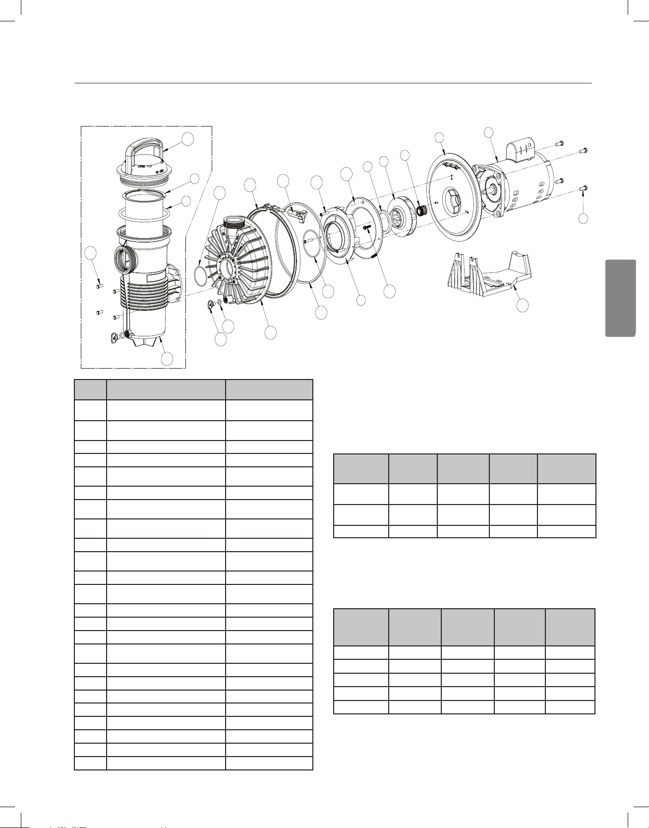
13
Guide d’installation et d’utilisation de la pompe de spécialité WATERFALL™
ENGLISH
FRANÇAIS
ESPAÑOL
1
2
4
5
6
12
11
13
7
15
18
14
17
19
20
21
16
3
23
8
10
24
9
22
ENSEMBLE DU BOÎTIER POUR
LES MODÈLES AFP-75, 120, 150
UNIQUEMENT
PIÈCES DE RECHANGE
Nº
D’ARTICLE
1
2
3
4
5
6
7
8
9
10
Joint torique du couvercle
11
12
13
14
15
16
17
18
19
20
21
22
23
24
Vis de fixation de la roue
Joint torique du diffuseur
Joint torique de la plaque d’étanchéité
Bouton du collier de serrage
Joint torique du bouchon de vidange (2x)
Bouchon de vidange (2x)
Joint torique du boîtier avant
Boulon du boîtier de crépine (4x)
DESCRIPTION
Moteur
Plaque d’étanchéité
Boulon du moteur (4x)
Joint d’étanchéité
Roue
Roulement avant
Diffuseur
Panier de filtration
Couvercle
Entretoise du diffuseur
Vis du diffuseur (3x)
Boîtier
Collier de serrage
Base
Boîtier de crépine
NUMÉRO
DE PIÈCE
Consulter le tableau du
moteur
Consulter le tableau de la
crépine
070429
354545S
Consulter le tableau du
moteur
355142
Consulter le tableau du
moteur
Consulter le tableau de la
crépine
350013
Consulter le tableau de la
crépine
355389
Consulter le tableau du
moteur
355141
355227
355329
Consulter le tableau de la
crépine
354629
175025
355305
192115
357161
355330
355300
354265
Tableau du moteur
Modèle
AFP-75,
AF-75
AFP-120,
AF-120
AFP-150 356075** 355220 355140 355495
Moteur
(article no 2)
356076* 355544 355545 355317
356076* 355068 355069 355495
Roue
(article no 5)
Diffuseur
(article no 7)
(*) - Remplacé N/P 355218 après mai 2019
(**) - Remplacé N/P 355222 après mai 2019
Tableau de la crépine
Modèle
AFP-75
AFP-120
AFP-150
AF-75
AF-120
Plaque
d’étanchéité
(article no 2)
355303 355387 355301 355468
355497 355387 355301 355468
355497 355441 355300 355468
355303 - - 355302
355497 - - 355302
Panier de
filtration
(article no 8)
Couvercle
(article no 10)
Entretoise du
diffuseur
(article no 12)
Boîtier
(article no 16)
Page 54

NOTES / NOTAS / REMARQUES
Page 55

NOTES / NOTAS / REMARQUES
Page 56

1620 HAWKINS AVE., SANFORD, NC 27330 • (919) 566-8000
*355143*
10951 WEST LOS ANGELES AVE., MOORPARK, CA 93021 • (805) 553-5000
WWW.PENTAIR.COM
Toutes les marques de commerce et tous les logos Pentair sont la propriété de Pentair ou de l’une de ses liales internationales. Waterfall™ sont des
marques déposées de Pentair Water Pool and Spa, Inc. ou de ses sociétés aliées aux États-Unis ou dans d’autres pays. Sauf indication expressément
contraire, les noms et les marques de tiers qui peuvent être utilisés dans le présent document ne sont pas utilisés pour indiquer une aliation ou une
approbation entre les propriétaires de ces marques et Pentair Water Pool and Spa, Inc. Ces noms et ces marques peuvent être des marques de commerce
ou des marques déposées de ces tiers. Parce que nous améliorons constamment nos produits, Pentair se réserve le droit de changer ses caractéristiques
sans avis préalable. Pentair offre l’égalité d’accès à l’emploi.
©2019 Pentair Water Pool and Spa, Inc. Tous droits réservés. Ce document peut être modié sans avis préalable.
P/N 355143 REV. D 5/17/19
 Loading...