

Page 1
TM
Smart pH
W
a
t
er
C
h
e
m
is
try
C
o
n
trolle
r
I
N
T
E
L
L
I
G
E
N
C
E
I
N
S
I
D
E
A
C
U
-
T
R
O
L
I
N
S
I
D
E
w
w
w
.a
cu
-
tr
o
l.co
m
M
ad
e in
U
S
A
11
0
VAC,
5A
D
is
c
onne
c
t
p
ow
er
s
ource
befo
r
e serv
i
cing uni
t
T
u
r
n
“
S
e
t
P
o
in
t
”
k
n
o
b
t
o
t
h
e
f
a
r
left
o
r
r
ig
h
t
to
t
r
ig
g
e
r
p
H
r
e
a
d
in
g
f
u
n
c
t
i
o
n
(
s
e
e
m
a
n
u
a
l
f
or
d
e
ta
i
ls
)
P
O
W
E
R
H
IG
H
BA
LA
NC
ED
O
W
C
HE
M
IC
A
L
FEED
pH
pH
p
H
S
e
t
P
o
in
t
cu-T
rol
P
R
O
G
R
A
M
M
A
B
L
E
C
O
N
T
R
O
L
L
E
R
S
®
S
MART pH
INSTALLATION
GUIDE
1-800-273-4667 • 530-823-9898
11830 Kemper Road
Auburn, CA 95603
Fax: 530-823-9899
www.acu-trol.com
www.pentairwater.com
Page 2

Page 3
1.1 IMPORTANT SAFETY INFORMATION
!
PLEASE READ THIS USER MANUAL completely before installing or operating the equipment. The Smart
pHTM is a Class 1 product for protection against electric shock and a Type 1 product with regards to disconnection of
the control circuits.
Observe the following safety precautions:
Do not permit anyone untrained or under the age of 18 to use this product.
Unit must be properly connected to earth ground.
Never apply power when front panel is not secured in the closed position.
Never service unit with power applied, always turn OFF main circuit breaker to unit and all
equipment when servicing.
Touching the controller’s internal parts could result in injury and or damage to the controller. In case of a
malfunction, only a qualified technician should repair the controller.
Risk of Electric Shock. Connect only to a grounding type receptacle protected by a ground-fault circuit
interrupter (GFCI).
Do not bury cord. Route cord to eliminate abuse from heater exhaust, lawn mowers, hedge
trimmers, and other equipment.
Be careful not to damage any of the insulation on wires or the power cord. Should the cord be damaged
return it to your dealer for a replacement. Continued use could result in fire or electric shock.
To reduce the risk of electric shock, do not use an extension cord to connect unit to electric supply;
provide a properly located GFCI.
Never remove or install any cables between the circuit cards when power is applied, damage to the
components may occur.
WARNING
CHEMICAL BURN HAZARD - Make sure pumps are OFF before drilling into pipes. Securely fasten all
electrical, water and chemical lines. Locate chemical feed pumps and chemical storage tanks in a safe and secure area.
Never turn chemical feed pumps ON when any valves are closed. The feed lines can blow off and spray full strength
chemicals causeing damage to property and cause serious injury or death.
WARRANTY
Acu-Trol, Inc. warrants the Smart pHTM to be free from defects in manufacturing and workmanship for a period of
ONE (1) YEAR from the date of manufacture for the electronic module. All sensors and flow cells have a ONE (1)
YEAR from the date of manufacture. Other equipment is covered by the individual manufacturer’s own warranty.
During the warranty period, any defective parts will be repaired or replaced when necessary by Acu-Trol, Inc.
This warranty does not cover: (a) the buyers’ labor or any servicing fees related to replacement of the Product; (b)
damage resulting from the use of this Product in other than its normal manner; (c) damage from misuse, accident or
neglect; (d) damage from improper testing, operation, or installation; (e) not operating the Product on a dedicated
(separate) circuit or under conditions other than those recommended or at voltages or amperages other than the
voltage or amperage indicated on the Product; and (f) acts of Mother Nature (i.e. lightning, electrical storms, floods,
etc.). In addition, attempting to service or modify the Product will render this Warranty Void. Defective parts should
be returned immediately to the local Acu-Trol dealer, any parts returned to the factory require a return of material
authorization code to subsequently generate an RMA (Return Material Authorization form). An Acu-Trol Technician
will analyze the returned part and determine the cause of failure and process accordingly.
WARRANTY CARD MUST BE COMPLETED AND RETURNED AT ONCE TO BE KEPT ON FILE
Smart pH 3
Page 4
1.4 SMART PHTM OVERVIEW
Smart pH
Wa
ter Chemistry Co
n
trolle
r
I
N
T
E
L
L
I
G
E
N
C
E
I
N
S
I
D
E
A
C
U
-
T
R
O
L
I
N
S
I
D
E
w
ww
.a
c
u
t
r
o
l
.c
o
m
M
a
d
e
in
U
S
A
1
1
0
V
A
C
,
5
A
D
is
c
o
n
n
e
c
t
p
o
w
e
r
s
ou
r
c
e
be
f
o
r
e
s
e
r
v
ic
in
g
u
ni
t
T
u
r
n
“
S
e
t
P
o
i
n
t
”
k
n
o
b
t
o
t
h
e
f
a
r
l
e
f
t
o
r
r
i
g
h
t
t
o
t
r
i
g
g
e
r
p
H
r
e
a
d
i
n
g
f
u
n
c
t
i
o
n
(
s
e
e
m
a
n
u
a
l
f
o
r
d
e
t
a
i
l
s
)
POWER
HIGH
B
A
L
A
N
C
E
D
OW
CHEM
ICAL
FE
E
D
p
H
p
H
pH
S
e
t
P
o
i
n
t
cu-T
ro
l
P
R
O
G
R
A
M
M
A
B
L
E
C
O
N
T
R
O
L
L
E
R
S
®
SUMMARY: The Smart pH is a microprocessor based, modular automation system capable of
continuous local monitoring and control of the pH water chemistry for pool and spa
applications. The Smart pH will maintain the pH levels (either increasing pH using base
or decreasing pH using acid) of your water system automatically. The Smart pH will
only increase or decrease the pH. The Smart pH is recommended for use with a
chlorine generator or an erosion type feeder. You can also use the Smart pH when hand
feeding liquid chlorine (base) or muratic acid as the chlorine will increase the pH and
the acid will decrease the pH. The Smart pH can also control CO2 gas systems with the
same efficiency as an acid feed controller. (For specific information on installation refer
to documentation supplied with CO2 chemical feeder).
RELAY: The Smart pH has one relay module to control the pH levels.
SENSORS: The Smart pH can measure inputs from one pH sensor.
VOLTAGE: The Smart pH can only work on an input voltage of 110 VAC.
CHAPTER 2, INSTALLATION
2.1 PREPARATION
Receipt Inspection: Upon receiving the controller from shipping, check the carton carefully. Report any damaged items directly to the shipping company. Examine the package content list below and verify that all items are
present. Please contact your local Acu-Trol dealer if any items are missing or have been damaged. Use care when
unpacking equipment to avoid damage or loss of small parts.
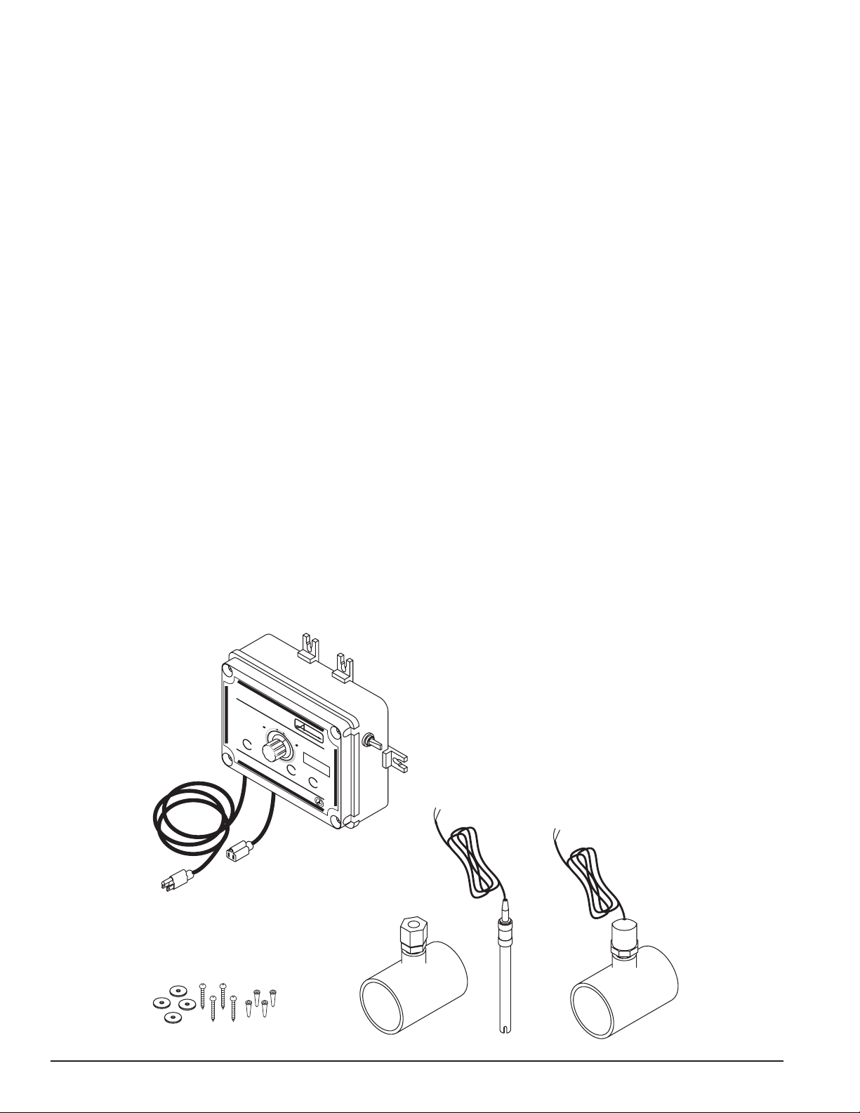
2.2 PACKAGE CONTENTS
1. Smart pH Controller
2. Mounting Hardware
3. pH Sensor "T" Assembly
4. pH Sensor
5. Flow Switch Assembly
4
5
Smart pH 4
Page 5

INSTALLATION SUMMARY
!
1. Identify new and existing equipment to be connected.
2. All controlled equipment must be 110 VAC (see Section 2.5.2)
3. Mount the Smart pH away from direct sunlight and on a flat vertical surface.
4. Connect the supply voltage with main breaker off (must be a separate dedicated circuit GFCI).
CAUTION
Keep the Smart pH out of direct sunlight or inside a room if possible.
MOUNTING THE SMART PH
TM
Select a location for mounting the Smart pH that will meet the following recommendations.
1. At least ten (10) feet from open water.
2. Close enough for the supplied power cord (6') to reach the supply voltage. The controller will not operate
properly without a solid earth ground connection.
3. Supply power must be routed to the Smart pH in accordance with all national, state, and local codes.
4. Keep the Smart pH out of direct sunlight and inside a room if possible, a shade screen should be
used for outdoor installations.
5. The installation surface must be solid and vertical. Do not mount the controller in a horizontal position.
6. Maintain adequate clearance for opening the enclosure.
7. The environment should be free of chemical fumes and excessive heat.
8. Mount as far as possible from sources of electrical interference.
9. Hold the controller against the mounting surface with a closed lid and mark the location of the mounting
brackets on the wall. Prepare holes as necessary and secure controller using hardware provided.
10. Make sure the controller box is not distorted by an uneven mounting surface.
1.85"
Figure 1. Mounting Dimensions
Proper and safe operation requires an earth ground connection. All electrical work must be performed by a licensed electrican and must conform to all national, state, and local codes.
3.30"
8.3"
WARNING
Smart pH 5
Page 6

ELECTRICAL SPECIFICATIONS
GND
NOB
NOW
The following electrical specifications tabled below must not be exceeded.
ITEM DESCRIPTION LIMIT
Input Voltage Maximum Input AC Voltage 125 VAC
Input Current Maximum Input Current 5 AMPS (AC)
Input current Maximum Current for Single Relay 5 AMPS (AC)
Temperature Minimum/Maximum Operating Temperature 30° - 110° F
Standby Current Current with Relay OFF, LED ON
Current with Relay OFF, LED OFF
Sensor Range pH 4.22 - 9.78
CONNECTING THE 110VAC POWER SUPPLY
For cord connected installations wait to plug the cord in as the last step in the installation. For hard-wired installations make sure the circuit breaker is off and turn it on as the last step in the installation.
having a licensed electrician perform the installation to ensure all national, state, and local codes are met.
RELAY BOARD CONTROL VOLTAGE SETTING
The relay comes set from the factory for 110 VAC control voltage. Changing the jumper on the relay will allow
for different control voltages of 24V or for a Dry Contact Switch (see Fig. 2)
50 mA (AC) Typical
30 mA (AC) Typical
Acu-Trol recommends
Factory Setting
24 VAC
Dry Contact
Switch
Figure 2. Relay Jumper Settings
CHEMICAL FEED PUMP LOCATION
If the feed pump has not been previously installed, follow the instructions included with the chemical feed
pump. Some chemical feed pumps include a power cord and are ready to plug in. If a "pigtail" has been ordered with
the Smart pH, simply plug the pump power cord into the "pigtail". If a "pigtail" is not installed the power cord from
the pump will need to be modified. The list below provides overall installation recommendations:
1. Mount at least 10 feet from open water.
2. Install the pump below the level of the Smart pH and away from any other equipment or systems.
3. Install close enough to the Smart pH for the feed pump power cords to reach.
4. If a plug is already on the pump, simply plug in the pump to the Smart pH "pigtail". If
pigtails are not installed, you will need to hardwire the pump to the Smart pH relay board.
5. Route the supply power wires to the Smart pH through the lower fitting and attach to the appropriate
relay terminals on the relay circuit board (see Section 5, "Wiring Diagram). If the wire ends were striped
and not ferruled make sure that no frays of wire are out of the connector as this may lead to a short.
6. PVC conduit can also be used (in accordance with all national, state, and local codes).
7. When installing metal conduit into the controller, a ground LUG should be used (in accordance with all
national, state, and local codes) to connect the conduit to the relay board ground.
Smart pH 6
Page 7

PLUMBING INSTALLATION
Smart pH
Water Chemistry Controller
I
N
T
E
L
L
I
G
E
N
C
E
I
N
S
I
D
E
A
C
U
-
T
R
O
L
I
N
S
I
D
E
www.acu-trol.com Made in USA 110 VAC, 5A
Disconnect power source before servicing unit
Turn “Set Point” knob to the
far left or right to trigger pH
reading functio
n
(see manual for details)
POWER
HIGH
BALANCED
LOW
CHEMICAL
FEED
pH
pH
pH
Set Point
cu-Trol
PROGRAMMABLE CONTROLLERS
®
Install the flow sensor and the pH sensor using the following steps:
1. Turn off all power to the system, close all isolation valves and then release any air from the
system by turning the release valve on top of the system filter.
2. The flow sensor and pH sensor "T's" must be installed after the filter but, before the chemical injector
Install the flow sensor before the pH sensor. The flow sensor "T" has an arrow on it. The arrow
indicates water flow direction.
3. Remove the protective cap from the pH sensor. Using the "T" with the sensor adapter, install the sensor
into the adapter. Push the sensor into the adapter until it hits the bottom of the "T"
(see Fig 5). Tighten the sensor adapter (hand tighten only).
4. Allow for sufficient drying time of the PVC glue (minimum recommendation of 24 hrs).
5. Close the air release valve on top of the filter. Open any isolation valves and check the system for leaks.
CAUTION
The flow switch and the pH sensor must be installed before the
chemical injectors. Installing the
flow switch and pH sensor after the
chemical injectors will cause the
Smart pH to give false readings.
SMART pH
CHEMICAL
FEEDER PUMP
PUMP
Figure 3. Plumbing Installation Diagram
WATER
FLOW
FILTER
HEATER
pH
Sensor
PUSH SENSOR
INTO "T" UNTIL
IT STOPS
FLOW SENSOR "T" MUST BE
INSTALLED IN THIS DIRECTION
Figure 4. Flow Sensor Installation
PVC "T"
Figure 5. pH Sensor Installation
Smart pH 7
Page 8

SENSOR WIRING
pH SENSOR
Open front panel by removing the top two screws completely and unscrewing the lower two screws about half
way. The front cover will now fold down like a shelf for easy access to the wiring connections and dipswitches.
Route the sensor wires through the small strain relief into the Smart pH and to the appropriate connectors
(green terminal bar) in the Smart pH (see Fig. 6).
The polarity (+ and -) of the pH sensor must be observed. The pH sensor wire (+) is clear, and the pH sensor
wire (-) is green. Leave excess wire outside the controller enclosure. Do not stuff excess wire inside the
controller as this may cause excess strain on sensor and relay connections. Do not cut the sensor wire. If the
cable is longer than needed, it should be coiled neatly and attached under the controller enclosure.
WARNING
Sensors are shipped with a protective cap covering the electrode tip to protect the sensing element. Sensors should be
kept in the protective cap until ready for installation, if the cotton in the protective cap becomes dry, wet it with tap
water. During shipment, air bubbles may have entered the electrode, carefully shake the electrode downward (like a
thermometer) to dispel the air from the sensing elements inside the electrode. Before using the sensor, remove the cap.
INSIDE
THE
FLOW
Figure 6. Smart pH Sensor and Flow Switch Wiring
pH
FLOW SENSOR
The flow sensor is used to indicate that there is flow and that it is OK to feed chemicals . The Smart pH will not
allow chemicals to feed if the water flow is not on and detected.
Route the sensor wires through the small strain relief into the Smart pH and to the appropriate connectors
(green terminal bar) in the Smart pH (see Fig. 5).
Do not stuff excess wire inside the controller as this may cause excess strain on sensor and relay connections.
Do not cut the sensor wires.
If the cable is longer than needed, it should be coiled neatly and attached under the controller enclosure.
Smart pH 8
Page 9

2.9 SETTING THE DIP SWITCHES
1
2
3
4
5
6
OPEN
1. Set the switches on the DIP Switch as to your requirements. (See fig 7.)
SWITCH Up Down
1 Acid Feed Base Feed
2 No Overfeed Limit 1 hr. Overfeed Limit
3 Do not change Do not change
4 Proportional Off Proportional On, 5%
of Set Point
5 1 Min. Cycle Time 3 Min. Cycle Time
DIP SWITCHES IN THE DOWN POSITION
(FACTORY SETTING)
Figure 7. DIP Switch Settings
6 5% of the Cycle
Time.
Descriptions:
Acid Feed: DIP Switch 1 (up) will turn on the chemical feeder when the "High" LED side is on.
OR
Base Feed: DIP Switch 1 (down) will turn on the chemical feeder when the "Low" LED side is on.
Overfeed: The unit will enter overfeed mode when the feed time has exceeded the setting of DIP
Switch 2. When in overfeed mode, the Low, Neutral, and High LED’s will flash.
Proportional: DIP Switch 4 will set a variable time length calculated to turn the chemical feeders on
and off so that the pH level does not overshoot.
Cycle Time: Use DIP Switch 5 to have a one (1) minute cycle time (up) or a three (3) minute cycle
time. The On Time + Off Time = Cycle Time.
On time: Dip Switch 6 determines whether the chemical feeder can be on for 5% of the On Time or
whether it is 20% of the On Time (This can help the unit from overfeeding on small bodies of
water or spas).
20% of the Cycle
Time.
FINISHING AND TESTING
Once the controller system has been installed with applicable sensors and modules, allow the Smart pH system
to acclimate to the body of water for 24 hours.
1. After all wire connections are complete, close the panel and tighten the enclosure screws.
2. Turn on the main breaker and turn on the Smart pH.
3. Verify that the controller is active and that LED’s are working.
OPERATIONS
SMART PH
When the pH level is .2 or greater above the set point the HIGH LED will be on.
When the pH level is .2 or greater below the set point the LOW LED will be on
When the pH level is .05 to .2 above the set point the HIGH LED and the BALANCED LED will be on.
When the pH level is between +/- .05 from the set point the BALANCED LED will be on.
When the pH level is .05 to .2 below the set point the LOW LED and BALANCED LED will be on.
TM
BASIC OPERATION
Smart pH 9
Page 10

Smart pH
Water Chemistry Controller
I
N
T
E
L
L
I
G
E
N
C
E
I
N
S
I
D
E
A
C
U
-
T
R
O
L
I
N
S
I
D
E
www.acu-trol.com Made in USA 110 VAC, 5A
Disconnect power source before servicing unit
Turn “Set Point” knob to the
far left or right to trigger pH
reading function
(see manual for details)
POWER
HIGH
BALANCED
LOW
CHEMICAL
FEED
pH
pH
pH
Set Point
cu-Trol
PROGRAMMABLE CONTROLLERS
®
POWER Indicator
Indicates when power is
provided to the unit
CHEMICAL FEED
Indicator
lights green, indicating
that chemicals are
flowing
HIGH Indicator
lights red, indicating
system pH is high
LOW Indicator
lights red, indicating
pH is low
BALANCED Indicator
lights green, indicating
set point has been
reached
Figure 6. Smart pH Basic Operation
STARTUP
SETTING pH
Measure the pH using a standard test kit. If not already done, close up the front cover of the Smart pH. When the
knob (potentiometer) is turned all the way to the right or left the units Low, Balanced, and High LED’s will begin to
flash simultaneously. Count the number of flashes on each LED. This will be the reading of the pH probe being monitored. For example, for a pH reading of 6.23 the Low LED will flash 6 times, the Neutral LED will flash 2 times and
the High LED will flash 3 times. The LED’s will all go off for approximately 2 seconds and then restart again until the
knob is moved back into the set point range. Chemical feeding will stop when the Smart pH detects there is no flow.
See Chapter 6, "Setup Check Out Sheets" for help with start up. The Smart pH is not an absolute measuring device. If the pH of the system is too high turn the knob to the left and monitor over some period of time. If the pH is too
low turn the knob to the right and then monitor over time. Monitor the ph readings by using the hand check method
and adjust the Smart pH to achieve the desired reading. Normally the probes should read +/- .5 of the hand check, if
out of this range the probe may need to be cleaned (See "Cleaning Probe", Section 4.2).
TROUBLESHOOTING
PART PROBLEM SOLUTION #1 SOLUTION #2
pH Levels High pH won't come down
even after turning control
down
pH Sensor Reading never matching
pH Sensor Readings never matching
Flow Switch Not working Check continuity when flow
hand check
hand check
LED's Flashing Overfeed alarm ON 1 hour or none only Make sure feeder is working
Smart pH 10
Check chemical tank and
make sure it is not empty
Clean sensor, check ground
on input power
Short (+) (-) on sensor,
pH = 7.0. Remove sensor
is present
Check power connection
between the Smart pH and
the chemical controller
Check total alkalinity
Sensor may need to be
cleaned
properly
Page 11

DIAGRAMS
120VAC SUPPLY POWER WIRING
TO
120VAC
SUPPLY
POWER
PIGTAIL TO
CHEMICAL
FEEDER PUMP
(120VAC)
Smart pH 11
Page 12

EXPLODED VIEW
3
5
2
4
(4)
4A
PARTS LIST
Dia. # Description Part #
1 Knob with O-Ring ...............................................................................................754000030
2 Top Half Replacement, Complete .......................................................................714000030
3 Relay Module ......................................................................................................714000050
4 Bottom Half Replacement, Complete .................................................................714000040
4A Cables, (1) Power Cable, 6' and (1) Pigtail, blue, 6" ...........................................754000020
4B Mounting Feet (4) with Screws (4) .....................................................................715000000
5 Sensor, pH ...........................................................................................................744000020
6 Sensor, Flow Switch ............................................................................................744000030
6
Smart pH 12
Page 13

400000360 REV. A 6/11/2007 For Technical Support Call 800-273-
Acu-Trol, Inc.
11830 Kemper Road
Auburn, CA 95603
 Loading...