

Page 1

Index
1. GENERAL INFORMATION
1.1 Supplied documents
1.1.1 Manual
1.2 Information ownership
1.3 Machine identification data
1.4 EC declaration of conformity
1.5 General information on safety
1.5.1 Personnel qualification
1.5.2 Special compliance
1.6 Conventions
1.6.1 Word conventions
1.6.2 Typographical conventions
1.7 Expected uses
1.7.1 Expected uses
1.7.2 Expected modes of installation
1.8 Non expected uses
1.8.1 Liabilities resulting from non expected uses
1.9 Warranty
1.10 Service
1.11 How to use the supplied documents
2. DESCRIPTION
2.1 Description
2.1.1 Architecture and operating principles
2.1.2 Machine structure
2.2 Technical features
2.2.1 Noise
2.2.2 Liability
page 14
page 16
3. INSTALLATION
3.1 Hoisting
3.1.1 Machine free from any type of packaging
3.1.2 Machine packed in cardboard box
3.1.3 Machine packed in a wooden crate
3.1.4 Machines secured on a supporting surface
3.2 Transport
3.3 Storage
3.3.1 Characteristics of the storage area
3.3.2 Environmental characteristics of the storage area
3.4 Preliminary checks
3.4.1 Check for damages
3.4.2 Damage signalling
3.5 Preparation of the installation area
3.5.1 Characteristics of the installation area
3.6 Installation
3.6.1 Connection to piping
3.6.2 Terminal box position
3.6.3 Connection to the electric system
3.7 Adjustment
3.7.1 Machine motor coupling adjustment
4. USE
4.1 Priming
4.1.1 Machines installed under head
4.1.2 Machines installed above head (suction mode)
4.2 Starting
4.3 Start and stop frequency control
page 17
page 21
5. MAINTENANCE
5.1 Lubrication
5.2 Temporarily quiescing
5.3 Periodical inspection
5.4 Extraordinary maintenance
6. OPERATION TROUBLES
7. DISMANTLING
7.1 Disconnecting the machine
7.2 Residual risks after disconnection
page 22
page 23
page 24
13
Page 2
1. GENERAL INFORMATION
1.1 Supplied documents
1.1.1 Manual
Data
Instruction manual
Issue 1
Version 1105
Code 253P7530
Recipients
This manual is dedicated to the operators charged of the
machine management during all the phases of its technical life
Contents
This manual includes the following information:
- Manufacturer declaration
- Information on safety
- Sales information
- Information on documents
- Machine description
- Transport information
- Storage information
- Installation information
- Adjustment information
- Use information
- Maintenance information
- Dismantling information
These pieces of information are subdivided into the following
chapters and appendixes of this manual:
Chapter 1 : General information
Chapter 2 : Description
Chapter 3 : Installation
Chapter 4 : Use
Chapter 5 : Maintenance
Chapter 6 : Operating troubles
Chapter 7 : Dismantling
Appendix : Product specification
1.2 Information ownership
The information contained in this manual is owned by PENTAIR
WATER ITALY Srl
The reproduction, also partial, of this manual is forbidden without
the express authorisation of PENTAIR WATER ITALY Srl
The information contained in this manual only concerns the
machine specified in the “Product specification” section.
PENTAIR WATER ITALY reserves the right to make to the
machines the changes not specified in “Machine identification
data” whenever deemed right.
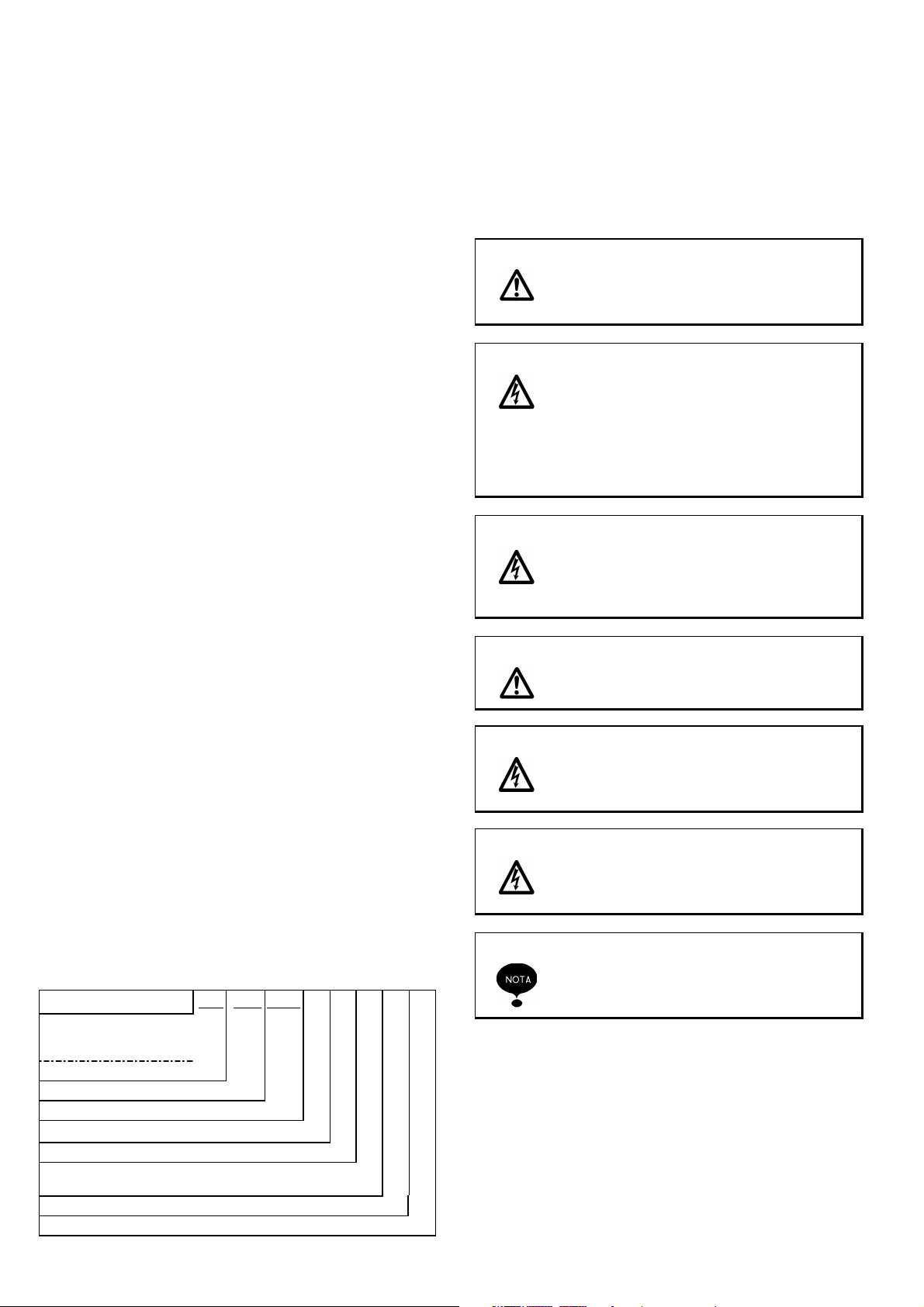
1.3 Machine identification data
Machine acronym
Centrifugal electric pump
Vertical multistage
with “in line” mouth
cast iron base
VLR
VLRI steel base AISI 304
VLRX steel base AISI 316
Nominal delivery in m3/h
Number of stages (= nr. of impellers x 10)
Number of impellers (used when lower
than the number of stages only)
Version with oval flanges
Version with round flanges.
VLR VLRI VLRX 4 - 80 / 7 (A) (F)
1.4 EC declaration of conformity
See page 2
1.5 General information on safety
We recommend to carefully following the instructions contained in
this manual, paying special attention to notes, attention and
danger warnings.
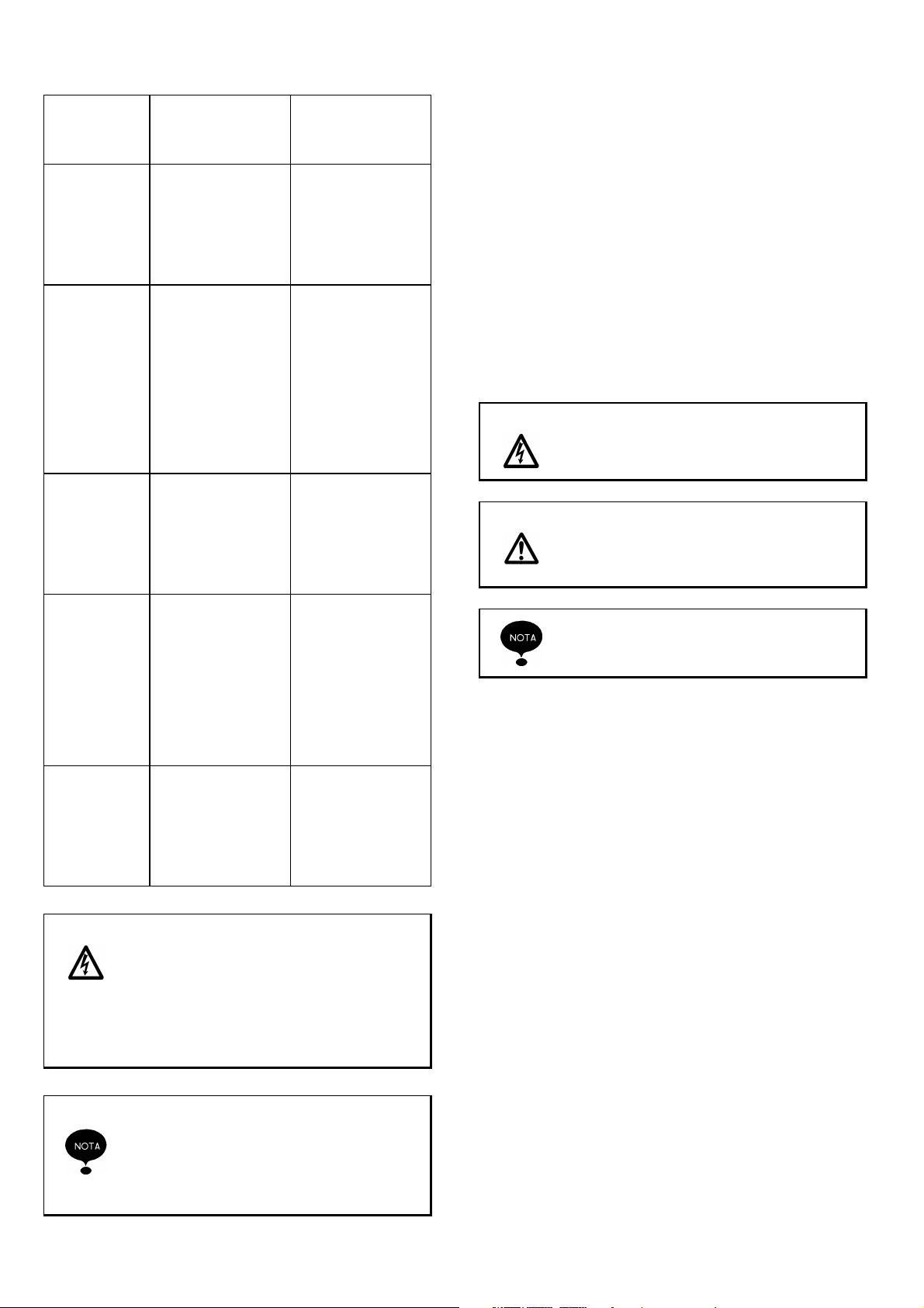
Attention
Danger When carrying out repair or maintenance
Danger
Attention
Danger Before using the motor-pump, check every
Danger When starting the motor-pump (by connect-
The user must always comply with the
accident prevention local prescriptions in
force in the Country where the product is
installed.
operations on the motor-pump, remove the
plug from the outlet and/or turn off the
switch (if existing) disconnecting in this
way the power supply to the motor-pump.
This will prevent the accidental starting
which may cause damages to people and/or
things.
Never carry out maintenance, installation or
handling operations on the motor-pump
with the electric system live: this may
cause serious accidents to people, even
their death.
During operation, do not remove or handle
the motor-pump.
time that the cable and all the electric
devices are efficient, repaired and protected.
ing the plug to the outlet and/or turning off
the switch) make sure not to be barefoot
and that your hand are not wet.
The non-compliance to the procedures and
safety precautions contained in the supplied documents causes the exclusion of
PENTAIR WATER ITALY from any liability.
14
Page 3
1.5.1 Personnel qualification
Qualification and protection restrictions foreseen for the operators
RECCOMENDED
OPERATOR QUALIFICATION
Carrier Knowledge and
command of the
chapters:
- "General information"
- "Description"
- "Installation"
Installer Qualification
complying with the
provisions of the
Country of installation, knowledge and
command of the
chapters:
- "General information"
- "Description"
- "Installation"
User Knowledge and
command of the
chapters:
- "General information"
- "Description"
- "Use"
Maintenance
man
Demolisher Knowledge and
Danger The machine safely operates when used by
Fitness acknowledged by PENTAIR
WATER ITALY,
knowledge and
command of the
chapters:
- "General information "
- "Description"
- "Maintenance"
command of the
chapters:
- "General information"
- "Description"
- "Dismantling"
personnel qualified according to the
instructions contained in this manual and
on board the machine.
All the operations shown by this manual
must only be carried out by qualified
personnel equipped with the protecting
means provided for by this manual
PENTAIR WATER ITALY is not liable in
case of accidents deriving from the use of
non qualified and non authorised personnel
and by the non compliance to the instructions present in this manual an on board
the machine.
INDIVIDUAL
PROTECTION
MEANS
Protective shoes
and gloves
Protective shoes
and gloves
Protective shoes
and gloves, high
temperature
protecting overall
and gloves
Protective shoes
and gloves
Protective shoes
and gloves
1.5.2 Special compliance
The use of personnel having a qualification different from the
specified one may involve risks for people and/or the machine.
1.6 Conventions
1.6.1 Word conventions
The manual adopts the following conventions
-
Machine
-
Authorised technician
-
Skilled technician
: motor-pumps specified in the
“Product specification” "
: person authorised by PENTAIR
WATER ITALY to carry out on the
machine operations not documented
by this manual
: person authorised to carry out on the
machine operations not documented
by this manual after contacting
PENTAIR WATER ITALY
1.6.2 Typographical conventions
Danger Danger indications show the procedure
whose non or partial compliance may
cause physical damages to the operator
Attention
Attention indications show the procedures
whose non or partial compliance may
cause damages to the machine or to the
equipment connected to it
Note indications contain important information highlighted outside the text to which
they refer
1.7 Expected uses
1.7.1 Expected uses
The machine has been designed, manufactured and protected to
allow the conveying, circulation and the increase in pressure of
the following types of fluids:
- Water having a -15 °C to 120 °C temperature (for temperature
lower than 0°C the addition of a fit quantity of ice-preventing
agent is expected)
- Water glycol mixtures (or ice-preventing products having
chemical physical characteristics similar to glycol) with a glycol
percentage up to 50%
- Liquids and waters chemically compatible with the materials that
are part of the machine
- Neutral, non explosive fluids having a viscosity similar to water
The machine has been designed, manufactured and protected to
allow a fluid delivery depending on the required head (see
“Product specification”)
1.7.2 Expected modes of installation
The machine has been designed, manufactured and protected to
be installed both:
- Indoor
- Outdoor with a protection from atmospheric agents
The machine has been designed, manufactured and protected to
be used under the following atmospheric conditions:
- Temperature range: -15 °C to +40 °C
- Allowed relative humidity range: 30 to 90%
15
Page 4
The machine has been designed, manufactured and protected to
be installed in a vertical position with the motor in the upper part.
The machine has been designed, manufactured and protected to
be:
- Fixed on foundations having the characteristics shown in the
appendix “Product specification” paragraph “Foundations”.
- Connected to pipes able to bear the machine weight.
The machine has been designed, manufactured and protected to
be fed by electric power having one of the following characteristics:
- 230 V, 50 Hz, single phase
- 230 V, 50 Hz, three-phase
- 400 V, 50 Hz, three-phase
Different voltages and frequencies are available on request.
1.8 Non expected uses
The machine has not been designed, manufactured, nor protected for all the uses not expressly specified in “Expected uses”.
In particular, the machine has not been designed, manufactured,
nor protected for the conveying, circulation and increase in
pressure of the following fluids:
- Explosive
- Corrosive
- Oil-derivatives and mixtures containing oil-derivatives.
- Mixtures containing material or fibres in suspension
- Sea water
For special uses, please contact out technical office
1.8.1 Liabilities resulting from non expected uses
PENTAIR WATER ITALY is not liable for
possible damages to people, animals or
things resulting from a non-expected use of
the machine.
1.9 Warranty
Non authorised installation, adjustment and
maintenance operations and/or operations
carried out by non qualified personnel
imply the termination of the warranty
1.10 Service
1.11 How to use the supplied documents
We recommend the operators to carefully read the supplied
documents before carrying out any operation on the machine
The supplied documents must be kept for the whole life of the
machine so that it can be easily found when necessary.
If the machine is sold as second-hand, it must be sold together
with the supplied documents.
2. DESCRIPTION
2.1 Description
2.1.1 Architecture and operating principles
VLR motor-pumps are centrifugal, vertical multistage motorpumps with “in-line” suction inlets and delivery.
VLR motor-pumps are directly coupled to an asynchronous single
or three-phase motor with closed casing and external ventilation.
VLR motor-pumps are not self-priming and need a priming
procedure. VLR motor-pumps can be equipped with oval or round
flanges.
2.1.2 Machine structure
Components VLR VLR32
Base EN GJL 200 Cast iron EN GJS 500 Cast iron
Headatock EN GJL 200 Cast iron EN GJL 200 Cast iron
Shaft AISI 316 AISI 431
Impellers and choke AISI 304 AISI 304
External cylinder AISI 304 AISI 304
Tie rods Steel zincate AISI 316
Mechanical
seal
O-ring EPDM EPDM
Seals Paper ---
Componenti VLRI VLRX
Base AISI 316 AISI 316
Headatock See note 1 See note 1
Shaft AISI 316 AISI 316
Impellers and choke AISI 304 AISI 316
External cylinder AISI 304 AISI 316
Tie rods AISI 316 AISI 316
Mechanical
seal
O-ring EPDM EPDM
Seals Paper Paper
rotating Tungsten Tungsten
fixer Tungsten Grafite
rotating Tungsten Tungsten
fixer Tungsten Tungsten
NOTA: EN GJL 200 (ex G220) cast iron with internal steel
drivehead
2.2 Technical features
Machine size and weights
See "Product specification"
Electrical data
See "Product specification " and identification plate.
Pressure
- maximum operating pressure
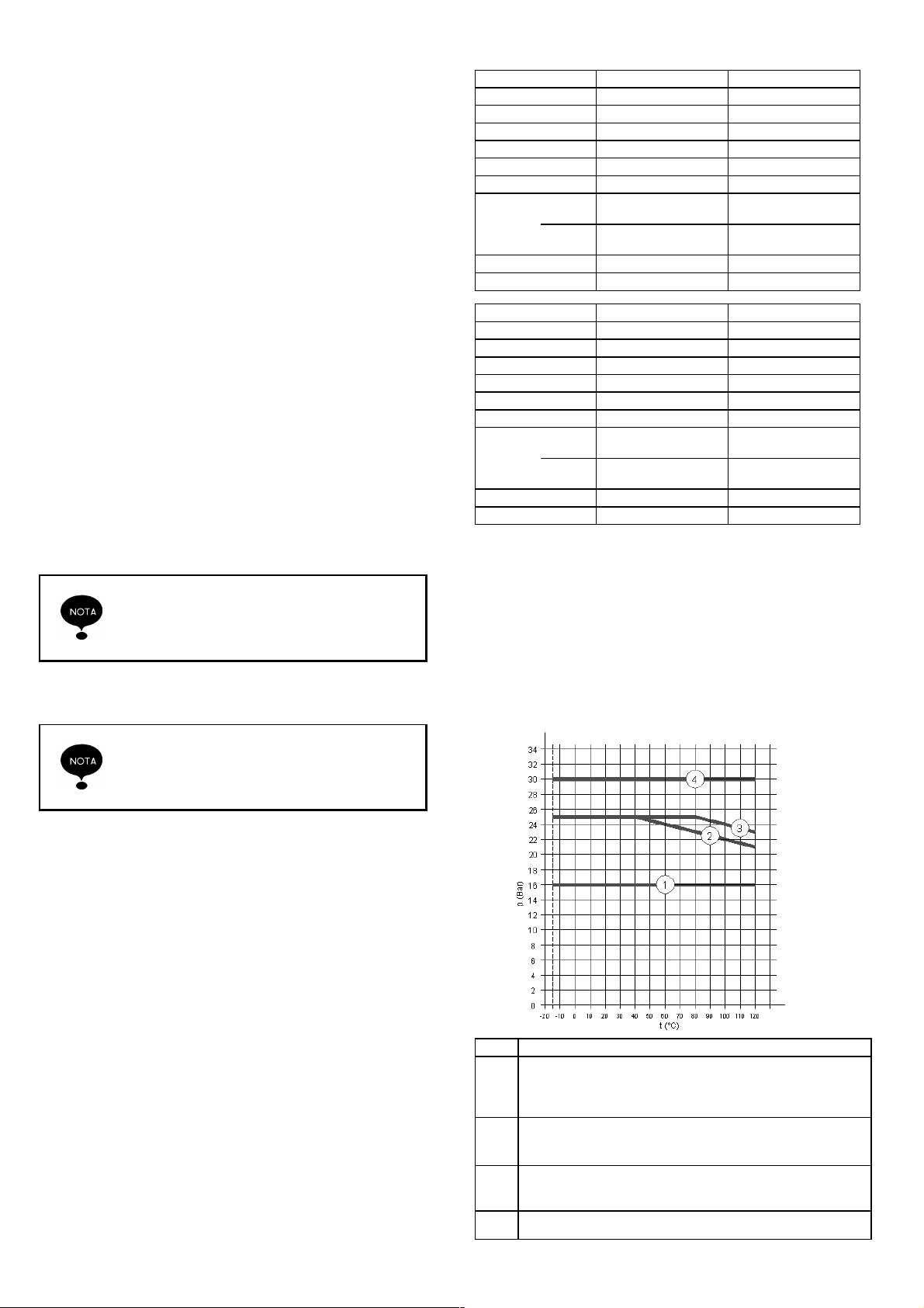
Num.
n
o
p
q
2B - 30/2 A ÷ 2B - 150 A
4 - 20 A ÷ 4 - 160 A
8 - 20 A ÷ 8 - 120 A
2B - 180 F ÷ 2B - 160 F
4 - 190 F ÷ 4 - 260 F
8 - 140 F ÷ 8 - 200 F
16 - 30/2 F - 100 F ÷ 16 - 160 F
32 - 1 ÷ 32 - 14
Machine VLR – VLRI - VLRX
16
Page 5
Machine VLR - VLRI - VLRX
Pressure (bar)
3 4 6 10 15
2B-30/2A x
2B-30 ÷ 2B-110 A x
2B-130 ÷ 2B-260 F x
4-20A ÷ x
4-30 ÷ 4-100 A x
4-120 ÷ 4-260 F x
8-20 A ÷ 8-30 A x
8-40 ÷ 8-200 F x
16-30/2 ÷ 16-30 F x
16-40 ÷ 16-160 F x
32-1 ÷ x
32-2 ÷ 32-4 x
32-5 ÷ 32-10 x
32-11 ÷ 32-14 x
2.2.1 Noise
Sound pressure weighed equivalent continuous maximum level A
issued by the machine: 82 dB (A)
2.2.2 Liability
PENTAIR WATER ITALY is not liable if the values shown in this
paragraph are not complied with.
3. INSTALLATION
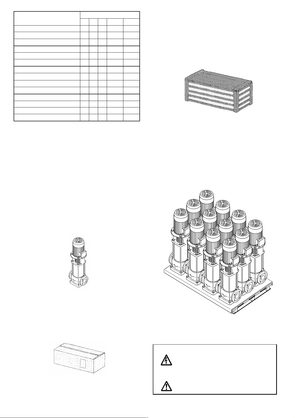
3.1 Hoisting
The machine hoisting can be made under one of the following
conditions:
- Machine free from any type of packaging
- Machine packaged in a cardboard box
- Machine packaged in a wooden crate
- Machine secured on a supporting surface
3.1.1 Machine free from any type of packaging
- for machines having a weight lower than 25 kg: hand hoisting
made by one person
- for machines having a weight between 25 and 50 kg: hand
hoisting made by two persons
- for machines having a weight exceeding 50 kg: hoisting using
hoisting means and sling
3.1.3 Machine packed in a wooden crate
It is possible to hoist more than one machine packed in a wooden
crate depending on the machine weight. Packed machines are
kept in position using wooden spacers
- for machines having a weight lower than 25 kg: hand hoisting
made by one person
- for machines having a weight between 25 and 50 kg: hand
hoisting made by two persons
- for machines having a weight exceeding 50 kg: hoisting using
hoisting means and sling
3.1.4 Machines secured on a supporting surface
It is possible to hoist one machine at a time only:
- for machines having a weight lower than 25 kg: hand hoisting
made by one person
- for machines having a weight between 25 and 50 kg: hand
hoisting made by two persons
- for machines having a weight exceeding 50 kg: hoisting using
hoisting means and sling
3.1.2 Machine packed in cardboard box
It is possible to hoist more than one machine packed in a
cardboard box depending on the machine weight. The packed
machines are kept in position using filling inert material used to fill
the box.
It is possible to hoist more than one machine secured by means
of fixing nuts on a surface having bent sides. The packed
machines are kept in position using wooden spacers.
Position on a suitably sized pallet and hoist using hoisting means.
Danger Risk of machine fall.
Do not stand under the machine during
hoisting.
Attention
Make sure that during hoisting the machine
is kept in vertical position with the motor in
the upper part.
17
Page 6
3.2 Transport
The machine transport must be made under the following
conditions:
- Machine vertical position with the motor in the upper part
- Machine in fixed position without possibility of movements
- Machine protected from atmospheric agents.
Danger
Attention
Make sure that the above listed conditions
are complied with during transportation.
3.3 Storage
3.3.1 Characteristics of the storage area
The storage area must have the following physical characteristics:
- An extent fit for containing the machine and the possible
packaging and allowing the hoisting by means of the foreseen
hoisting means.
- Even and horizontal resting surface.
- Resting surface having a carrying capacity exceeding the
weight of the number of stored machines.
Protection form possible accidental bumps.
3.3.2 Environmental characteristics of the storage area
The storage area must have the following environmental characteristics:
- Allowed temperature range: -15 °C ÷ +50 °C
- Relative humidity range: 30 ÷ 90%
- Protection from atmospheric agents
Danger Possibility of machine fall.
Secure the machine or store it in an
inaccessible place
Do not put the machines one on top of the
other
Attention
Keep the machine in vertical position with
the motor in the upper part
3.4 Preliminary checks
3.4.1 Check for damages
- Check the integrity of the packaging if present
- Open the packaging, if present, and extract the machine
- Check that the received machine matches the ordered one
- Check that the machine is not damaged, in particular check the
integrity of:
- Motor fan cover
- Terminal box cover
- External lining
- Cast iron parts
Attention
Keep the original packaging, if present, for
a possible future transport of the machine
3.4.2 Damage signalling
In case of non-compliance or damages, signal to PENTAIR
WATER ITALY or to the seller the problem within 8 (eight) days
from the purchase date.
3.5 Preparation of the installation area
3.5.1 Characteristics of the installation area
The machine installation area must have the following characteristics:
- Facilitate the positioning and access to the machine
- Allow a safe connection to the electric system
- Allow safe connections to piping
- Presence of a fit natural and/or artificial lighting allowing safe
operation
- A minimum distance of 150mm between any machine point and
any obstacle
- Ensure sufficient ventilation for the motor fan
Attention
Do not cover or obstructs the motor fan
covering grid
Environmental conditions
- Allowed temperature range: -15 °C ÷ +40 °C
- Allowed relative humidity range: 30 ÷ 90%
- Protection from atmospheric agents
Connection
The piping to which the machine must be connected must have
the following characteristics:
- Axiality among the delivery and suction piping with minimum
diameters fit for the machine
- Distance between the two pipelines as shown in the “Product
specification” paragraph “Foundations””
- Fastening to a fixed support, in order not to discharge stresses
and/or vibrations on the machine
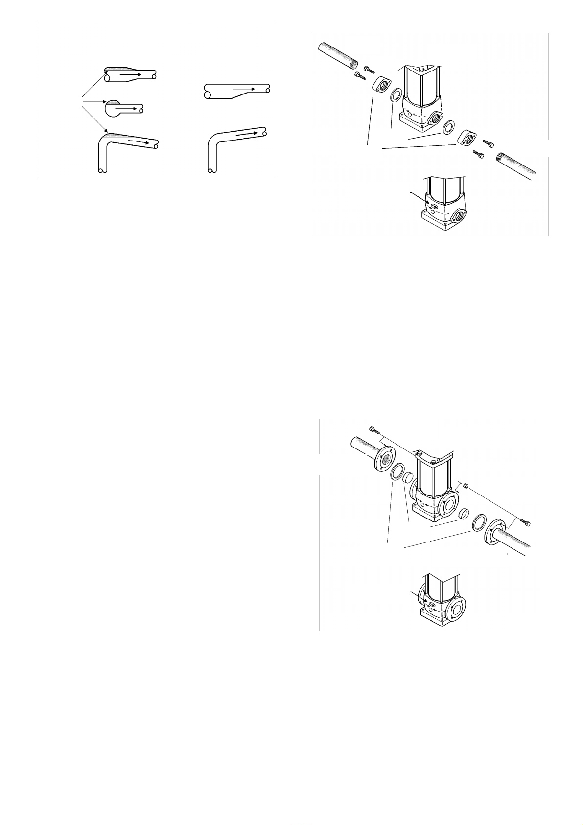
- Absence of air locks, as shown in the piping figure
- Suction piping length reduced as much as possible
- Load losses in the suction piping minimised (if the machine
works in suction mode. See “Machines installed above head”)
- Gates on delivery and suction pipe lines
- If the machine is installed above head, check valve on the
suction piping
- If the machine feeds a boiler, check valve on the delivery piping
- If the fluid circulating in the piping has a temperature exceeding
65 °C, protection against high temperatures
- If the machine can work with a valve closed on the delivery
piping, recycling piping for safeguarding the machine with the
following characteristics:
- Connection between:
- Delivery and suction pipe lines
- Delivery and drain pipe lines
- Control by means of:
- Thermostatic valve
- Solenoid valve controlled by pressure gauge or thermostat
18
Page 7
air locks
PIPING ASSEMBLY
incorrect correct
threaded
pipe
screws
machine with
flange
oval
Power supply
The power supply mains must have the following characteristics:
- A differential protection
- Voltage and frequency values matching the ones shown on the
machine motor rating plate
- A power output not lower than the value shown on the machine
motor rating plate
- An electromagnetic switch having a fit thermal protection
- A self-balanced thermal relay adjusted on the basis of the actual
absorbed current
- A cut-off switch with protecting fuses
- Cables having a section fit for the current absorbed by the
motor.
Access
Connect the machine in a place that can be easily accessed for
maintenance operations
Support
The machine fastening system can match one of the following
systems:
- The machine can be connected to fixed piping able to keep the
machine in its position.
- The machine can be connected to a pipeline and positioned on
a surface having the characteristics shown in “Product specification” paragraph “Foundations”
- The machine can be connected to a pipe line secured by means
of nuts to a surface having the characteristics shown in “Product
specification” paragraph “Foundations”
3.6 Installation
3.6.1 Connection to piping
Machines with oval flanges
Carry out the following operations to connect the machine to
piping:
- Unscrew the screws fastening the counterflanges to the
machines.
- Remove the two counterflanges
- Remove the two gaskets present between counterflanges and
machine base
- Brake the protecting central disks along the marked lines to get
two gaskets with central holes.
- Screw the two counterflanges at the threaded ends of the
piping.
- Position the machine so that the arrows on the base match the
fluid flow direction.
- Position the two circular gaskets between couterflanges and
machine
- Alternatively tighten the screws fastening the counterflanges to
the machine
gaskets
counterflange
flow direction
indication
screws
threaded
pipe
Machine with round flanges
Carry out the following operations to connect the machine to
piping:
- Fit two counterflanges having a size matching those of the
machine flanges to the pipe ends
- Remove the two protecting caps on the machine flanges
- Position the machine so that the arrows on its base match the
fluid flow direction
- Fit the two circular gaskets between counterflanges and flanges
- Fit the screws in the flange and counterflange holes
- Alternatively tighten the nuts on the screws
Counterflange
and pipe
gasket
indication of flow
direction
bolt
(screw and nut)
caps to be
taken away
machine with
round flange
counterflange
and pipe
bolt
(screw and nut)
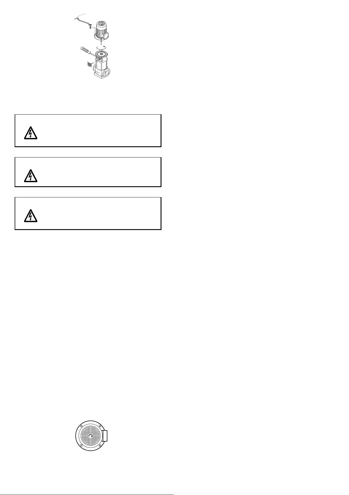
3.6.2 Terminal box position
Carry out the following operations to direct the terminal box in the
required position:
- Remove the connection covering grids
- Unscrew the assembly bolts of motor and machine body
- Rotate the motor of 90° or 180° or 270° (in relation to the initial
position)
- Screw the bolts alternatively and in a uniform way
- Refit the connection covering grids
19
Page 8
3.6.3 Connection to the electric system
Machines with three-phase motors
Danger The installer shall make sure that the power
supply system is fitted with an efficient
ground system according to the provisions
in force.
Danger Make sure that the power supply system is
fitted with a high-sensitiveness differential
= 30 mA (DIN VDE 0100T739).
switch
Danger Before removing the terminal box cover and
before making any operation on the motorpump, make sure that the power supply line
has been cut-off.
Carry out the following operations to connect the machine to the
power supply system:
- Make sure that the motor is fit for the mains voltage
- Cut-off the electric system by means of the cut-off switch
- Unscrew the screws securing the terminal box cover
- Fit the power supply cable in the fairlead
- Connect the phases and the ground to the terminals
- Refit the terminal box cover with the gasket
- Tighten the screws securing the terminal box cover
- Connect the power supply by means of the cut-off switch
- Give a current pulse to the machine
- Check the motor rotation direction
∆
A- If the rotation direction matches the one shown by the arrows
on the machine head, the connections are correct
B- If the rotation direction is the opposite to the one shown by
the arrows on the machine head, carry out the following operations:
-- Cut-off the electric system by means of the cut-off switch
-- Unscrew the screws fastening the terminal box cover
-- Change the connection of two phases
-- Refit the terminal box with the gasket
-- Tighten the screws of the terminal box cover
Machine with single-phase motors
Carry out the following operations to connect the machine to the
power supply system:
- Make sure that the motor is fit for the voltage mains
- Cut-off the electric system by means of the cut-off switch
- Unscrew the screws of the terminal box
- Fit the power supply cable in the fairlead
- Connect the lines and the ground
- Refit the terminal box cover with the gasket
- Tighten the screws of the terminal box cover
- Connect the power supply by means of the cut-off switch
- Give a current pulse to the machine
- Check the rotation direction
A- If the rotation direction matches the rotation direction shown
by the arrows on the machine head, the connections are correct
B- If the rotation direction is the opposite to the one shown by
the arrows on the machine head, carry out the following operations:
-- Cut-off the electric system by means of the cut-off switch
-- Unscrew the screws fastening the terminal box cover
-- Using a jumper, temporarily short-circuit the condenser
terminals
-- Change the jumper positions
-- Remove the jumper
-- Refit the terminal box cover with the gasket
-- Tighten the screws of the terminal box cover
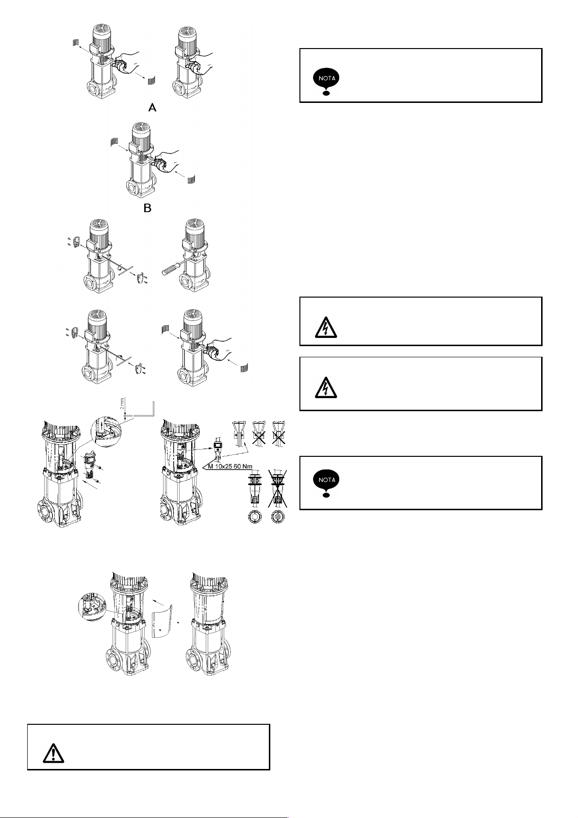
3.7 Adjustment
3.7.1 Machine motor coupling adjustment
Carry out the following operations to adjust the machine-motor
coupling:
- Cut-off the power supply system by means of the cut-off switch
- Unscrew the screws fastening the joint protection
- Remove the joint protection
- Manually rotate the joint
- Check that the joint freely rotates
A- If it freely rotates, carry out the following operations:
-- Refit in place the joint protection
-- Tighten the screws securing the joint protection
B- If the joint does not rotate easily, carry out the following
operations:
-- Loosen the socket-head screws joining the two half-joints
-- Adjust the distance between motor and impeller centres
using a screwdriver as a lever
-- Tighten the socket-head screws joining the two half joints
-- Refit the joint protection
-- Tighten the screws fastening the joint protection
20
Page 9
4.1 Priming
A machine is considered under head if, in
closed circuit systems, the level of the fluid
to be pumped is above the suction inlet of
the machine
4.1.1 Machines installed under head
Carry out the following operations to fill a machine under head:
- Close the gate on the delivery piping
- Unscrew the priming cap
- Loosen the air valve (if present)
- Slowly open the gate on the suction piping
- When the fluid comes out in a continuous way from the priming
cap, carry out the following operations:
-- Screw the priming cap
-- Tighten the air valve (if present)
-- Completely open the gate on the suction piping
-- Open the gate on the delivery piping
Danger Make sure that the priming cap and the air
valve are perfectly tightened
4. USE
Attention
VLR 32
VLR 32
Never start the machine before filling it with
fluid as shown in “Use”, “Priming”.
Danger If the fluid flowing in the pipes and circulat-
ing in the machine has a temperature
higher than 65 °C, Use overall and gloves
protecting against high temperatures
4.1.2 Machines installed above head (suction mode)
A machine is considered above head if, in
open circuit systems, the level of the fluid
to be pumped is under the machine suction
inlet
Carry out the following operation to fill the machine above head:
- Open the gate on the suction piping
- Close the gate on the delivery piping
- Open the priming cap
- Loosen the air valve (if present)
- Rotate the drain and/or discharge cap counterclockwise (if
present)
- Pour the liquid in the machine through the priming cap until it
comes out from it
- When it is no more possible to further fill the machine, carry out
the following operations:
-- Tighten the air cap
-- Tighten the drain and discharge cap (if present)
-- Tighten the air valve (if present)
-- Start the machine
-- Open the gate on the delivery piping
-- Loosen the air valve
-- When the fluid comes, tighten the air valve (if present) or
open the priming cap
-- Stop the machine
21
Page 10
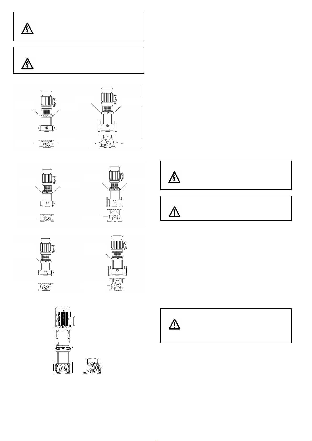
Danger If the fluid flowing in the pipes and circulat-
p
p
e
e
p
ing in the machine has a temperature
higher than 65 °C, Use overall and gloves
protecting against high temperatures
Danger Make sure that the priming cap and the air
valve are perfectly tightened
primimg
cap
Air valve
primimg
cap
Air valve
drain cap
discharge
cap
drain cap
discharg
cap
VLR 2B – VLR 4
primimg
cap
Air valve
primimg
ca
Air valv
drain cap
drain cap
VLR 8 – VLR 16
primimg
primimg
cap
primimg
cap
cap
drain cap
drain ca
VLRI – VLRX
primimg
primimg
drain cap
drain ca
cap
cap
primimg
cap
Air valve
Discarge
cap
Discharge
cap
VLR 32
4.2 Starting
We suggest carrying out the following operations for the first
starting:
- Loosen the air valve (if present) or open the priming cap
22
- If air comes out from the air valve, carry out a new priming
operation
- Tighten the air valve (if present) or open the priming cap
- Open the gate on the delivery piping
- Start the machine
- Slowly open the gate on the delivery piping in order to
prevent water hammering on the delivery piping
- Adjust the thermal relay depending on the current absorbed
by the machine
- Adjust the start and stop pressure of the pressure gauge
controlling the machine operation, if present
4.3 Start and stop frequency control
Carry out the following operations to control the frequency of
starts and stops:
- Control the machine operation for one hour
A- For machines fitted with a motor having an absorbed power
up to 4 kW, if the number of starts/hour is higher than 40,
adjust the machine control equipment so that the frequency
is reduced
B- For machines fitted with a motor having an absorbed power
higher than 4 kW, if the number of starts/hour is higher than
30, adjust the machine control equipment so that the frequency is reduced
Danger In case of high temperature fluids, wait for
an adequate time for the fluid contained in
the machine to cool before unscrewing the
screws securing the machine to piping
Attention
Always check the machine filling. Never
start the machine before filling it up with
fluid as shown in “Use”, “Priming”
5. MAINTENANCE
5.1 Lubrication
The seal on the shaft is self-adjusting. The seal surfaces are
wear-resistant and are lubricated by the pumped fluid.
The machine plain bearings are lubricated by the pumped fluid.
The motor ball bearings are self-lubricated by heat-resistant
grease
Electric motors with grease cup: lubricate every 1500
functioning hours with bearing grease
Attention
If the machines are installed, used and
maintained according to the instructions
contained in this manual, they do not need
lubrication. Comply with the instructions of
this manual
5.2 Temporarily quiescing
Carry out the following operations to set the machine to quiescing
for a long period of time
- Cut-off the power supply system by means of the cut-off switch
Carry out the following operations if it is possible that
-
ambient temperature falls under the pumped fluid freezing temperature:
-
A- If the whole system must be set to quiescing:
-- Empty the system
Page 11
B- If the whole system must not be set to quiescing:
-- Close the gates on the delivery and suction piping
-- Remove the priming cap and the drain and discharge cap
(if present)
-- Discharge all the fluid from the machine
-- Hold the priming cap and the drain and discharge cap for a
new machine employment without refitting them.
Danger In case of high temperature fluids, wait for
an adequate time for the fluid contained in
the machine to cool before unscrewing the
screws securing the machine to piping
Attention
Before restarting the machine fill it as
shown in “Use”, “Priming”.
5.3 Periodical inspection
Carry out the following checks at regular time intervals:
- Hydraulic performances
- No fluid leakage
- Motor overheating
- Relay intervention time
- Start frequency
- Automatic control correct operation
- Vibrations
- Noise
A- If the checks do not find malfunctions, keep on using the
machine up to another inspection.
B- If the checks find malfunctions, carry out the following opera-
tions:
-- Make reference to the table “Defect/Cause” in “Operation
troubles”.
-- If the defect and the cause are listed in the table "Defect/Cause" in "Operation troubles", contact an authorised
technician or a skilled technician and show them the cause
of the found defect.
-- If the defect and the cause are not listed in the table "Defect/Cause" in "Operation troubles", contact an authorised
technician or a skilled technician
5.4 Extraordinary maintenance
For extraordinary maintenance operations, following malfunctions, faults, breaking or technical upgrading only contact an
authorised technician or a skilled technician.
PENTAIR WATER ITALY is not liable and
cancels every warranty contract in case of:
- Operations carried out on the machine
and not documented by this manual
- Extraordinary maintenance operations
carried out by personnel different from
authorised or skilled technicians.
7. DISMANTLING
7.1 Disconnecting the machine
- Cut-off the power supply system by means of the cut-off switch
- Close the gates on the suction and delivery piping
- Unscrew the screws fastening the terminal box cover
- Disconnect the wires from the terminals
- Remove the power supply cable from the fairlead
- Remove the priming cap and the drain and discharge cap
- Discharge all the fluid from the machine
- Unscrew the screws fastening the machine to the pipes
- Unscrew the screws possibly fastening the machine to the
resting surface
- Hoist the machine as shown in “Installation”, “Hoisting”
- Transport the machine as shown in “Installation”, “Transport"
- If the machine is reused, carry out the following operations:
-- Screw the priming cap and the drain and discharge cap on
the machine
-- Refit the terminal box cover with the gasket
-- Tighten the screws securing the terminal box cover
-- If the machine has oval flanges, carry out the following
operations:
-- Unscrew the counterflanges from the pipes
-- Assemble the couterflanges with the gaskets on the machine
-- Close the delivery and suction holes so that dirt cannot enter
in the machine
-- Store the machine as shown in “Installation”, “Storage"
Danger
7.2 Residual risks after disconnection
Attention
If the fluid flowing in the piping and
circulating in the machine has a temperature higher than 65 °C, arrange a protection
against high temperatures around the
machine
PENTAIR WATER ITALY is not liable in
case of recycling or reuse of machine parts
The machine is manufactured using nonbiodegradable materials.
Carry the machine in a deposit equipped for
its disposal
6. OPERATION TROUBLES
Make reference to the table “Defect/Cause”.
23
Page 12
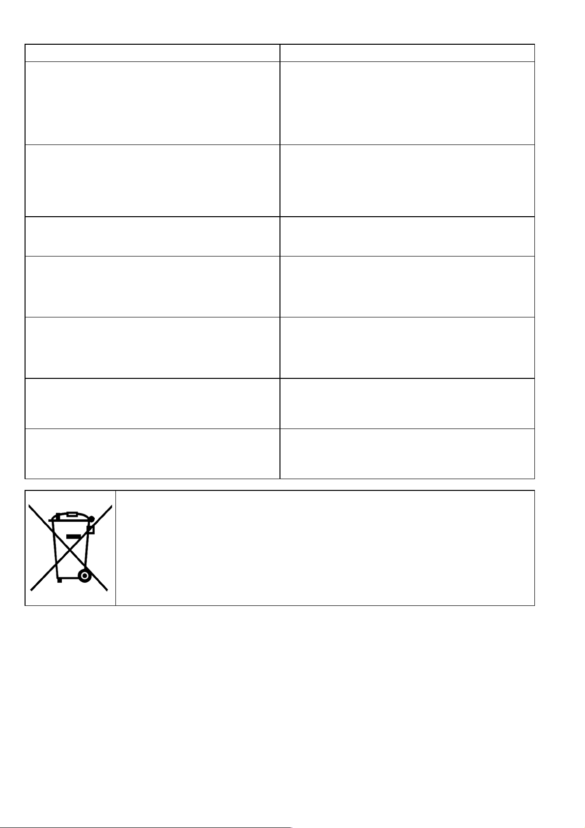
Defect/Causes
Defect Causes
A - At starting, the motor does not run
B - The motor starter thermal relay intervenes when
voltage is connected
C - The thermal relay sometimes intervenes without any
special reason
D - The thermal relay intervention has not occurred by the
machine does not work
E - The machine delivery is not constant
Mains voltage is cut-off
1 -
Blown fuse
2 -
Intervention of the thermal relay
3 -
Either the motor starter contacts do not conduct or the coil
4 -
is faulty
The auxiliary circuit fuses are blown
5 -
The machine motor is faulty
6 -
Blown fuse
1 -
The motor starter contacts are faulty
2 -
The electric connections are faulty
3 -
The motor windings are faulty
4 -
The machine is mechanically blocked
5 -
The thermal relay calibration is too low
6 -
The thermal relay calibration is too low
1 -
Mains voltage periodically lacks
2 -
During peak hours mains voltage is too low
3 -
Mains voltage is cut-of
1 -
Blow fuse
2 -
Either the motor starter contacts do not conduct or the coil
3 -
is faulty
The auxiliary circuit fuses are blown
4 -
The suction pipe is undersized
1 -
The availability of sucked fluid is not enough
2 -
The fluid level is too low
3 -
The head pressure is not enough
4 -
The suction pipe is partially obstructed
5 -
F - The machine runs but does not deliver fluid
G - At stop the machine runs in the opposite direction
Only for EU countries
Do not dispose of electric tools together with household waste material!
In observance of European Directive 2002/96/EC on waste electrical and electronic equipment and its
implementation in accordance with national law, electric tools that have reached the end of their life must
be collected separately and returned to an environmentally compatible recycling facility.
The suction pipe or the pump are obstructed
1 -
The foot valve (or check valve) is blocked in closed position
2 -
Leakage is present in the suction pipe
3 -
Air is present in the suction pipe or in the pump
4 -
The suction pipe or the pump are obstructed
1 -
The foot valve (or check valve) is faulty
2 -
The foot valve (or check valve) is blocked in partial or total
3 -
opening position
24
 Loading...