

Page 1

VLR
VLRI
VLRX
IT - ISTRUZIONI ORIGINALI IN LINGUA ITALIANA
133PAG.RUS1PAG. 45PAG. 67PAG. 89PA G.EDF23PA G.EN 111PA G.NLIT
Page 2
DICHIARAZIONE CE DI CONFORMITÀ
La Ditta PENTAIR INTERNATIONAL SARL dichiara sotto la propria responsabilità che i
prodotti sotto indicati sono conformi ai Requisiti Essenziali di Sicurezza e di Tutela della
Salute di cui alle Direttive sottoelencate e loro successive modifiche.
DECLARATION CE DE CONFORMITE
F D
La Société PENTAIR INTERNATIONAL SARL déclare sous sa propre responsabilité que
les produits sous-mentionnées sont conformes aux Conditions Essentielles de Sécurité
et de Tutelle de la Santé selon les directives indiquées et leurs modifications suivantes.
DECLARACIÓN CE DE CONFORMIDAD
E
La empresa PENTAIR INTERNATIONAL SARL declara bajo la propia responsabilidad
que los productos a continuación indicados cumplen con los requisitos esenciales
de seguridad y de protección de la salud establecidos en las directivas indicadas a
continuación y posteriores modificaciones.
CONFORMITEITSVERKLARING CE
NL
PENTAIR INTERNATIONAL SARL verklaart op eigen verantwoordelijkheid dat de
hieronder genoemde producten voldoen aan de essentiële eisen met betrekking tot
veiligheid en gezondheid van de onderstaande richtlijnen en latere wijzigingen.
TILLKÄNNAGIVANDE OM EU-ÖVERENSSTÄMMELSE
S
Företaget PENTAIR INTERNATIONAL SARL intygar under sitt eget ansvar att de nedan
indikerade produkterna överensstämmer med de hälso- och skyddsnormer som
specificeras i de nedanstående direktiven med senare tillägg.
EU-VAATIMUSTENMUKAISUUSVAKUUTUS
FIN GR
Yhtiö PENTAIR INTERNATIONAL SARL ilmoittaa omalla vastuullaan, että alla osoitetut
tuotteet ovat oleellisten turvallisuus- ja terveydensuojeluvaatimusten mukaisia, joista
alla luetelluissa direktiiveissä sekä niiden myöhemmissä muutoksissa.
DEKLARACJA ZGODNOŚCI Z UE
PL
Firma PENTAIR INTERNATIONAL SARL deklaruje pod własną odpowiedzialnością, że
wskazane poniżej produkty odpowiadają podstawowym Wymogom Bezpieczeństwa
i Ochrony Zdrowia stawianym przez wymienione poniżej Dyrektywy i ich kolejne
modyfikacje.
EURÓPAI UNIÓS MEGFELELÉSI NYILATKOZAT
H
A PENTAIR INTERNATIONAL SARL cég saját felelősségére kijelenti, hogy az alább
megjelölt termékek megfelelnek az alapvető biztonsági és egészségvédelmi
követelményeknek, melyekre az alábbi többször módosított irányelvek vonatkoznak.
AT UYGUNLUK BILDIRISI
TR
PENTAIR INTERNATIONAL SARL firmasi kendi sorumluluğu altlnda asagidaki
elektropompalnn Güvenlik ve Saglik Koruma Şartlarına, sayili direktiflere ve sonraki
değişmelere göre, uygun olduğunu bildirir.
ЕО ДЕЛАРАЦИЯ ЗА СЪОТВЕТСТВИЕ
BG
Фирмата PENTAIR INTERNATIONAL SARL декларира на своя собствена отговорност,
че споменатите по-долу продукти са в съответствие със съответните стандарти за
безопасност и здраве, посочени в изброените директиви и последващи изменения.
DEARBHÚ COMHRÉIREACHTA UM CE
GA
Dearbhaíonn an chuideachta PENTAIR INTERNATIONAL SARL, faoi bhun a fhreagrachta
féin, go bhfuil na táirgí thíosluaite i gcomhréir leis na caighdeáin Sláinte agus
Sábháilteachta arna sonrú sna treoracha sa liosta agus sna leasuithe ina dhiaidh sin.
EB ATITIKTIES DEKLARACIJA
LT
Įmonė PENTAIR INTERNATIONAL SARL išskirtinai savo atsakomybe pareiškia, kad
žemiau minimi gaminiai atitinka atitinkamus Sveikatos ir Saugos standartus, nurodytus
išvardytose direktyvose bei tolesnėse pataisose.
VYHLÁSENIE EHS O ZHODE
SK
Firma PENTAIR INTERNATIONAL SARL prehlasuje na vlastnú zodpovednosť, že
nasledovné výrobky spĺňajú predpisy Bezpečnosti o ochrane zdravia pri práci podľa
nižšie uvedených smerníc v znení neskorších úprav.
GBI
DK
RO
CZ
RUS
EE
LV
MT
SLO
EC DECLARATION OF CONFORMITY
The company PENTAIR INTERNATIONAL SARL declares, under its own responsibility,
that the below mentioned products are compliant with the relevant Health and Safety
standards specified in the listed directives and subsequent amendments.
EG KONFORMITÄTSERKLÄRUNG
Die unterzeichnende Firma PENTAIR INTERNATIONAL SARL erklärt unter eigener
Verantwortung, dass die unten aufgeführten Produkte den wesentlichen Sicherheits- und
Gesundheitsanforderungen der unten angegebenen Richtlinien in der jeweils geltenden
Fassung entsprechen.
DECLARAÇÃO DE CONFORMIDADE CE
P
A empresa PENTAIR INTERNATIONAL SARL declara sob a própria responsabilidade que
os produtos abaixo indicados estão em conformidade com os Requisitos Essenciais
de Segurança e Tutela de Saúde contidos nas Directivas abaixo descritas e sucessivas
modificações.
EF-OVERENSSTEMMELSESERKLÆRING
Undertegnede firma PENTAIR INTERNATIONAL SARL erklærer hermed under ansvar, at
nedennævnte produkter er fremstillet i overensstemmelse med de Væsentlige Sundheds- og
Sikkerhedskrav, der er anført i de nedenundernævnte direktiver og deres efterfølgende ændringer.
SAMSVARSERKLÆRING
N
Firmaet PENTAIR INTERNATIONAL SARL erklærer, under eget ansvar, at de elektriske
pumpene nevnt nedenfor, samsvarer med helse- og sikkerhetsstandardene i direktivene
gjengitt nedenfor.
ΗΛΣΗ ΠPOΣAPΜΟΓΗΣ ΕOΚ
H εταιρεία PENTAIR INTERNATIONAL SARL δηλώνει υπεύθυνα ότι τα παρακάτω
προϊόντα έχουν κατασκευαστεί σύφωνα ε τις Βασικές Απαιτήσεις Ασφαλείας και
Προστασίας της Υγείας των παρακάτω Οδηγιών και επακόλουθων τροποποιήσεών τους.
DECLARAŢIE CE DE CONFORMITATE
Firma PENTAIR INTERNATIONAL SARL declară pe propria ei răspundere că produsele
indicate mai jos sunt în conformitate cu Normele de Siguranţă şi de Tutela Sănătăţii, în
baza directivelor menţionate mai jos şi a succesivelor lor modificări.
PROHLÁŠENÍ ES O SHODĚ
Firma PENTAIR INTERNATIONAL SARL zodpovědně prohlašuje, že níže uvedené výrobky
jsou ve shodě spředpisy o Bezpečnosti práce a ochraně zdraví podle níže uvedených
směrnic směrnic a následujících změn.
ДЕКЛАРАЦИЯ O СООТВЕТСТВИИ EC
Фирма PENTAIR INTERNATIONAL SARL заявляет под свою ответственность, что
нижеуказанные изделия соответствуют основным требованиям по охране здоровья
и безопасности труда, в частности, требованиям перечисленных ниже директив и
их последующих поправок.
VASTAVUSE TUNNISTUS
Ettevõte PENTAIR INTERNATIONAL SARL kuulutab, oma vastutusel, et allpool mainitud
tooted vastavad Tervishoiu ja Ohutuse standarditele, mis on täpsustatud loendatud
direktiivides ja järgnevates parandustes.
EK ATBILSTОBAS SERTIFIKВTS
Uzņēmums PENTAIR INTERNATIONAL SARL paziņo uzņemoties atbildību, ka zemāk
minētie produkti ir atbilst attiecīgajiem Veselības un drošības standartiem, kas noteikti
uzskaitītajās direktīvās un sekojošos labojumos.
EB ATITIKTIES DEKLARACIJA
Il-kumpanija PENTAIR INTERNATIONAL SARL tidikjara, fuq responsabilità tag’ha stess, li
l-prodotti msemmija hawn isfel huma konformi mal-istandards rilevanti dwar is-Sa’’a u
s-Sigurtà kif speifikat fid-direttivi elenkati u sussegwenti emendi.
ES IZJAVA O SKLADNOSTI
Podjetje PENTAIR INTERNATIONAL SARL z vso odgovornostjo izjavlja, da so spodaj
navedeni proizvodi skladni z bistvenimi zahtevami varnosti in varovanja zdravja,
navedenimi v spodaj navedenih direktivah in njihovih kasnejših spremembah.
MOD.
VLR 2B
VLR 4
VLR 8
VLR 16
VLR 32
VLR 66
VLRI 2B
VLRI 4
VLRI 8
VLRI 16
VLRX 2B
VLRX 4
VLRX 8
VLRX 16
DIRECTIVES:
2006/42/EC 2006/95/EC
2004/108/EC
HARMONIZED STANDARDS:
EN 809 EN 60335-1
EN 60335-2-41 EN 61000-6-3
EN 61000-6-1 EN 55014
EN 60555
09
Pentair International S.a.r.l.
Avenue de Sevelin, 18
1004 Lausanne, Switzerland
Vittorio Brundu
PLANT MANAGER
Lugnano (Pisa)
20/12/2012
Page 3
SUMMARY
CHAPTER DESCRIPTION PAGE
1.1 Supplied documents 24
1.2 Information ownership 24
1.3 Machine identification data 24
1.4 EC declaration of conformity 25
1.5 General information on safety 25
1 GENERAL INFORMATION
2 DESCRIPTION
3 INSTALLATION
4 USE
5 MAINTENANCE
6 OPERATION TROUBLES Table 43
7 DISMANTLING
- WARRANTY - 157
1.6 Conventions 27
1.7 Expected uses 27
1.8 Non expected uses 28
1.9 Warranty 28
1.10 Service 29
1.11 How to use the supplied documents 29
2.1 Description 29
2.2 Technical features 30
3.1 Hoisting 31
3.2 Transport 32
3.3 Storage 33
3.4 Preliminary checks 33
3.5 Preparation of the installation area 33
3.6 Installation 35
3.7 Adjustment 37
4.1 Priming 39
4.2 Starting 41
4.3 Start and stop frequency control 41
5.1 Lubrication 42
5.2 Temporarily quiescing 42
5.3 Periodical inspection 42
5.4 Extraordinary maintenance 43
7.1 Disconnecting the machine 44
7.2 Residual risks after disconnection 44
GB
23
Page 4
GB
CHAPTER 1
GENERAL INFORMATION
1.1 SUPPLIED DOCUMENTS
1.1.1 MANUAL
DATA
Instruction manual
Issue 2
Version 082014
Code 253P9070
RECIPIENTS
This manual is dedicated to the operators charged of the machine management during all the phases of its technical life.
CONTENTS
This manual includes the following information:
• Manufacturer declaration
• Information on safety
• Sales information
• Information on documents
These pieces of information are subdivided into the following chapters and appendixes of this manual:
• Chapter 1: General information
• Chapter 2: Description
• Chapter 3: Installation
1.2 INFORMATION OWNERSHIP
The information contained in this manual is owned by PENTAIR INTERNATIONAL S.a.r.l.
The reproduction, also partial, of this manual is forbidden without the express authorisation of PENTAIR INTERNATIONAL S.a.r.l.
The information contained in this manual only concerns the machine specified in the “Product specification” section.
PENTAIR INTERNATIONAL S.a.r.l. reserves the right to make to the machines the changes not specified in “Machine identification
data” whenever deemed right.
1.3 MACHINE IDENTIFICATION DATA
MACHINE ACRONYM DESCRIPTION
VLR VLR cast iron base (centrifugal electric pump vertical multistage with “in line” mouth).
VLRI VLRI steel base AISI 304.
VLRX VLRX steel base AISI 316.
4 - Nominal delivery in m
80 Number of stages (= nr. of impellers x 10).
/ 7 Number of impellers (used when lower than the number of stages only).
(A) Version with oval flanges.
(F) Version with round flanges.
• Machine description
• Transport information
• Storage information
• Installation information
• Chapter 4: Use
• Chapter 5: Maintenance
• Chapter 6: Operating troubles
3
/h.
• Adjustment information
• Use information
• Maintenance information
• Dismantling information
• Chapter 7: Dismantling
• Appendix: Product specification
24
Page 5
1.4 EC DECLARATION OF CONFORMITY
See related page.
1.5 GENERAL INFORMATION ON SAFETY
We recommend to carefully following the instructions contained in this manual, paying special attention to notes, attention and
danger warnings.
DANGER
This appliance is not intended for use by persons (including children) with reduced physical, sensory or mental
capabilities, or lack of experience and knowledge, unless they have been given supervision or instruction concerning use
of the appliance by a person responsible for their safety.
Children should be supervised to ensure that they do not play with the appliance.
WARNNG
Users should always follow the accident prevention laws in force in the country
where the product is installed.
DANGER
Before repairing or servicing the electropump, disconnect it from the socket and/or turn the main switch to Off (when
present) to interrupt the power supplied to the electropump. This prevents the electropump from accidentally restarting
and from causing accidents to people and/or damages to the people.
DANGER
Do not service, install or move the electropump while it is powered, because these operations can cause serious
accidents or even death.
WARNNG
During operation, do not remove or move the electropump.
DANGER
Before using the electropump, always check that the cable and all electric devices are efficient, shielded and protected.
DANGER
When starting the electropump (by inserting the plug into the socket and/or turning the main switch to on), always wear
shoes and make sure that the hands are dry.
NOTE
Failure to follow the safety procedures and precautions contained in the documentation supplied shall relieve PENTAIR
INTERNATIONAL S.a.r.l. from all liability thereof.
GB
25
Page 6
GB
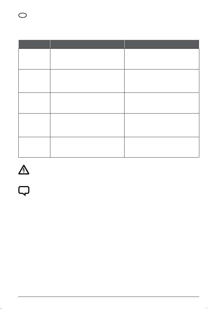
1.5.1 PERSONNEL QUALIFICATION
Qualification and protection restrictions foreseen for the operators.
OPERATOR QUALIFICATION RECCOMENDED INDIVIDUAL PROTECTION MEAN
Knowledge and command of the chapters:
CARRIER
INSTALLER
USER
MAINTENANCE MAN
DEMOLISHER
• General information
• Description
• Installation
Qualification complying with the provisions of the Country of installation,
knowledge and command of the chapters:
• General information
• Description
• Installation
Knowledge and command of the chapters:
• General information
• Description
• Use
Fitness acknowledged by PENTAIR INTERNATIONAL Sarl, knowledge and
command of the chapters:
• General information
• Description
• Maintenance
Knowledge and command of the chapters:
• General information
• Description
• Dismantling
Protective shoes and gloves.
Protective shoes and gloves.
Protective shoes and gloves, high temperature protecting overall and gloves.
Protective shoes and gloves.
Protective shoes and gloves.
DANGER
The machine operates in safety conditions if it is used by qualified personnel in accordance with the instructions and
information contained in this manual and present on board.
All the operations referred to in this manual should be performed by qualified personnel equipped with the protection
means described in this manual.
NOTE
PENTAIR INTERNATIONAL S.a.r.l. shall not be liable for accidents if the machine is used from non qualified or
unauthorised personnel and originating from the failure to follow the instructions contained in this manual and present
on the machine board.
26
Page 7
1.5.2 SPECIAL COMPLIANCE
The use of personnel having a qualification different from the specified one may involve risks for people and/or the machine.
1.6 CONVENTIONS
1.6.1 WORD CONVENTIONS
The following conventions have been adopted throughout the manual
GB
• Machine: elettropompe specificate in
"Scheda prodotto"
1.6.2 TYPESETTING CONVENTIONS
DANGER
Danger indications show the procedure whose non or partial compliance may cause physical damages to the operator.
WARNNG
Attention indications show the procedures whose non or partial compliance may cause damages to the machine or to
the equipment connected to it.
NOTE
Note indications contain important information highlighted outside the text to which they refer.
1.7 EXPECTED USES
1.7.1 EXPECTED USES
The machine has been designed, manufactured and protected to allow the conveying, circulation and the increase in pressure of the
following types of fluids:
• Water having a -15 °C to 120 °C
temperature (for temperature lower
than 0°C the addition of a fit quantity
of ice-preventing agent is expected)
• Authorised technician:
person authorised by PENTAIR
INTERNATIONAL S.a.r.l. to perform
even the operations not specifically
indicated in this manual
• Water glycol mixtures
(or ice-preventing products having
chemical physical characteristics
similar to glycol) with a glycol
percentage up to 50%
• Specialized technician: person
authorised to perform even the
operations not specifically indicated
in this manual after being authorised
by PENTAIR INTERNATIONAL S.a.r.l.
• Liquids and waters chemically
compatible with the materials that
are part of the machine
• Neutral, non explosive fluids
having a viscosity similar to water
The machine has been designed,
manufactured and protected to
allow a fluid delivery depending on
the required head (see “Product
specification”)
27
Page 8

GB
1.7.2 EXPECTED MODES OF INSTALLATION
The machine has been designed, manufactured and protected to be installed both:
• Indoor
The machine has been designed, manufactured and protected to be used under the following atmospheric conditions:
• Temperature range: -15 °C to +40 °C
The machine has been designed, manufactured and protected to be installed in a vertical position with the motor in the upper part.
The machine has been designed, manufactured and protected to be:
• Fixed on foundations having the
characteristics shown in the appendix
“Product specification” paragraph
“Foundations”
The machine has been designed, manufactured and protected to be fed by electric power having one of the following
characteristics:
• 230 V, 50 Hz, single phase
Different voltages and frequencies are available on request.
1.8 NON EXPECTED USES
The machine has not been designed, manufactured, nor protected for all the uses not expressly specified in “Expected uses”.
In particular, the machine has not been designed, manufactured, nor protected for the conveying, circulation and increase in
pressure of the following fluids:
• Explosive
• Corrosive
For special uses, please contact out technical office.
• Outdoor with a protection from
atmospheric agents
• Allowed relative humidity range:
30 to 90%
• Connected to pipes able to bear the
machine weight
• 230 V, 50 Hz, three-phase
• Oil-derivatives and mixtures
containing oil-derivatives
• 400 V, 50 Hz, three-phase
• Mixtures containing material or fibres
in suspension
• Sea water
1.8.1 LIABILITIES RESULTING FROM NON EXPECTED USES
NOTE
PENTAIR INTERNATIONAL S.a.r.l. is not liable for possible damages to people, animals or things resulting from a
non-expected use of the machine.
1.9 GARANZIA
NOTE
Non authorised installation, adjustment and maintenance operations and/or operations carried out by non qualified
personnel imply the termination of the warranty
28
Page 9
1.10 SERVICE
WARNNG
If the pump has been used with noxious or toxic fluids, the pump will be classified as polluted and PENTAIR
INTERNATIONAL S.a.r.l. will have the right to refuse offering its assistance for the pump.
For all assistance requests, contact:
PENTAIR INTERNATIONAL S.a.r.l. – Servizio Assistenza
Via Masaccio, 13
56010 Lugnano - PISA - ITALY
Tel. 050/71.61.11 - Fax 050/70.31.37
1.11 HOW TO USE THE SUPPLIED DOCUMENTS
We recommend the operators to carefully read the supplied documents before carrying out any operation on the machine
The supplied documents must be kept for the whole life of the machine so that it can be easily found when necessary.
If the machine is sold as second-hand, it must be sold together with the supplied documents.
CHAPTER 2
DESCRIPTION
2.1 DESCRIPTION
2.1.1 ARCHITECTURE AND OPERATING PRINCIPLES
• VLR motor-pumps are centrifugal,
vertical multistage motor-pumps with
“in-line” suction inlets and delivery
• VLR motor-pumps are directly
coupled to an asynchronous single or
three-phase motor with closed casing
and external ventilation
• VLR motor-pumps are not
self-priming and need a priming
procedure
• VLR motor-pumps can be equipped
with oval or round flanges
GB
2.1.2 MACHINE STRUCTURE
COMPONENTS VLR VLR32 VLRI VLRX
BASE
HEADATOCK
SHAFT
IMPELLERS AND CHOKE
EXTERNAL CYLINDER
TIE RODS
MECHANICAL SEAL
O-RING
SEALS
NOTE: EN GJL 200 (ex G220) cast iron with internal steel drivehead.
ROTATING Tungsten Tungsten Tungsten Tungsten
FIXER Tungsten Grafite Tungsten Tungsten
Ghisa EN GJL 200 Cast iron Ghisa EN GJS 500 Cast iron AISI 316 AISI 316
Ghisa EN GJL 200 Cast iron Ghisa EN GJL 200 Cast iron See note 1 See note 1
AISI 316 AISI 431 AISI 316 AISI 316
AISI 304 AISI 304 AISI 304 AISI 316
AISI 304 AISI 304 AISI 304 AISI 316
Steel zincate AISI 316 AISI 316 AISI 316
EPDM EPDM EPDM EPDM
Paper - Paper Paper
29
Page 10

GB
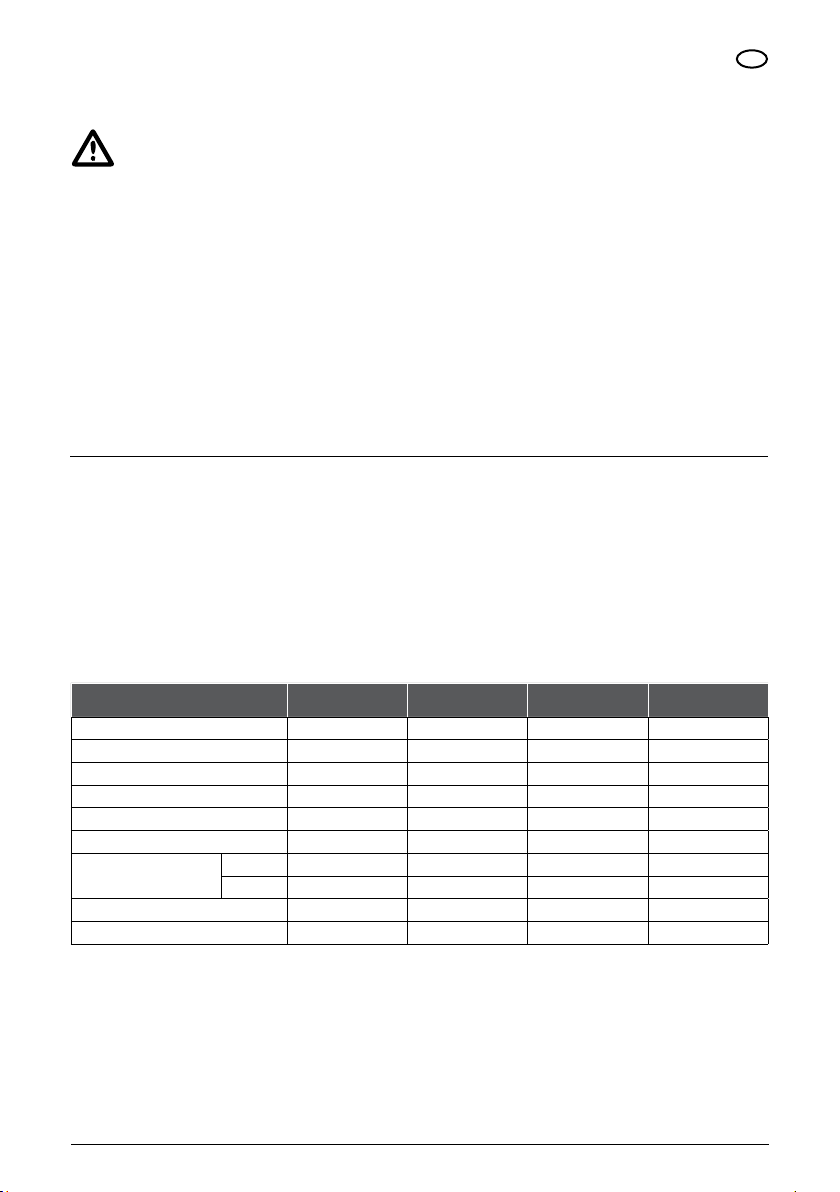
2.2 TECHNICAL FEATURES
• Machine size and weights:
See "Product specification"
• Electrical data:
See "Product specification " and
identification plate
• Pressure:
maximum operating pressure
NUM
1
2
3
4 32 - 1 ÷ 32 - 14
30
MACHINE
VLR VLRI VLRX
2B - 30 / 2 A ÷ 2B - 150 A
4 - 20 A ÷ 4 - 160 A
8 - 20 A ÷ 8 - 120 A
2B - 180F ÷ 2 B - 160 F
4 - 190 F ÷ 4 - 260 F
8 - 140 F ÷ 8 - 200 F
16 - 30 / 2 F-100 F ÷ 16 - 160 F
MACHINE
VLR VLRI VLRX
2B - 30 / 2A
2B - 30 ÷ 2B - 110 A
2B - 130 ÷ 2B - 260 F
4 - 20A ÷
4 - 30 ÷ 4 - 100 A
4 - 120 ÷ 4 - 260 F
8 - 20 A ÷ 8 - 30 A
8 - 40 ÷ 8 - 200 F
16 - 30 / 2 ÷ 16 - 30 F
16 - 40 ÷ 16 - 160 F
32 - 1 ÷
32 - 2 ÷ 32 - 4
32 - 5 ÷ 32 - 10
32 - 11 ÷ 32 - 14
PRESSIONE - BAR
3 4 6 10 15
•
•
•
•
•
•
•
•
•
•
•
•
•
•
Page 11

2.2.1 NOISE
Sound pressure weighed equivalent continuous maximum level A issued by the machine: 82 dB (A)
2.2.2 LIABILITY
PENTAIR INTERNATIONAL S.a.r.l. is not liable if the values shown in this paragraph are not complied with.
CHAPTER 3
INSTALLATION
3.1 HOISTING
The machine hoisting can be made under one of the following conditions:
GB
• Machine free from any type of
packaging
• Machine packaged in a cardboard box
3.1.1 MACHINE FREE FROM ANY TYPE OF PACKAGING
It is possible to hoist one machine at a time only:
3.1.2 MACHINE PACKED IN CARDBOARD BOX
It is possible to hoist more than one machine packed in a cardboard box depending on the machine weight. The packed machines
are kept in position using filling inert material used to fill the box.
• Machine packaged in a wooden crate • Machine secured on a supporting
• For machines having a weight lower
than 25 kg: hand hoisting made by
one person
• For machines having a weight
between 25 and 50 kg: hand hoisting
made by two persons
• For machines having a weight
exceeding 50 kg: hoisting using
hoisting means and sling
• For machines having a weight lower
than 25 kg: hand hoisting made by
one person
• For machines having a weight
between 25 and 50 kg: hand hoisting
made by two persons
• For machines having a weight
exceeding 50 kg: hoisting using
hoisting means and sling
surface
31
Page 12

GB
3.1.3 MACHINE PACKED IN A WOODEN CRATE
It is possible to hoist more than one machine packed in a wooden crate depending on the machine weight. Packed machines are
kept in position using wooden spacers.
• For machines having a weight lower
than 25 kg: hand hoisting made by
one person
• For machines having a weight
between 25 and 50 kg: hand hoisting
made by two persons
• For machines having a weight
exceeding 50 kg: hoisting using
hoisting means and sling
3.1.4 MACHINES SECURED ON A SUPPORTING SURFACE
It is possible to hoist more than one machine secured by means of fixing nuts on a surface having bent sides. The packed machines
are kept in position using wooden spacers. Position on a suitably sized pallet and hoist using hoisting means.
DANGER
Risk of machine fall. Do not stand under the machine during hoisting.
ATTENTION
Make sure that during hoisting the machine is kept in vertical position with the motor in the upper part.
3.2 TRANSPORT
The machine transport must be made under the following conditions:
• Machine vertical position with the
motor in the upper part
DANGER
Make sure that the above listed conditions are complied with during transportation.
32
• Machine in fixed position without
possibility of movements
• Machine protected from atmospheric
agents
Page 13

3.3 STORAGE
3.3.1 CHARACTERISTICS OF THE STORAGE AREA
The storage area must have the following physical characteristics:
GB
• An extent fit for containing the
machine and the possible packaging
and allowing the hoisting by means of
the foreseen hoisting means
3.3.2 ENVIRONMENTAL CHARACTERISTICS OF THE STORAGE AREA
The storage area must have the following environmental characteristics:
• Allowed temperature range:
-15 °C ÷ +50 °C
DANGER
Possibility of machine fall. Secure the machine or store it in an inaccessible place.
Do not put the machines one on top of the other.
ATTENTION
Keep the machine in vertical position with the motor in the upper part.
3.4 PRELIMINARY CHECKS
3.4.1 CHECK FOR DAMAGES
• Check the integrity of the packaging
if present
Check that the machine is not damaged, in particular check the integrity of:
• Motor fan cover
• Terminal box cover
ATTENTION
Keep the original packaging, if present, for a possible future transport of the machine.
• Even and horizontal resting surface
• Resting surface having a carrying
capacity exceeding the weight of the
number of stored machines
• Relative humidity range: 30 ÷ 90% • Protection from atmospheric agents
• Open the packaging, if present, and
extract the machine
• External lining • Cast iron parts
• Protection form possible accidental
bumps
• Check that the received machine
matches the ordered one
3.4.2 DAMAGE SIGNALLING
In case of non-compliance or damages, signal to PENTAIR INTERNATIONAL S.a.r.l. or to the seller the problem within 8 (eight)
days from the purchase date.
3.5 PREPARATION OF THE INSTALLATION AREA
3.5.1 CHARACTERISTICS OF THE INSTALLATION AREA
The machine installation area must have the following characteristics:
• Facilitate the positioning and access
to the machine
• Allow a safe connection to the electric
system
• Allow safe connections to piping
• Presence of a fit natural
and/or artificial lighting allowing safe
operation
• A minimum distance of 150 mm
between any machine point and any
obstacle
• Ensure sufficient ventilation for the
motor fan
33
Page 14

GB
ATTENTION
Do not cover or obstructs the motor fan covering grid.
ENVIRONMENTAL CONDITIONS
• Allowed temperature range:
-15 °C ÷ +40 °C
CONNECTION
The piping to which the machine must be connected must have the following characteristics:
• Axiality among the delivery and
suction piping with minimum
diameters fit for the machine
• Distance between the two pipelines as
shown in the “Product specification”
paragraph “Foundations””
• Fastening to a fixed support, in order
not to discharge stresses and/or
vibrations on the machine
If the machine can work with a valve closed on the delivery piping, recycling piping for safeguarding the machine with the
following characteristics:
PIPING ASSEMBLY
incorrect correct
air locks
• Allowed relative humidity range:
30 ÷ 90%
• Absence of air locks, as shown in the
piping figure
• Suction piping length reduced as
much as possible
• Load losses in the suction piping
minimised (if the machine works
in suction mode. See “Machines
installed above head”)
• Protection from atmospheric agents
• Gates on delivery and suction pipe
lines
• If the machine is installed above head,
check valve on the suction piping
• If the machine feeds a boiler, check
valve on the delivery piping
• If the fluid circulating in the piping
has a temperature exceeding 65 °C,
protection against high temperatures
Connection between:
• Delivery and suction pipe lines
• Delivery and drain pipe lines
Control by mean of:
• Thermostatic valve
• Solenoid valve controlled by
pressure gauge or thermostat
POWER SUPPLY
The power supply mains must have the following characteristics:
• A differential protection
• Voltage and frequency values
matching the ones shown on the
machine motor rating plate
• A power output not lower than the
value shown on the machine motor
rating plate
ACCESS
Connect the machine in a place that can be easily accessed for maintenance operations.
34
• An electromagnetic switch having a fit
thermal protection
• A self-balanced thermal relay
adjusted on the basis of the actual
absorbed current
• A cut-off switch with protecting fuses
• Cables having a section fit for the
current absorbed by the motor.
Page 15

SUPPORT
The machine fastening system can match one of the following systems:
GB
• The machine can be connected to
fixed piping able to keep the machine
in its position.
3.6 INSTALLATION
3.6.1 CONNECTION TO PIPING
MACHINES WITH OVAL FLANGES
Carry out the following operations to connect the machine to piping:
MACHINE WITH ROUND FLANGES
Carry out the following operations to connect the machine to piping:
• The machine can be connected to a
pipeline and positioned on a surface
having the characteristics shown in
“Product specification” paragraph
“Foundations”
• The machine can be connected to a
pipe line secured by means of nuts to
a surface having the characteristics
shown in “Product specification”
paragraph “Foundations”
• Unscrew the screws fastening the
counterflanges to the machines
• Remove the two counterflanges
• Remove the two gaskets present
between counterflanges and machine
base
• Brake the protecting central disks
along the marked lines to get two
gaskets with central holes
• Screw the two counterflanges at the
threaded ends of the piping
• Position the machine so that the
arrows on the base match the fluid
flow direction
• Position the two circular gaskets
between couterflanges and machine
• Alternatively tighten the screws
fastening the counterflanges to the
machine
• Fit two counterflanges having a
size matching those of the machine
flanges to the pipe ends
• Remove the two protecting caps on
the machine flanges
• Position the machine so that the
arrows on its base match the fluid
flow direction
• Fit the two circular gaskets between
counterflanges and flanges
• Fit the screws in the flange and
counterflange holes
• Alternatively tighten the nuts on the
screws
35
Page 16

GB
3.6.2 TERMINAL BOX POSITION
Carry out the following operations to direct the terminal box in the required position:
• Remove the connection covering grids
• Unscrew the assembly bolts of motor
and machine body
• Rotate the motor of 90° or 180° or
270° (in relation to the initial position)
• Screw the bolts alternatively and in a
uniform way
• Refit the connection covering grids
3.6.3 CONNECTION TO THE ELECTRIC SYSTEM
MACHINES WITH THREEPHASE MOTORS
DANGER
The installer shall make sure that the power supply system is fitted with an efficient ground system according to the
provisions in force.
DANGER
Make sure that the power supply system is fitted with a high-sensitiveness differential switch
Δ= 30 mA (DIN VDE 0100T739).
DANGER
Before removing the terminal box cover and before making any operation on the motorpump, make sure that the power
supply line has been cut-off.
Carry out the following operations to connect the machine to the power supply system:
• Make sure that the motor is fit for the
mains voltage
• Cut-off the electric system by means
of the cut-off switch
• Unscrew the screws securing the
terminal box cover
• Fit the power supply cable in the
fairlead
A - If the rotation direction matches the one shown by the arrows on the machine head, the connections are correct.
B - If the rotation direction is the opposite to the one shown by the arrows on the machine head, carry out the following operations:
36
• Connect the phases and the ground to
the terminals
• Refit the terminal box cover with the
gasket
• Tighten the screws securing the
terminal box cover
• Cut-off the electric system by means
of the cut-off switch
• Unscrew the screws fastening the
terminal box cover
• Change the connection of two phases
• Refit the terminal box with the gasket
• Tighten the screws of the terminal
box cover
• Connect the power supply by means
of the cut-off switch
• Give a current pulse to the machine
• Check the motor rotation direction
Page 17

MACHINE WITH SINGLEPHASE MOTORS
Carry out the following operations to connect the machine to the power supply system:
GB
• Make sure that the motor is fit for the
voltage mains
• Cut-off the electric system by means
of the cut-off switch
• Unscrew the screws of the terminal
box
• Fit the power supply cable in the
fairlead
A - If the rotation direction matches the rotation direction shown by the arrows on the machine head, the connections are
correct
B - If the rotation direction is the opposite to the one shown by the arrows on the machine head, carry out the following
operations:
• Cut-off the electric system by means
of the cut-off switch
• Unscrew the screws fastening the
terminal box cover
3.7 ADJUSTMENT
3.7.1 MACHINE MOTOR COUPLING ADJUSTMENT
Carry out the following operations to adjust the machine-motor coupling:
• Cut-off the power supply system by
means of the cut-off switch
• Unscrew the screws fastening the
joint protection
A - If it freely rotates, carry out the following operations:
• Refit in place the joint protection • Tighten the screws securing the joint
• Connect the lines and the ground
• Refit the terminal box cover with the
gasket
• Tighten the screws of the terminal
box cover
• Connect the power supply by means
of the cut-off switch
• Using a jumper, temporarily shortcircuit the condenser terminals
• Change the jumper positions
• Remove the jumper
• Remove the joint protection
• Manually rotate the joint
protection
• Give a current pulse to the machine
• Check the rotation direction
• Refit the terminal box cover with the
gasket
• Tighten the screws of the terminal
box cover
• Check that the joint freely rotates
B - If the joint does not rotate easily, carry out the following operations:
• Loosen the socket-head screws
joining the two half-joints
• Adjust the distance between motor
and impeller centres using a
screwdriver as a lever
• Tighten the socket-head screws
joining the two half joints
• Refit the joint protection
• Tighten the screws fastening the joint
protection
37
Page 18

GB
A
B
VLR 32
38
Page 19

CHAPTER 4
USE
ATTENTION
Never start the machine before filling it with fluid as shown in “Use”, “Priming”.
4.1 PRIMING
NOTE
A machine is considered under head if, in closed circuit systems, the level of the fluid to be pumped is above the suction
inlet of the machine.
4.1.1 MACHINES INSTALLED UNDER HEAD
Carry out the following operations to fill a machine under head:
GB
• Close the gate on the delivery piping
• Unscrew the priming cap
When the fluid comes out in a continuous way from the priming cap, carry out the following operations:
• Screw the priming cap
• Tighten the air valve (if present)
DANGER
Make sure that the priming cap and the air valve are perfectly tightened.
DANGER
If the fluid flowing in the pipes and circulating in the machine has a temperature higher than 65 °C, Use overall
and gloves protecting against high temperatures.
• Loosen the air valve (if present) • Slowly open the gate on the suction
• Completely open the gate on the
suction piping
piping
• Open the gate on the delivery piping
39
Page 20

GB
4.1.2 MACHINES INSTALLED ABOVE HEAD (SUCTION MODE)
NOTE
A machine is considered above head if, in open circuit systems, the level of the fluid to be pumped is under the machine
suction inlet.
Carry out the following operation to fill the machine above head:
• Open the gate on the suction piping
• Close the gate on the delivery piping
• Open the priming cap
When it is no more possible to further fill the machine, carry out the following operations:
• Tighten the air cap
• Tighten the drain and discharge cap
(if present)
• Tighten the air valve (if present)
DANGER
If the fluid flowing in the pipes and circulating in the machine has a temperature higher than 65 °C, Use overall
and gloves protecting against high temperatures.
DANGER
Make sure that the priming cap and the air valve are perfectly tightened.
priming
primimg
cap
cap
drain cap
drain cap
• Loosen the air valve (if present)
• Rotate the drain and/or discharge cap
counterclockwise (if present)
• Start the machine
• Open the gate on the delivery piping
• Loosen the air valve
primimg
priming
cap
air
air
valve
valve
discharge
discharge
cap
cap
cap
drain
drain cap
cap
• Pour the liquid in the machine
through the priming cap until it
comes out from it
• When the fluid comes, tighten the
air valve (if present) or open the
priming cap
• Stop the machine
air
air
valve
valve
discharge
discharge
cap
cap
VLR 2B VLR 4
priming
primimg
cap
cap
drain cap
drain cap
air
valve
valve
primimg
cap
air
cap
drain cap
drain cap
air
valve
valve
air
priming
VLR 8 VLR 16
40
Page 21

priming
primimg
cap
cap
priming
primimg
cap
cap
GB
drain cap
drain cap
drain cap
drain cap
priming
cap
air valve
discharge
cap
discharge
cap
VLRI VLRX VLR 32
4.2 STARTING
We suggest carrying out the following operations for the first starting:
• Loosen the air valve (if present) or
open the priming cap
• If air comes out from the air valve,
carry out a new priming operation
• Tighten the air valve (if present) or
open the priming cap
4.3 START AND STOP FREQUENCY CONTROL
Carry out the following operations to control the frequency of starts and stops (control the machine operation for one hour):
A - For machines fitted with a motor having an absorbed power up to 4 kW, if the number of starts/hour is higher than 40,
adjust the machine control equipment so that the frequency is reduced.
B - For machines fitted with a motor having an absorbed power higher than 4 kW, if the number of starts/hour is higher than
30, adjust the machine control equipment so that the frequency is reduced.
DANGER
In case of high temperature fluids, wait for an adequate time for the fluid contained in the machine to cool before
unscrewing the screws securing the machine to piping.
DANGER
Always check the machine filling. Never start the machine before filling it up with fluid as shown in “Use”, “Priming”.
• Open the gate on the delivery piping
• Start the machine
• Slowly open the gate on the delivery
piping in order to prevent water
hammering on the delivery piping
• Adjust the thermal relay depending
on the current absorbed by the
machine
• Adjust the start and stop pressure of
the pressure gauge controlling the
machine operation, if present
41
Page 22

GB
CHAPTER 5
MAINTENANCE
5.1 LUBRICATION
• The seal on the shaft is self-adjusting
• The seal surfaces are wear-resistant
and are lubricated by the pumped
fluid
ATTENTION
If the machines are installed, used and maintained according to the instructions contained in this manual, they do not
need lubrication. Comply with the instructions of this manual.
5.2 TEMPORARILY QUIESCING
Carry out the following operations to set the machine to quiescing for a long period of time.
Cut-off the power supply system by means of the cut-off switch.
Carry out the following operations if it is possible that ambient temperature falls under the pumped fluid freezing temperature.
A - If the whole system must be set to quiescing, empty the system.
B - SIf the whole system must not be set to quiescing:
• The machine plain bearings are
lubricated by the pumped fluid
• The motor ball bearings are selflubricated by heat-resistant grease
• Electric motors with grease cup:
lubricate every 1500 functioning
hours with bearing grease
• Close the gates on the delivery and
suction piping
• Remove the priming cap and the drain
and discharge cap (if present)
DANGER
In case of high temperature fluids, wait for an adequate time for the fluid contained in the machine to cool before
unscrewing the screws securing the machine to piping.
ATTENTION
Before restarting the machine fill it as shown in “Use”, “Priming”.
5.3 PERIODICAL INSPECTION
Carry out the following checks at regular time intervals:
• Hydraulic performances
• No fluid leakage
• Motor overheating
A - If the checks do not find malfunctions, keep on using the machine up to another inspection.
B - If the checks find malfunctions, carry out the following operations:
• Make reference to the table “Defect/
Cause” in “Operation troubles”
• Discharge all the fluid from the
machine
• Relay intervention time
• Start frequency
• Automatic control correct operation
• If the defect and the cause are
listed in the table "Defect/Cause"
in "Operation troubles", contact an
authorised technician or a skilled
technician and show them the cause
of the found defect
• Hold the priming cap and the drain
and discharge cap for a new machine
employment without refitting them.
• Vibrations
• Noise
• If the defect and the cause are not
listed in the table "Defect/Cause"
in "Operation troubles", contact an
authorised technician or a skilled
technician
42
Page 23

5.4 EXTRAORDINARY MAINTENANCE
For extraordinary maintenance operations, following malfunctions, faults, breaking or technical upgrading only contact an
authorised technician or a skilled technician.
NOTE
PENTAIR INTERNATIONAL S.a.r.l. is not liable and cancels every warranty contract in case of:
• Operations carried out on the machine and not documented by this manual.
• Extraordinary maintenance operations carried out by personnel different from authorised or skilled technicians.
CHAPTER 6
OPERATION TROUBLES
DEFECT CAUSES
1) Mains voltage is cut-off
2) Blown fuse
AT STARTING, THE MOTOR DOES NOT RUN
THE MOTOR STARTER THERMAL RELAY INTERVENES WHEN
VOLTAGE IS CONNECTED
THE THERMAL RELAY SOMETIMES INTERVENES WITHOUT ANY SPECIAL
THE THERMAL RELAY INTERVENTION HAS NOT OCCURRED BY THE
THE MACHINE DELIVERY IS NOT CONSTANT
THE MACHINE RUNS BUT DOES NOT DELIVER FLUID
AT STOP THE MACHINE RUNS IN THE OPPOSITE DIRECTION
REASON
MACHINE DOES NOT WORK
3) Intervention of the thermal relay
4) Either the motor starter contacts do not conduct or the coil is faulty
5) The auxiliary circuit fuses are blown
6) The machine motor is faulty
1) Blown fuse
2) The motor starter contacts are faulty
3) The electric connections are faulty
4) The motor windings are faulty
5) The machine is mechanically blocked
6) The thermal relay calibration is too low
1) The thermal relay calibration is too low
2) Mains voltage periodically lacks
3) During peak hours mains voltage is too low
1) Mains voltage is cut-of
2) Blow fuse
3) Either the motor starter contacts do not conduct or the coil is faulty
4) The auxiliary circuit fuses are blown
1) The suction pipe is undersized
2) The availability of sucked fluid is not enough
3) The fluid level is too low
4) The head pressure is not enough
5) The suction pipe is partially obstructed
1) The suction pipe or the pump are obstructed
2) The foot valve (or check valve) is blocked in closed position
3) Leakage is present in the suction pipe
4) Air is present in the suction pipe or in the pump
1) The suction pipe or the pump are obstructed
2) The foot valve (or check valve) is faulty
3) The foot valve (or check valve) is blocked in partial or total opening position
GB
43
Page 24

GB
CHAPTER 7
DISMANTLING
7.1 DISCONNECTING THE MACHINE
• Cut-off the power supply system by
means of the cut-off switch
• Close the gates on the suction and
delivery piping
• Unscrew the screws fastening the
terminal box cover
• Disconnect the wires from the
terminals
If the machine is reused, carry out the following operations:
• Screw the priming cap and the drain
and discharge cap on the machine
If the machine has oval flanges, carry out the following operations:
• Unscrew the counterflanges from
the pipes
• Assemble the couterflanges with the
gaskets on the machine
DANGER
If the fluid flowing in the piping and circulating in the machine has a temperature higher than 65 °C, arrange a
protection against high temperatures around the machine.
NOTE
PENTAIR INTERNATIONAL S.a.r.l. is not liable in case of recycling or reuse of machine parts.
7.2 RESIDUAL RISKS AFTER DISCONNECTION
ATTENTION
The machine is manufactured using nonbiodegradable materials.
Carry the machine in a deposit equipped for its disposal.
• Remove the power supply cable from
the fairlead
• Remove the priming cap and the drain
and discharge cap
• Discharge all the fluid from the
machine
• Unscrew the screws fastening the
machine to the pipes
• Refit the terminal box cover with the
gasket
• Close the delivery and suction holes
so that dirt cannot enter in the
machine
• Unscrew the screws possibly
fastening the machine to the resting
surface
• Hoist the machine as shown in
“Installation”, “Hoisting”
• Transport the machine as shown in
“Installation”, “Transport"
• Tighten the screws securing the
terminal box cover
• Store the machine as shown in
“Installation”, “Storage"
ONLY FOR EU COUNTRIES
Do not dispose of electric tools together with household waste material!
In observance of European Directive 2002/96/EC on waste electrical and electronic
equipment and its implementation in accordance with national law, electric tools that
have reached the end of their life must be collected separately and returned to an
environmentally compatible recycling facility.
44
Page 25

SOLO PER PAESI UE
Non gettare le apparecchiature elettriche tra i rifiuti domestici. Secondo la Direttiva Europea 2002/96/CE sui rifiuti di apparecchiature elettriche ed elettroniche e la sua attuazione in conformità alle norme nazionali, le apparecchiature elettriche esauste devono
essere raccolte separatamente, al fine di essere reimpiegate in modo eco-compatibile.
POUR LE PAYS EUROPÉENS UNIQUEMENT
F D
Ne pas jeter les appareils électriques dans les ordures ménagères ! Conformément à
la directive européenne 2002/ 96/EG relative aux déchets d’équipements électriques ou
électroniques (DEEE), et à sa transposition dans la législation nationale, les appareils
électriques doivent être collectés à part et être soumis à un recyclage respectueux de
l’environnement.
SÓLO PARA PAÍSES DE LA UNIÓN EUROPEA
E
No deseche los aparatos eléctricos junto noc los residuos domésticos! De conformidad
con la Directiva Europea 2002/96/ CE sobre residuos de aparatos eléctricos y
electrónicos y su aplicación de acuerdo con la legislación nacional, las herramientas
eléctricas cuya vida útil haya llegado a su fin se deberán recoger por separado y
trasladar a una planta de reciclaje que cumpla con las exigencias ecológicas.
ALLEEN VOOR EULANDEN
NL
Geef elektrisch gereedschap niet met het huisvuil mee! Volgens De europese richtlijn
2002/96/eg inzake oude elektrische en Elektronische apparaten en de toepassing
daarvan binnen de Nationale wetgeving, dient gebruikt elektrisch gereedschap
Gescheiden te worden ingezameld en te worden afgevoerd naar Een recycle bedrijf dat
voldoet aan de geldende milieu-eisen.
GÄLLER ENDAST EULÄNDER
S
Elektriska verktyg får inte kastas i hushållssoporna! Enligt direktivet 2002/96/EG som
avser äldre elektrisk och elektronisk utrustning och dess tillämpning enligt nationell
lagstiftning ska uttjänta elektriska verktyg sorteras separat och lämnas till miljövänlig
återvinning.
KOSKEE VAIN EUMAITA
FIN GR
Älä hävitä sähkötyökalua tavallisen kotitalousjätteen mukana! Vanhoja sähkö- ja
elektroniikkalaitteita koskevan EU-direktiivin 2002/96/ETY ja sen maakohtaisten sovellusten mukaisesti käytetyt sähkötyökalut on toimitettava ongelmajätteen keräyspisteeseen ja ohjattava ympäristöystävälliseen kierrätykseen.
Dotyczy tylko państw UE
PL
Nie wyrzucaj elektronarzędzi wraz z odpadami z gospodarstwa domowego! Zgodnie z
Europejską Dyrektywą 2002/96/WE w sprawie zużytego sprzętu elektrotechnicznego i
elektronicznego oraz dostosowaniem jej do prawa krajowego, zużyte elektronarzędzia
należy posegregować i zutylizować w sposób przyjazny dla środowiska.
Csak EU-országok számára
H
Az elektromos kéziszerszámokat ne dobja a háztartási szemétbe! A használt villamos
és elektronikai készülékekről szóló 2002/96/EK irányelv és annak a nemzeti jogba való
átültetése szerint az elhasznált elektromos kéziszerszámokat külön kell gyűjteni, és
környezetbarát módon újra kell hasznosítani.
Sadece AB ülkeleri için
TR
Elektrikli el aletlerini evdeki çöp kutusuna atmayınız!
Kullanılmış elektrikli aletleri, elektrik ve elektronikli eski cihazlar hakkındaki
2002/96/EG Avrupa yönergelerine göre ve bu yönergeler ulusal hukuk kurallarına
göre uyarlanarak, ayrı olarak toplanmalı ve çevre şartlarına uygun bir şekilde tekrar
değerlendirmeye gönderilmelidir.
GBI
DK
RO
CZ
RUS
ONLY FOR EU COUNTRIES
Do not dispose of electric tools together with household waste material! In observance
of European Directive 2002/96/EC on waste electrical and electronic equipment and its
implementation in accordance with national law, electric tools that have reached the end
of their life must be collected separately and returned to an environmentally compatible
recycling facility.
NUR FÜR EULÄNDER
Werfen Sie Elektrowerkzeuge nicht in den Hausmüll! Gemäss Europäischer Richtlinie
2002/96/EG über Elektro- und Elektronik- Altgeräte und Umsetzung in nationales Recht
müssen verbrauchte Elektrowerkzeuge getrennt gesammelt und einer umweltgerechten
Wiederverwertung zugeführt w erden.
DECLARAÇÃO DE CONFORMIDADE CE
P
Não deite ferramentas eléctricas no lixo doméstico! De acordo com a directiva europeia
2002/96/CE sobre ferramnetas eléctricas e electrónicas usadas e a transposição para as
leis nacionais, as ferramentas eléctricas usadas devem ser recolhidas em separado e
encaminhadas a uma instalação de reciclagem dos materiais ecológica.
KUN FOR EULANDE
Elværktøj må ikke bortskaffes som almindeligt affald! I henhold til det europæiske direktiv
2002/96/EF om bortskaffelse af elektriske og elektroniske produkter og gældende national
lovgivning skal brugt elværktøj indsamles separat og bortskaffes på en måde, der skåner miljøet
mest muligt.
KUN FOR EULAND
N
Kast aldri elektroverktøy i husholdningsavfallet! I henhold til EU-direktiv 2002/96/EF om
kasserte elektriske og elekrtoniske produkter og direktivets iverkselting i nasjonal rett,
må elektroverktøy som ikke lenger skal brukes, samles separat og returneres til et
miljøvennlig gjenvinningsanlegg.
Μόνο για τις χώρες της EE
Μην πετάτε τα ηλεκτρικά εργαλεία στον κάδο οικιακών
απαρριμμάτων! Σύμφωνα με την ευρωπαϊκή οδηγία 2002/96/
EK περί ηλεκτρικών και ηλεκτρονικών συσκευών καιτην
ενσωμάτωσή της στο εθνικό δίκαιο, τα ηλεκτρικά εργαλεία
πρέπει να συλλέγονται ξεχωριστά και να επιστρέφονται για
ανακύκλωση με τρόπο φιλικό προς το περιβάλλον.
Numai pentru ţările UE
A nu se arunca echipamentele electrice împreună cu deşeurile domestice.
Conform Directivei Europene 2002/96/CE privind deşeurile din echipamente electrice
şi electronice, şi transpunerea sa conform legilor naţionale, aparaturile eletrice uzate
trebuie colectate separat, pentru a fi refolosite în mod ecologic.
Jen pro státy EU
Elektrické nářadí nevyhazujte do komunálního odpadu! Podle evropské směrnice 2002/96/
EG o nakládání spoužitými elektrickými a elektronickými zařízeními a odpovídajících
ustanovení právních předpisů jednotlivých zemí se použitá elektrická nářadí musí sbírat
odděleně od ostatního odpadu a podrobit se ekologicky šetrnému recyklování.
Только для стран ЕС
Не выкидывайте электроприборы вместе с обычным мусором! В соответствии
с европейской директивой 2002/96/EG об утилизации старых электрических и
электронных приборов и в соответствии с местными законами электроприборы,
бывшие в эксплуатации, должны утилизовываться отдельно безопасным для
окружающей среды способом.
156
Page 26

I
GARANZIA
Questo apparecchio è coperto da garanzia legale in base alle leggi e norme in vigore alla data e nel paese di acquisto, relativamente
ai vizi e difetti di fabbricazione e/o del materiale impiegato. La garanzia si limita alla riparazione o alla sostituzione, presso i Centri
Assistenza autorizzati da PENTAIR INTERNATIONAL S.a.r.l., della pompa o delle parti riconosciute mal funzionanti o difettose.
I componenti soggetti ad usura quali, ad esempio, tenuta meccanica e controfaccia, anelli e guarnizioni di tenuta, girante e parte
idraulica, membrane e cavi elettrici sono garantiti per un periodo non superiore alla loro vita utile. Per il corretto utilizzo e durata
del prodotto, nonché per usufruire del diritto alla garanzia, è necessario far revisionare ed eventualmente sostituire dai centri
assistenza autorizzati tali parti, in funzione del loro utilizzo. Per esercitare il diritto di garanzia, in caso di guasto, rivolgetevi
direttamente al Vostro rivenditore e/o al Centro Assistenza autorizzato.
L’eventuale denuncia del prodotto ritenuto difettoso deve essere avanzata non appena viene riscontrata l’anomalia e comunque
entro e non oltre i termini previsti dalla legge. Il diritto alla garanzia decorre dalla data di acquisto e deve essere dimostrato
dall’acquirente mediante presentazione contestuale del documento comprovante l’acquisto: scontrino fiscale, fattura o documento
di consegna.
La garanzia decade: se il guasto è provocato da trattamenti o operazioni improprie e messa in opera o magazzinaggio errati, errori
di collegamento elettrico o idraulico, mancata o inadeguata protezione. Se l’impianto o l’installazione dell’apparecchio non sono
stati eseguiti correttamente. Se il guasto è dovuto a cause di forza maggiore o altri fattori esterni ed incontrollabili. Se il prodotto
è utilizzato con liquidi abrasivi o corrosivi o diversi da quelli consentiti e comunque non compatibili con i materiali impiegati nella
costruzione delle pompe. Nel caso di utilizzo del prodotto oltre i limiti dichiarati in targa o in condizioni non consentite e di interventi
da parte dell’acquirente o di personale non autorizzato per smontaggio anche parziale del prodotto, modifiche o manomissioni.
Se i materiali sono avariati a seguito del naturale logoramento. Ogni uso diverso da quello indicato sul manuale d’uso e
manutenzione non è garantito se non espressamente indicato per iscritto dal produttore. Si raccomanda sempre di leggere
attentamente e preventivamente il libretto di istruzioni.
Avvertenze:
Qualora il Vostro apparecchio non funzionasse, controllate che il mancato funzionamento non sia provocato da altri motivi, ad
esempio interruzione dell’alimentazione di corrente apparecchi di controllo o di comando oppure manipolazione non appropriata.
ricordarsi di allegare all’apparecchio difettoso la seguente documentazione: Ricevuta di acquisto (fattura, scontrino fiscale)
descrizione dettagliata del difetto riscontrato.
GB
WARRANTY
This device is covered by legal warranty, based on the regulations and standards in force to date and in the country of purchase,
as regards manufacturing and/or material defects.The warranty only covers fixing or replacement of the pump or defective parts,
at the PENTAIR INTERNATIONAL S.a.r.l. authorized service centers.Components subject to wear, such as mechanical seal and
counter face, sealing rings and gaskets, impeller and hydraulic part, membranes and electric cables are guaranteed for a period
not exceeding their useful life. For a proper use and life of the product, and to make use of the warranty rights, have these parts
inspected and optionally replaced at the authorized service centers, based on their use.To exercise warranty rights, in the event
of fault please contact your retailer and/or the authorized service center. Any defects of the product should be reported as soon
as the fault is discovered and in any event, within the terms set forth by law. The warranty is valid as of the date of purchase, as
proved by the user submitting a purchase receipt, invoice or delivery note.The warranty becomes void: if the failure is caused by
improper treatments or operations, incorrect startup or storage, wrong electric or hydraulic connections, failed or inappropriate
protection; if the equipment installation or system were not performed correctly; if the failure is due to force majeure or external
non-controllable factors; if the product is used with abrasive or corrosive liquids or other than those allowed, or in any event not
compatible with the materials used in the pump construction; if the product is used besides the limits reported on the plate or in
conditions not allowed and in the event of unauthorized interventions by the user or other personnel for even partial disassembly
of the product, changes or tampering; if the materials are naturally worn.Any use differing from that indicated on the use and
maintenance manual is not guaranteed, unless otherwise indicated in writing by the manufacturer. Please read the instruction
manual carefully before using the product.
Warnings:
If the unit does not work, check whether the failure is due to other reasons, such as power supply failure, control or command
equipment or wrong handling. Please enclose the following documents with the faulty equipment:Purchase receipt (invoice slip)
Detailed description of the fault found
157
Page 27

credits
PENTAIR INTERNATIONAL S.a.r.l.
Avenue de Sevelin, 18 - 1004 LAUSANNE - SWITZERLAND
All Pentair trademarks and logos are owned by Pentair, inc. All other brand or product names are trademarks or registered marks of their respective owners.
Because we are continously improving our products and services, Pentair reserves the right to change specifications without prior notice.
Pentair is an equal opportunity employer.
253P9070 Rev.1 11/2014 © 2013 Pentair, Inc. All Rights Reserved.
 Loading...