

Page 1
TAURUS™ VS
VARIABLE SPEED PUMP
AQUATIC ECO-SYSTEMS
IMPORTANT SAFETY INSTRUCTIONS
READ AND FOLLOW ALL INSTRUCTIONS
SAVE THESE INSTRUCTIONS
INSTALLATION AND
USER’S GUIDE
Page 2

i
CUSTOMER SERVICE / TECHNICAL SUPPORT
If you have questions about ordering Pentair Aquatic Eco-Systems replacement parts and products, please use the
following contact information:
Customer Service
Monday to Thursday: 8 AM to 7 PM EST
Friday: 8 AM to 5 PM EST
US
Phone: (877) 347-4788
FAX: (407) 886-6787
International
Phone: (407) 886-3939
FAX: (407) 886-4884
TABLE OF CONTENTS
Important Pump Warning and
Safety Instructions ................................................
Pump Overview ......................................................
Pump Overview
General Features
Controller Features
Controller Overview
Control Panel Overview .........................................
Keypad Navigation
Installation ..............................................................
Location
Piping
Fittings and Valves
Electrical Requirements
Wiring Overview and Installation
Control with External Control/Inputs
Connecting to External Controls
Using the Supplied Low Voltage Signal for
Digital Control
Using an External Low Voltage Signal for
Digital Control
External Control Only Mode
Operating the Pump ..............................................
Setting the Clock
Using the Default Schedule
Custom Schedules
Speed Priorities (Non-External Control)
Operating the Pump While Running
Quick Clean
Priming
Quick Clean
Keypad Lockout
Factory Reset
Web site
Visit www.pentairaes.com
Maintenance ..........................................................
ii
1
1
1
1
1
2
2
3
3
3
3
3
4
5
5
5
6
6
7
7
7
8
9
9
9
10
11
11
12
Pump Strainer Basket
Cleaning the Pump Strainer Basket
Winterizing
Servicing ................................................................
Electric Motor Care
Shaft Seal Replacement
Pump Disassembly
Pump Reassembly
Restart Instructions
Troubleshooting ....................................................
Errors and Alarms
Replacement Parts ................................................
Illustrated Parts List
Pump Performance Curves
Pump Specifications
Pump Dimensions
13
13
13
13
14
14
14
14
15
15
16
17
18
18
19
19
19
P/N 351988 Rev. A 11/15/16
TAURUS™ VS Variable Speed Pump Installation and User’s Guide
Page 3
IMPORTANT PUMP WARNING AND SAFETY INSTRUCTIONS
F
ii
IMPORTANT NOTICE
This guide provides installation and operation instructions for
this product. Consult Pentair with any questions regarding
this equipment.
Attention Installer: This guide contains important information about the
installation, operation and safe use of this product. This information should
be given to the owner and/or operator of this equipment after installation or
left on or near the pump. This pump is for use for aquaculture installations
ONLY. Do not use with any type of swimming pool, hot tub, or spa.
Attention User: This manual contains important information that will help
you in operating and maintaining this product. Please retain it for future
reference. This pump is for use for aquaculture installations ONLY. Do not
use with any type of swimming pool, hot tub, or spa. Warnings and safety
instructions for Pentair Aquatic Eco-Systems pumps and other related
products are available at:
http://www.pentairaes.com or call U.S. (877) 347-4788 • International
(407) 886-3939 for additional free copies of these instructions.
READ AND FOLLOW ALL INSTRUCTIONS
SAVE THESE INSTRUCTIONS
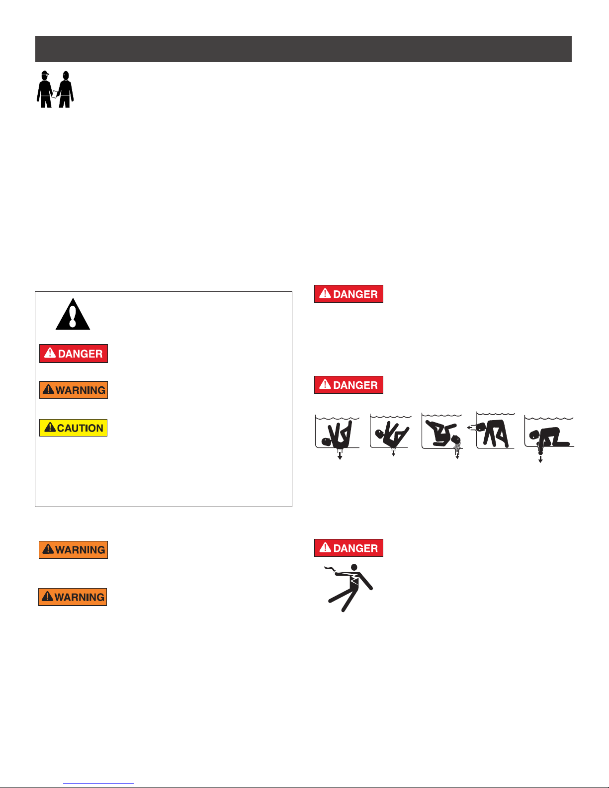
This is the safety alert symbol. When you see this
symbol on your system or in this manual, look for
one of the following signal words and be alert to
the potential for personal injury.
Warns about hazards that can cause death,
serious personal injury, or major property damage
if ignored.
Warns about hazards that may cause death,
serious personal injury, or major property damage
if ignored.
Warns about hazards that may or can cause minor
personal injury or property damage if ignored.
NOTE Indicates special instructions not related to
hazards.
Carefully read and follow all safety instructions in this manual and on
equipment. Keep safety labels in good condition; replace if missing
or damaged.
When installing and using this electrical equipment, basic safety
precautions should always be followed, include the following:
RISK OF ELECTRICAL SHOCK. Connect only to
a branch circuit protected by a ground-fault circuitinterrupter (GFCI). Contact a qualified electrician if you cannot verify that
the circuit is protected by a GFCI.
This unit must be connected only to a supply circuit
that is protected by a ground-fault circuit-interrupter
(GFCI). Such a GFCI should be provided by the installer and should
be tested on a routine basis. To test the GFCI, push the test button.
The GFCI should interrupt power. Push the reset button. Power should
be restored. If the GFCI fails to operate in this manner, the GFCI is
defective. If the GFCI interrupts power to the pump without the test button
being pushed, a ground current is flowing, indicating the possibility of an
electric shock. Do not use this pump. Disconnect the pump and have
the problem corrected by a qualified service representative before using.
General Warnings
• Never open the inside of the drive motor enclosure. There is a
capacitor bank that holds a 230 VAC charge even when there is no
power to the unit.
• The pump is not submersible.
• The pump is capable of high flow rates; use caution when installing
and programming to limit pumps performance potential with old or
questionable equipment.
• Code requirements for the electrical connection differ from country
to country, state to state, as well as local municipalities. Install
equipment in accordance with the current National Electrical Code
and all applicable local codes and ordinances.
• Before servicing the pump; switch OFF power to the pump by
disconnecting the main circuit to the pump.
• This appliance is not intended for use by persons (including
children) of reduced physical, sensory or mental capabilities, or
lack of experience and knowledge, unless they have been given
supervision or instruction concerning the use of the appliance by a
person responsible for their safety.
FAILURE TO FOLLOW ALL INSTRUCTIONS AND
WARNINGS CAN RESULT IN SERIOUS BODILY
INJURY OR DEATH. THIS PUMP SHOULD BE INSTALLED AND SER-
VICED ONLY BY A QUALIFIED SERVICE PROFESSIONAL. INSTALLERS, OPERATORS AND OWNERS MUST READ THESE WARNINGS
AND ALL INSTRUCTIONS IN THE OWNER’S MANUAL BEFORE USING THIS PUMP. THESE WARNINGS AND THE OWNER’S MANUAL
MUST BE LEFT WITH THE PRODUCT OWNER.
SUCTION ENTRAPMENT HAZARD: STAY OFF
THE MAIN DRAIN AND AWAY FROM ALL SUCTION
OUTLETS!
THIS PUMP PRODUCES HIGH LEVELS OF SUCTION AND CREATES
A STRONG VACUUM AT THE MAIN DRAIN AT THE BOTTOM OF THE
BODY OF WATER. THIS SUCTION IS SO STRONG THAT IT CAN TRAP
ADULTS OR CHILDREN UNDER WATER IF THEY COME IN CLOSE
PROXIMITY TO A DRAIN OR A LOOSE OR BROKEN DRAIN COVER
OR GRATE.
RISK OF ELECTRICAL SHOCK OR
ELECTROCUTION: PUMPS REQUIRE HIGH
VOLTAGE WHICH CAN SHOCK, BURN, OR
CAUSE DEATH. BEFORE WORKING ON PUMP!
Always disconnect power to the pump at the circuit
breaker from the pump before servicing the pump.
Failure to do so could result in death or serious injury
to service person, system users or others due to
electric shock.
TAURUS™ VS Variable Speed Pump Installation and User’s Guide
Page 4
iii
IMPORTANT PUMP WARNING AND SAFETY INSTRUCTIONS
NOTE: ALL SUCTION PLUMBING MUST BE INSTALLED IN
ACCORDANCE WITH THE LATEST NATIONAL AND LOCAL CODES,
STANDARDS AND GUIDELINES.
A clearly labeled emergency shut-off switch for the
pump must be in an easily accessible, obvious place.
Make sure users know where it is and how to use it in case of emergency.
For Installation of Electrical Controls at Equipment Pad (ON/OFF
Switches, Timers and Automation Load Center)
Install all electrical controls at equipment pad, such
as on/off switches, timers, and control systems,
etc. to allow the operation (startup, shut-down, or
servicing) of any pump or filter so the user does not
place any portion of his/her body over or near the
pump strainer lid, filter lid or valve closures. This
installation should allow the user enough space to
stand clear of the filter and pump during system
start-up, shut down or servicing of the system filter.
This pump has been evaluated for use with water only.
Before operation, be sure to completely rinse the
pump volute with water.
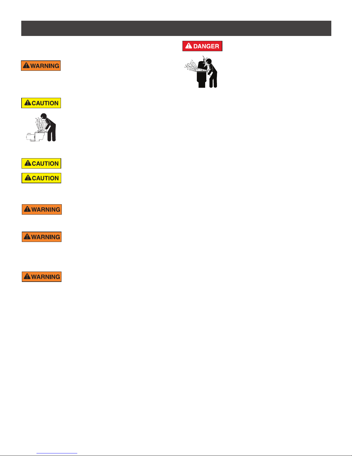
HAZARDOUS PRESSURE: STAND CLEAR OF
PUMP AND FILTER DURING START UP
Circulation systems operate under high pressure.
When any part of the circulating system (i.e.
locking ring, pump, filter, valves, etc.) is serviced,
air can enter the system and become pressurized.
Pressurized air can cause the pump housing cover,
filter lid and valves to violently separate which can
result in severe personal injury or death. Filter tank lid and strainer cover
must be properly secured to prevent violent separation. Stand clear of
all circulation system equipment when turning on or starting up pump.
Before servicing equipment, make note of the filter pressure. Be sure
that all controls are set to ensure the system cannot inadvertently start
during service. Turn off all power to the pump. IMPORTANT: Place filter
manual air relief valve in the open position and wait for all pressure
in the system to be relieved.
Before starting the system, fully open the manual air relief valve and place
all system valves in the “open” position to allow water to flow freely from the
tank and back to the tank. Stand clear of all equipment and start the pump.
IMPORTANT: Do not close filter manual air relief valve until all
pressure has been discharged from the valve and a steady stream
of water appears. Observe filter pressure gauge and be sure it is not
higher than the pre-service condition.
Cord Connected Models Only
RISK OF ELECTRICAL SHOCK. This pump is
supplied with a grounding conductor and grounding
type attachment plug. To reduce the risk of electric shock, be certain that
it is connected only to a properly grounded, grounding-type receptacle.
Pumps improperly sized or installed or used in
applications other than for which the pump was
intended can result in severe personal injury or death. These risks
may include but not be limited to electric shock, fire, flooding, suction
entrapment or severe injury or property damage caused by a structural
failure of the pump or other system component.
The pump can produce high levels of suction within
the suction side of the plumbing system. These
high levels of suction can pose a risk if a person comes within the close
proximity of the suction openings. A person can be seriously injured
by this high level of vacuum or may become trapped and drown. It is
absolutely critical that the suction plumbing be installed in accordance
with the latest national and local codes for aquaculture systems.
SAVE THESE INSTRUCTIONS
General Installation Information
• All work must be performed by a qualified service professional, and
must conform to all national, state, and local codes.
• Install to provide drainage of compartment for electrical components.
• These instructions contain information for a variety of pump models
and therefore some instructions may not apply to a specific model. All
models are intended for use in aquaculture applications. The pump will
function correctly only if it is properly sized to the specific application
and properly installed.
TAURUS™ VS Variable Speed Pump Installation and User’s Guide
Warning Page P/N 352560 Rev. B 12/15
Page 5
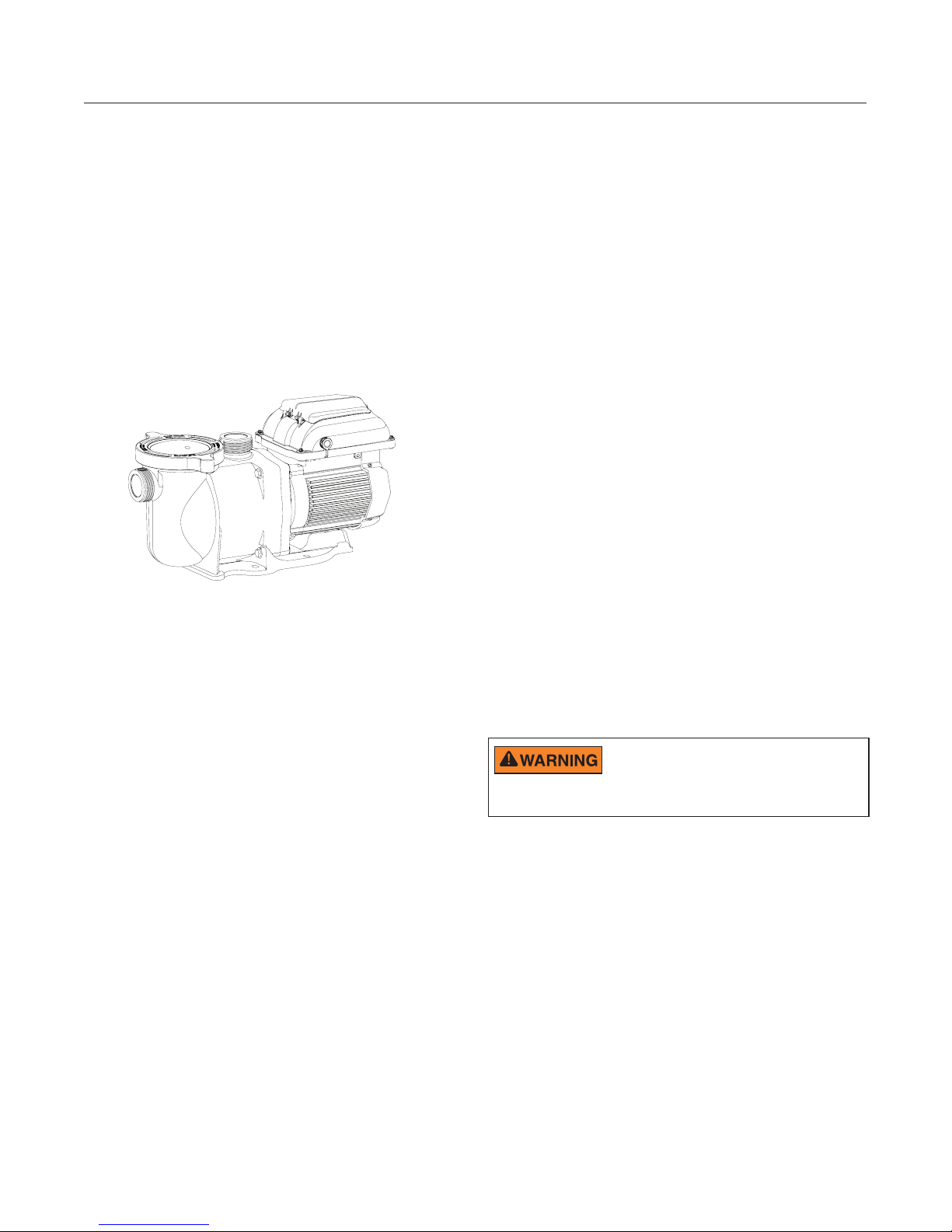
Pump Overview
The perfect choice for all types of installations, the
Taurus™ VS Variable Speed Pump was specifically
designed to be your best choice for a variety of
aquaculture applications.
Thick walled body parts, a heavy duty TEFC motor, and
highly engineered hydraulics result in a rugged and
tested design.
All pumps from Pentair Aquatic Eco-Systems
incorporate innovative hydraulic engineering that has
been refined for over 40 years. Compact, rugged,
and easy to maintain, the Taurus VS pump will deliver
years of reliable service.
1
PUMP OVERVIEW
Controller Features
• Simple user interface
• IPX6 certified UV and rain-proof enclosure
• Onboard time of day schedule
• Adjustable priming mode
• Programmable quick clean mode
• Diagnostic alarm display and retention
• Active power factor correction
• Accepts 99-253V, 50/60Hz input power
• Auto power limiting protection circuit
• 24hr. clock retention for power outages
• Keypad lockout mode
• Accepts low voltage digital inputs from external
controls
Taurus VS Pump
General Features
• Extremely quiet operation
• Unionized fittings (1.5” and 2”) for simple
replacement
• Cam and Ramp™ Lid for easy cleaning and
maintenance
• Super-duty totally enclosed fan cooled (TEFC)
motor for long life
• Integral volute and pot reduce hydraulic noise
• See-through lid permits easy inspection of
strainer basket
• Self-priming for quick, easy start-up
• cUL Listed
Controller Overview
The Taurus VS Variable Speed Pump uses a premium
efficiency variable speed motor that provides tremendous
program flexibility in terms of motor speed and duration
settings. The pump is intended to run at the lowest speeds
needed to maintain a sanitary environment, which in
turn minimizes energy consumption. Reservoir size,
the presence of additional equipment, use of sanitation
chemicals and local environmental factors will impact
optimal programming necessary to maximize energy
conservation.
This pump is for use with 115/208-230 Vrms
nominal, and in aquaculture applications ONLY.
Connection to the wrong voltage, or use in other application may cause
damage to equipment or personal injury.
The integrated electronics interface controls the speed
settings as well as the run durations. The pump can
operate at speeds ranging between 300 and 3450 RPM
and will operate within the voltage range of 99-253
Vrms at either 50 or 60Hz input frequency.
customization may require some trial-and-error to
determine the most satisfactory settings as dictated by
the conditions. In most cases, setting the pump at the
lowest speed for the longest duration is the best str ategy
to minimize energy consumption. However, conditions
may require running the
duration of time each day to maintain proper filtration to
achieve satisfactory sanitation.
pump
at a higher speed for some
Program
TAURUS™ VS Variable Speed Pump Installation and User’s Guide
Page 6
2
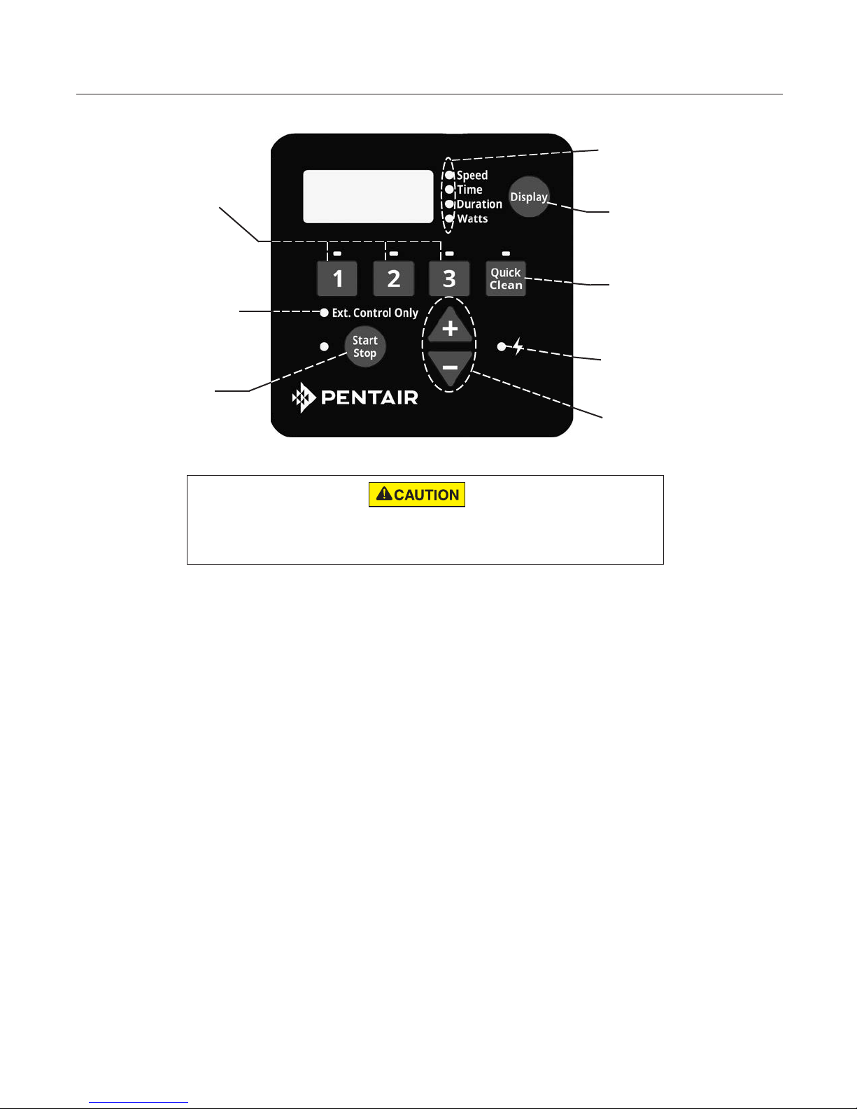
CONTROL PANEL OVERVIEW
(4) Display Mode
LED Indicators
(1) Speed Buttons
(2) External
Control Only
LED Indicator
(3) Start/Stop
Button
If power is connected to the Taurus™ VS Variable Speed Pump motor, pressing any of the following
buttons referred to in this section could result in the motor starting. Failure to recognize this could
(5) Display Button
(6) Quick Clean
Button
(7) Power LED
Indicator
(8) “+” and “-”
Arrows
result in personal injury or damage to equipment.
Keypad Navigation
1. Speed Buttons - Used to select the run speed desired. The LED above the Speed Buttons will illuminate
when that speed is selected or is currently running. A flashing LED indicates that an External Control is
active on that speeds channel.
2. External Control Only LED Indicator - Indicates that the pump is operating in External Control Only
mode. When LED is illuminated the schedule is disabled and the only input is from the low voltage external
controls.
3. Start/Stop Button - Used to Start and Stop the pump. When the pump is stopped and the LED is not
illuminated, the pump is unable to run from any type of input.
4. Display Mode LED Indicators - An illuminated LED indicates the information being displayed on the screen
at any specific point. A flashing LED indicates that the parameter is currently being edited.
5. Display Button - Used to toggle between the different available display modes. This button is also used to
set the 24-hour clock and screen resolution.
6. Quick Clean Button - Used to run a selected speed and duration programmed for Quick Clean. When the
LED is illuminated the Quick Clean schedule is active.
7. Power LED Indicator - An illuminated LED indicates that there is live power being supplied to the pump.
8. “+” and “-” Arrows - Used to make on screen adjustments to the pump settings. The “+” arrow increases
the value of a given setting, while “-” decreases the value of a given setting. Pressing and holding down
either arrow button will increase or decrease the incremental changes faster.
TAURUS™ VS Variable Speed Pump Installation and User’s Guide
Page 7
INSTALLATION
Only a qualified plumbing professional should install the Taurus™ VS Variable Speed Pump. Refer to “Pump Warning
And Safety Instructions” on pages ii-iii for additional installation and safety information.
3
Location
Note: Ensure that the pump is mechanically secured to
the equipment pad.
Be sure the pump location meets the following
requirements:
1. Install the pump as close to the body of water
as possible. To reduce friction loss and improve
efficiency , use short, direct suction and return piping.
2. Install a minimum of 5 feet (1.52 meters) from the
perimeter of the body of water. Canadian installations
require a minimum of 9.8 feet (3 meters) from the
inside wall of the body of water.
3. Install the pump a minimum of 3 feet (.9 meters) from
the heater outlet.
4. Do not install the pump more than 10 feet (3.1 meters)
above the water level.
5. Install the pump in a well ventilated location protected
from excess moisture (i.e. rain gutter downspouts,
sprinklers, etc.).
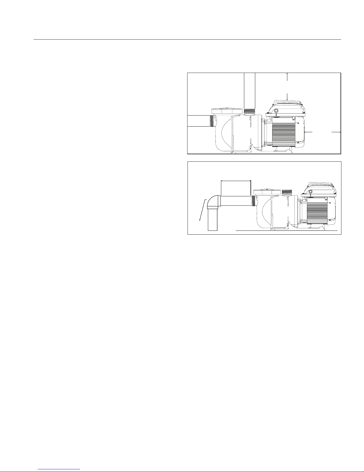
6. Install the pump with a rear clearance of at least 3
inches (7.6 cm) so that the motor can be removed
easily for maintenance and repair. See Figure 1.
Piping
1. For improved plumbing, it is recommended to use
a larger pipe size.
2. Piping on the suction side of the pump should be the
same or larger than the return line diameter.
3. Plumbing on the suction side of the pump should be
as short as possible.
4. For most installations P entair recommends installing
a valve on both the pump suction and return lines
so that the pump can be isolated during routine
maintenance. However, we also recommend that a
valve, elbo w or tee installed in the suction line should
be no closer to the front of the pump than five (5)
times the suction line diameter. See Figure 2.
Example: A 2.5 inch pipe requires a 12.5 inch
(31.8 cm) straight run in front of the suction inlet of
the pump. This will help the pump prime faster and
last longer.
Note: DO NOT install 90° elbows directly into the
pump inlet or outlet.
Figure 1
5 x SUCTION PIPE DIAMETER
ELBOW
6 IN. (15.2 CM)
MINIMUM
3 IN.
MINIMUM
Figure 2
Fittings and V alves
1. Do not install 90° elbows directly into pump inlet.
2. Flooded suction systems should have gate valves installed
on suction and discharge pipes for maintenance, howe ver,
the suction gate valve should be no closer than fiv e times
the suction pipe diameter as described in this section.
3. Use a check valv e in the discharge line when using this
pump for any application where there is significant height
to the plumbing after the pump.
4. Be sure to install check valv es when plumbing in parallel
with another pump. This helps prevent reverse rotation
of the impeller and motor.
Electrical Requirements
• Install all equipment in accordance with the National
Electrical code and all applicable local codes and
ordinances.
• A means for disconnection must be incorporated in the
fixed wiring in accordance with the wiring rules.
TAURUS™ VS Variable Speed Pump Installation and User’s Guide
Page 8
4
RISK OF ELECTRICAL SHOCK OR ELECTROCUTION. The Taurus™ VS Variable Speed Pump must be installed by a
licensed or certified electrician or a qualified service professional in accordance with the National Electrical Code and all applicable local codes and ordinances. Improper installation will create an electrical hazard which could result in death or serious
injury to users, installers, or others due to electrical shock, and may also cause damage to property.
Always disconnect power to the pump at the circuit breaker before servicing the pump. Failure to do so could result in
death or serious injury to service people or others due to electric shock and/or property damage.
Read all servicing instructions before working on the pump.
Wiring Overview and Installation
Power should be turned off when installing,
servicing, or repairing electrical components.
Observe all warning notices posted on the existing equipment, pump,
and in these installation instructions.
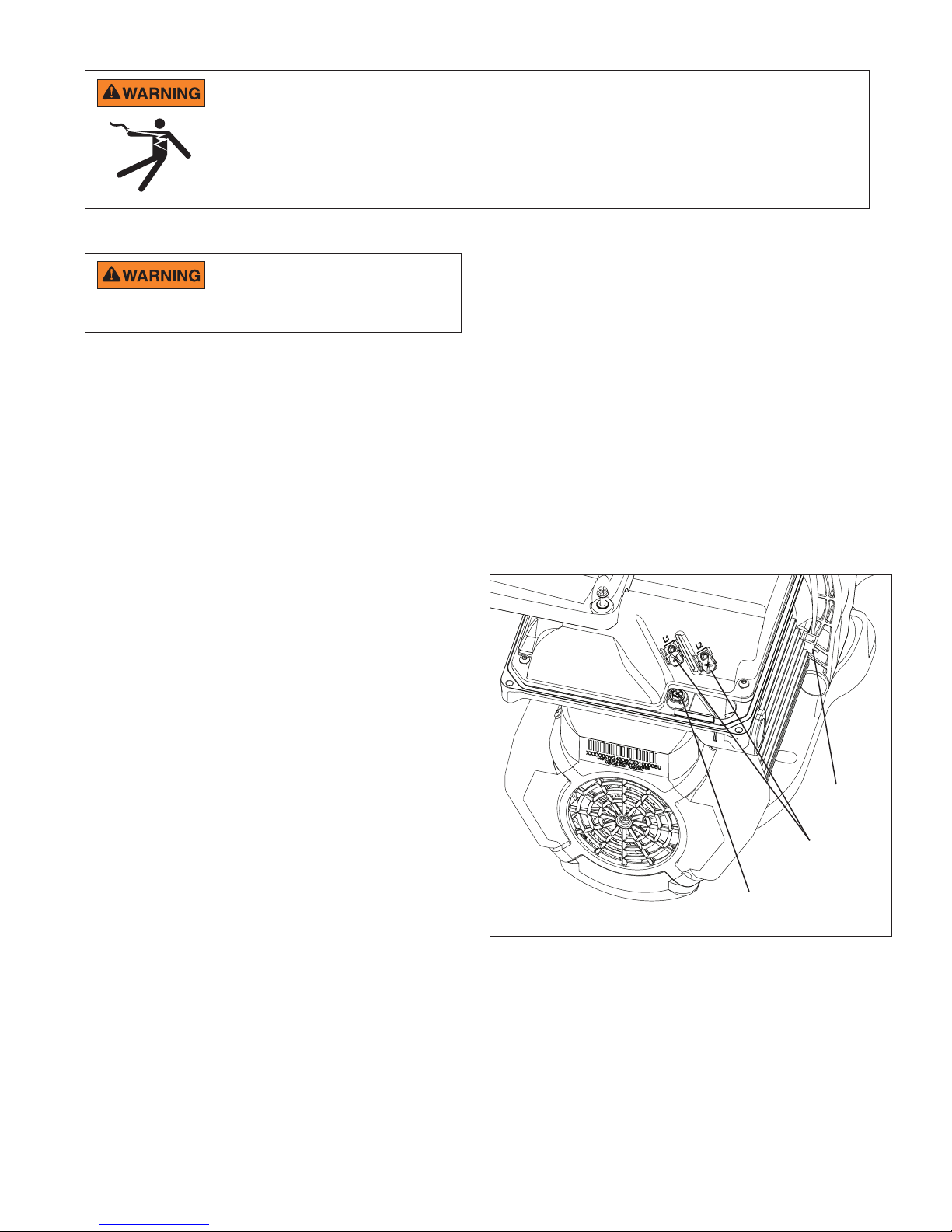
The Taurus VS Variable Speed Pump must be wired
according to the local electrical codes and standards.
Always refer to the National Electrical Code. This
pump should be installed by a licensed electrician.
The pump accepts 99-253V, 50 or 60Hz single phase
input power. The terminal block connections are
capable of handling up to 10AWG solid or stranded
wire. There are also fast-on type quick connectors,
however, check the local electrical codes for the
desired connection method. The connections must
be permanently made to the grounding terminal (see
Figure 3) in the field wiring compartment according
to the local electrical code. The motor controller will
automatically regulate the pump’s speed when running
on lower voltage to keep the current below 13.2A.
There is no wiring change required to run the pump on
110V nominal power, the same terminals are used as
with high voltage wiring.
The drive will operate on 2-phase Line-Line-Ground
electrical systems as well as Line-Neutral-Ground
systems. This pump must be permanently connected
by a circuit breaker as specified in the local electrical
code.
1. Be sure all electrical breakers and switches are turned
off before wiring motor. Always wait five (5) minutes
after disconnecting the power from the pump before
opening or servicing the drive.
2. Choose a wire size for the pump in accordance with
the current National Electrical Code and all applicable
local codes and ordinances. When in doubt use a
heavier gauge (larger diameter) wire. Be sure the
wiring voltage is within the operating range.
3. Be sure all electrical connections are clean and tight.
4. Cut wires to the appropriate length so they do not
overlap or touch when connected to the terminal
board.
5. Permanently ground the motor using the ground
screw located on the inside rear of the controller
interface (see Figure 3). Use the correct wire size
and type specified by the current National Electrical
Code. Be sure the ground wire is connected to an
electrical service ground.
6. Bond the motor to all electrical equipment, metal
conduit and metal piping within 5 feet (1.5 M) of the
inside walls of the body of water in accordance with
the current National Electrical Code. UL requires use
of a solid copper bonding conductor not smaller than
8 AWG. See Figure 3.
Note: For Canada, a 6 AWG or larger solid copper
bonding conductor is required.
7. The pump should be permanently connected to either
a circuit breaker, 2-pole timer or 2-pole relay. If AC
power is supplied by a GFCI circuit breaker, use a
dedicated circuit breaker that has no other electrical
loads.
8. Connect the pump permanently to a circuit. Make
sure no other lights or appliances are on the same
circuit.
Bonding
Lug
AC Power
Connections
Grounding
Figure 3
Screw
The field wiring compartment has a 1/2” NPT threaded
conduit port for the liquid tight fitting.
The bonding lug should be used to bond the motor
frame to the equipment pad.
TAURUS™ VS Variable Speed Pump Installation and User’s Guide
Page 9

Control with External Control and Digital Inputs
RELAY 1 RELAY 2RELAY 3RELAY 4
RELAY
LINE 1
LOAD 1
LOAD 2
LINE 2
POWER RELAY (DPST)
RED
+5V OUTPUT FOR D.I. TRIGGER
GREEN SPEED 1 DIGITAL INPUT
YELLOWSPEED 2 DIGITAL INPUT
ORANGE SPEED 3 DIGITAL INPUT
BROWN
SPEED 4 DIGITAL INPUT
BLACK
GROUND
The user can run the Taurus™ VS Variable Speed Pump with automation external controls, allowing all four
programmed Speeds to be controlled remotely. The pump has a sealed connector that can be used with Pentair
External Control Wiring Kit (Pentair P/N 353129Z) to run the Speeds using digital input signals. When there is an
external low voltage signal present on the Speed Digital Input line, the pump will run the speed programmed for
that Digital Input. The supplied +5V signal is the recommended input used for external control and Speed Digital
Inputs.
Connecting to External Controls
Using the Supplied Low Voltage Signal for Digital Control
This pump provides a low voltage output signal that can be used to trigger its own Digital Inputs. This signal will
need to be switched via the External Control system to engage the speed that it is connected to as in Figure
4. This could be an automation relay or switch in another piece of equipment. This feature could be useful for
ensuring that the pump is running a certain program when a specific speed is needed to perform a task.
The wire included with the External Control Wiring Kit (Pentair P/N 353129Z) will need to be cut to length for the
installation. Do not leave excess wire around the installation, and the wire should be supported by something
rigid if conduit is not used. At one end of the cable is a custom molded, watertight connection that plugs into the
panel connection on the side of the drive. The opposite end has 6 wires that are defined by Table 1 below. When
using the +5V signal supplied by the drive, the speeds should be wired as shown in Figure 4.
When there is a low voltage signal present on the Speed Digital Input line the pump will run the speed that is
programmed for the speed that is being triggered. The +5V signal supplied via the (red) wire is the suggested
input for the Speed Digital Inputs. See Figure 4.
Note: Any relay can be associated to any Digital Input. Figure 4 shows one of many potential wiring options
available to the installer, allowing you to install External Controls in the way that best suits your needs.
Note: This +5V Signal (red wire) is output from the drive only, and should never be wired to another power
supply!
When a Speed Digital Input is triggered, the LED above the Speed button will begin to blink and the display will
toggle between the display parameter and “EC” indicating an External Control is running. The pump will run this
speed as long as the Digital Input trigger is present. This will override the schedule or any user inputs for Speed
selections via the keypad. The Display button is still functional along with the Start/Stop button. Once the Digital
Input trigger is removed from all of the Speed Digital Input wires, the pump will resume the programmed schedule.
5
Figure 4:
External Control Kit Wiring Diagram
Wire
Denition Signal Range
Color
+5V Output for Digital Inputs 0 - 20mA Red
Speed 1 Digital Input 0, 5 - 30V AC/DC Green
Speed 2 Digital Input 0, 5 - 30V AC/DC Yellow
Speed 3 Digital Input 0, 5 - 30V AC/DC Orange
Quick Clean Digital Input 0, 5 - 30V AC/DC Brown
Common Ground 0V Black
Table 1:
Automation Control System Input Wiring Chart
TAURUS™ VS Variable Speed Pump Installation and User’s Guide
Page 10

6
Using an Externally Supplied Low Voltage Signal for External Control
When using an externally supplied low voltage signal as the Digital Input trigger, the wire should be connected as
shown in Figure 5. The low voltage input needs to be within the range of 5-30V AC or DC. In this case the red
+5V supply from the motor control will not be used.
Note: This +5V signal (red wire) is output from the drive only and should never be wired to a voltage
supply!
The external low voltage signal can be regulated by switches or relays to activate the desired Digital Input. If more
than one Digital Input is active at one time then they will be resolved by priority.
EXTERNAL LOW
VOLTAGE SUPPLY
5-30 V AC/DC
GROUND
Figure 5: Low Voltage Power Supply Wiring Diagram
Note: If the pump has been stopped via the Start/Stop button, the pump will not run until the pump is turned back
on by pressing the Start/Stop button. If the Start/Stop LED is illuminated, that indicates the pump is on and will
run via Digital Inputs.
Note: If multiple low voltage triggers are present it will be resolved by this priority: Quick Clean, Speed 3, Speed 2,
and then Speed 1.
RED +5V OUTPUT FOR D.I. TRIGGER
GREEN SPEED 1 DIGITAL INPUT
YELLOWSPEED 2 DIGITAL INPUT
ORANGE SPEED 3 DIGITAL INPUT
BROWN
BLACK
SPEED 4 DIGITAL INPUT
GROUND
External Control Only Mode
External Control Only mode will only allow the pump to run from external controls/inputs. When this mode is
active the programmed pump schedule is deactivated, and user speed requests from the keypad will not be
accepted. If the pump is stopped a user can still program the speeds for all four Speed buttons.
To activate External Control Only mode:
1. Stop the pump by pressing the Start/Stop button.
2. Activate External Control Only mode by pressing
and holding the Start/Stop button for 3 seconds.
3. If successful the LED next to Ext. Control Only will
illuminate. See Figure 6.
4. The Start/Stop button must be pressed again to
allow the pump to run.
To deactivate External Control Only mode:
1. Stop the pump by pressing the Start/Stop button.
2. Deactivate External Control Only mode by pressing
and holding the Start/Stop button for 3 seconds.
3. If successful the LED next to Ext. Control Only will
turn off. See Figure 6.
4. The Start/Stop button must be pressed again to
allow the pump to run.
9:00Pm
TAURUS™ VS Variable Speed Pump Installation and User’s Guide
Figure 6: Activating External Control Only
Page 11

OPERATING THE PUMP
7
Setting the Clock
When the pump is first plugged in, the clock will
blink to indicate that is has not been set. Any daily
schedule set by the user will be based on this clock
setting, so it will be necessary to set the clock first.
To Set the Clock:
1. Press and hold the Display button for 3 seconds.
2. Use the “+” and “-” arrows to choose between a
12 or 24 hour time format.
3. Press Display to advance in the Clock Setup
menu
4. Use the “+” and “-” arrows to change the time to
the correct time of day. In the 12 hour time format
AM/PM will display in the bottom right corner.
5. Press Display to advance.
6. Use the “+” and “-” arrows to adjust the screen
backlight brightness.
7. Press Display to exit the Clock Setup menu. The
clock is now set.
During a power outage, the drive will retain the clock
setting in memory for as long as 24 hours. If the
power is out longer than 24 hours the clock will have
to be set again. If the drive has lost the user set time,
the clock will continuously blink until the time is reset.
Once the time is reset the clock will stop blinking.
Note: When power is returned to the pump after
a prolonged outage (24+ hours) the clock will
automatically set itself to the Speed 1 start time, blink
and advance. The pump will also run the associated
schedule from that start time.
Using the Default Schedule
The default schedule is designed to provide enough
daily turnover to service a typical body of water. See
Table 2 for default schedule.
Duration
(Hours)
SPEED 1 2 3000
SPEED 2 10 1400
SPEED 3 2 2200
Table 2: Default Schedule.
SPEED 1 is set to begin at 8:00am and run at 3000
RPM for a duration of 2 hours. When SPEED 1 is
complete the pump immediately begins running the
default SPEED 2. SPEED 2 is factory default to 1400
RPM and will last for 10 hours. When SPEED 2 has
completed its run the pump will run SPEED 3 at 2200
RPM for a duration of two hours.
After 14 hours of run time and completing its run of
SPEED 3, the pump will enter a stationary/paused
state for the next 10 hours. The pump will restart at
8:00am the next morning and cycle through the default
schedule again. The pump will continue to run in this
in this manner until a custom schedule is programmed
into the drive by the user.
Note: The Start/Stop button must be pressed, and the
LED lit, for the pump to run.
Speed
(RPM)
TAURUS™ VS Variable Speed Pump Installation and User’s Guide
Page 12

8
Custom Schedules
To customize the run schedule for your Taurus™ VS
Variable Speed Pump, the pump must be stopped. Be
sure that the Start/Stop button LED is not illuminated.
Programming a Custom Schedule:
Note: When programming, the LED light next to the
parameter (“Speed”, “Time” and “Duration”) you are
setting will blink.
1. Stop the pump if it is running by pressing the
Start/Stop button.
2. Press the “1” button. The LED above the selected
SPEED will begin to blink and the “Speed”
parameter LED will blink while editing.
See Figure 7.
3000
Figure 7: Setting Speed
3. Use the “+” and “-” arrows to adjust the speed in
RPM for SPEED 1.
Note: Speed is adjusted up or down by increments
of 10 RPM.
4. Press the “1” button again and the display will
change to SPEED 1 start time. The “Time”
parameter LED will begin to blink. See Figure 8.
8:00AM
Figure 8: Setting Start Time
5. Use the “+” and “-” arrows to adjust the daily start
time for SPEED 1.
6. Press the “1” button again and the display will
change to SPEED 1 duration. The “Duration”
parameter LED will begin to blink. See Figure 9.
2:00
Figure 9: Setting Duration
7. Use the “+” and “-” arrows to adjust the duration for
SPEED 1 in hours and minutes.
Note: The duration parameter is adjusted in 15
minute increments.
8. Pressing the “1” button will continue to cycle
through these parameters, but the changes are
immediately saved as they are adjusted.
9. Press the “2” button. The LED above SPEED 2 will
begin to flash and the corresponding parameter
LED will flash while editing.
10. Use the “+” and “-” arrows to adjust the speed in
RPM for SPEED 2.
11. Press the “2” button again and the display will
change to SPEED 2 duration.
Note: SPEEDs 2 and 3 do not have a start time,
as they begin their duration immediately after the
previous SPEED finishes.
12. Use the “+” and “-” arrows to adjust the duration for
SPEED 2 in hours and minutes.
13. Repeat steps 9-12 to program SPEED 3 and
QUICK CLEAN.
Note: Remember that the duration allowed for
SPEED 3 will be limited to the remaining time in
a 24 hour day. Any time in the 24 hour day not
programmed into SPEEDs 1-3, the pump will
remain in a stationary state.
[ SPEED 1 + SPEED 2 + SPEED 3 < 24 Hours ]
14. Press the Start/Stop button and ensure the LED
is lit. The pump is now on and will run the custom
user-programmed schedule.
Note: If the pump has been stopped via the Start/
Stop button, the pump will not run until the pump
is turned back on by the Start/Stop button. If the
Start/Stop LED is illuminated then the pump is on
and will run the programmed schedule.
TAURUS™ VS Variable Speed Pump Installation and User’s Guide
Page 13

9
Note: If a user wants to have a period of time
during the day when the pump is not running, any
of the SPEEDs can be programmed to 0 RPM. This
will cause the pump to remain stationary/paused
throughout the duration of that SPEED.
Speed Priorities (Non-External Control)
For schedule duration settings, SPEEDs are prioritized
in numerical order: SPEED 1 -> SPEED 2 -> SPEED
3. SPEED 1 is the highest priority, while SPEED 3 is
the lowest.
The drive will not allow a user to program a schedule
of more than 24 hours. When the 24th hour of duration
is programmed it will take time from the lower priority
speeds in order to add them to the SPEED currently
being adjusted.
Example:
Starting Schedule (Before Adjustment)
SPEED 1 duration = 20 hours
SPEED 2 duration = 2 hours
SPEED 3 duration = 2 hours
If the user reprograms SPEED 1 to run for 23 hours,
SPEED 2 (lower priority speed) will automatically
adjust to a 1 hour duration and SPEED 3 (lowest
priority speed) will adjust to a 0 hour duration.
End Schedule (After Adjustment)
SPEED 1 duration = 23 hours
SPEED 2 duration = 1 hour
SPEED 3 duration = 0 hours
Operating the Pump While Running
If power is connected to the pump motor,
pressing any of the following buttons referred to
in this section could result in the motor starting. Failure to recognize
this could result in personal injury or damage to equipment.
Pressing the Display button will cycle through the
current parameters.
• Speed — current run speed
• Time — current time of day
• Duration — amount of time remaining at the
current run speed
• Watts — amount of watts currently being
consumed
Pressing any of the Speed Buttons (“1”, “2”, “3”,
“Quick Clean”) while the pump is running will act as a
temporary override. It will run the speed and duration
that is programmed for that button. Once completed
it will default back to the appropriate point in the
programmed schedule.
Note: If you adjust the speeds of the schedule while
the pump is running, it will run the adjusted speed
for the rest of the current duration, but will not save
the adjustments. Exception: Speed and Duration
adjustments to QUICK CLEAN will always be
immediately saved.
Quick Clean
When running Quick Clean, pressing the “+” or “-” arrows
will change the speed accordingly. Pressing the Quick
Clean button again within 10 seconds of pressing the “+”
or “-” arrows will allow you to adjust the duration of Quick
Clean via the “+” and “-” arrows. These changes will be
saved immediately and will become the new defaults for
Quick Clean. Pressing the Quick Clean button again will
cycle through the two Quick Clean settings. The pump
will exit editing mode if no additional buttons are pressed
within 10 seconds.
When Quick Clean is running and you wish to stop
the Quick Clean prior to the duration being completed,
press and hold the Quick Clean button for 3 seconds
and the pump will return to the appropriate point in the
programmed schedule.
TAURUS™ VS Variable Speed Pump Installation and User’s Guide
Page 14

10
Priming
This pump is shipped with Priming mode ENABLED. Unless the Priming settings are changed in the menu, be aware
that the pump will speed up to the priming speed when the pump is powered on for the first time, and the
start/stop button is pressed.
Before turning the pump ON, be sure the following conditions are met:
1. Open filter air relief valve.
2. Open valves.
3. Return line is completely open and clear of any blockages.
4. Water in the pump basket.
5. Stand clear of the filter or other pressurized vessels.
DO NOT run the pump dry. If the pump is run dry, the mechanical seal will be damaged and the pump will start leaking.
If this occurs, the damaged seal must be replaced. ALWAYS maintain proper water level. If the water level falls below
the suction line, the pump will draw air through the suction line, losing the prime and causing the pump to run dry, resulting in a damaged
seal. Continued operation in this manner could cause a loss of pressure, resulting in damage to the pump case, impeller and seal and
may cause property and personal injury.
Priming will automatically run when the Taurus™ VS
Variable Speed Pump is started from a stopped state,
except when running in Quick Clean mode. Priming
will run at 3450 RPM by default, and will last for 5
minutes. The drive’s screen will display and cycle
through the following things “PrI - Priming Speed,
PrI -- Remaining Time”.
Once priming has begun, the speed can be adjusted
between 3450 and 1700 RPM using the “+” and “-”
arrows. If it is adjusted below 1700 RPM, Priming
mode will be disabled and the pump will immediately
begin to run the scheduled speed.
When priming is disabled and the pump is started from
a stopped state, the screen will display, “PrI - OFF”
for 10 seconds while running the scheduled speed
(See Figure 10). This allows the user time to enable
priming mode by pressing the “+” arrow. If the user
chooses to re-enable priming mode, the pump will then
transition from the scheduled speed to 1700 RPM.
The user can increase the priming speed from 1700
RPM by pressing the “+” arrow. The 5 minute pr iming
countdown timer starts when priming is first engaged.
The installer should set the priming speed to be
sufficient for priming the pump from a fresh install,
but not so fast that there is a substantial waste of
energy during the 5 minute priming window. The time
the pump needs to achieve prime can change based
on local environmental conditions such as water
temperature, atmospheric pressure, and water level.
All of these things should be taken into consideration
when setting the priming speed, however in most
cases the pump will not need to run at 3450 RPM to
successfully prime itself.
Please test and verify chosen priming speeds more
than once, letting the water drain from the system in
between each test.
Note: The pump strainer basket should always remain
full to the bottom of the inlet in order to prevent air from
entering the system.
PrI
TAURUS™ VS Variable Speed Pump Installation and User’s Guide
OFF
Figure 10: Priming Deactivation
Page 15

11
Quick Clean
The Taurus™ VS Variable Speed Pump is equipped
with a Quick Clean feature, which can be engaged
to temporarily run at higher or lower speeds ranging
between 300 to 3450 RPM. Once the Quick Clean
duration has elapsed, the pump will automatically
return to the programmed schedule.
Programming Quick Clean:
1. Stop the pump if it is running by pressing the
Start/Stop button.
2. Press the Quick Clean button. The LED
above the Quick Clean button and the “Speed”
parameter LED will flash while editing. See
Figure 11.
3450
Figure 11: Setting Speed for Quick Clean
3. Use the “+” and “-” arrows to adjust the speed in
RPM for Quick Clean.
4. Press the Quick Clean button again and the
display will change to Quick Clean duration. The
“Duration” parameter LED will flash while editing.
See Figure 12.
Note: The Quick Clean feature does not have a
start time.
2:00
Note: When the Quick Clean duration ends, the pump
resumes the 24 hour schedule at the point where it
normally would be running at that time. The Quick
Clean duration will not affect the start or stop times
of the 24 hour schedule. For example, if Quick Clean
runs during a period overlapping with a later part of
SPEED 1 and an early part of SPEED 2, the start time
of SPEED 3 is not affected.
Note: Pressing/Holding Quick Clean key for more than
three (3) seconds will cancel Quick Clean mode.
Note: During the Quick Clean mode, the pump will not
start with the priming sequence.
Note: It is recommended that you do not set the Quick
Clean duration to 0 HRS. Setting the Quick Clean
duration to 0 HRS will not allow you to change the
duration setting while the motor is running. The motor
will have to be stopped in order to change the Quick
Clean settings if the duration is set to 0 HRS.
Keypad Lockout
Key lockout will not prevent the motor from being
stopped by pressing the Start/Stop button. It will
then be unable to be restarted until the keypad has been unlocked. If
the motor is operating in Keypad Lockout mode, and being controlled
through external controls, it can only run when the Start/Stop LED is
illuminated.
The pump’s user interf ace has a Ke ypad Lock out feature
to prevent unwanted changes to the settings. When
locked, the keypad will only accept input from pressing
the Display button to cycle the displayed information on
the screen and input to stop the motor from a press of
Start/Stop button.
The keypad can be locked by pressing and holding the
“1” button and the Quic k Clean b utton at the same time
for at least three seconds. “Loc On” will be displayed
if successful.
To unlock the keypad press and hold the “1” button and
the Quick Clean button at the same time f or at least three
seconds. “Loc OFF” will be displayed if successful.
Note: While operating in K eypad Lockout mode the motor
can still be stopped by pressing the Start/Stop button.
However, the motor can not be started again until the
user unlocks the keypad.
Figure 12: Setting Duration for Quick Clean
5. Use the “+” and “-” arrows to adjust the duration
in hours and minutes for Quick Clean.
6. Press the Start/Stop button and ensure the LED
is illuminated. The pump is now on and will run
the speed and duration set for Quick Clean.
TAURUS™ VS Variable Speed Pump Installation and User’s Guide
Page 16

12
Factory Reset
The drive can be reset to factory settings if
necessary. A Factor y Reset will wipe out all of the
saved user settings that have been programmed,
except for the time of day. Be sure that it is
necessary before performing a Factory Reset, as the
results are immediate.
To perform a Factory Reset:
1. Stop the pump if necessary by pressing the
Start/Stop button.
2. Record all of the custom schedule settings using
Table 3. You can find these setting by pressing
the “1”, “2”, “3”, and “Quick Clean” buttons and
cycling through all the screens. Also write down
the Priming Speed.
3. Press and hold the “1”, “2”, “3”, and “Quick
Clean” buttons for 3 seconds.
4. The screen will display “FACt rSt” if factory
reset is successful. See Figure 13.
5. Be sure to reprogram the schedule and priming
speed after the factory reset. The pump must
be turned back on with the Start/Stop button
before it will run again. The pump will run the
programmed schedule upon initial start-up.
Note: Factor y Reset can not be performed from
a Keypad Lockout state.
SPEED 1
SPEED 2
SPEED 3
QUICK
CLEAN
Priming
Speed
Speed
(RPM)
Table 3: User Programmed Schedules
Duration
(Hours)
Start Time
(Time Clock)
FACt
rSt
Figure 13: Drive Factory Reset
TAURUS™ VS Variable Speed Pump Installation and User’s Guide
Page 17

MAINTENANCE
VOLUTE
THIS SYSTEM OPERATES UNDER HIGH PRESSURE. When any part of the circulating system (e.g., Lock Ring, Pump, Filter,
Valves, etc.) is serviced, air can enter the system and become pressurized. Pressurized air can cause the lid to separate which can
result in serious injury, death, or property damage. To avoid this potential hazard, follow above instructions.
DO NOT open the strainer pot if Taurus™ VS Variable Speed Pump fails to prime or if pump has been operating without water in
the strainer pot. Pumps operated in these circumstances may experience a build up of vapor pressure and may contain scalding
hot water. Opening the pump may cause serious personal injury. In order to avoid the possibility of personal injury, make sure the
suction and discharge valves are open and strainer pot temperature is cool to touch, then open with extreme caution.
To prevent damage to the pump and for proper operation of the system, clean pump strainer and skimmer baskets regularly.
13
Pump Strainer Basket
The pump strainer basket (or ‘strainer pot’, ‘hair and lint
pot’), is located in front of the volute. Inside the chamber
is the basket which must be kept clean of leaves and
debris at all times. View bask et through the ‘See Through
Lid’ to inspect for leaves and debris.
Regardless of the length of time between filter cleaning,
it is most important to visually inspect the basket at least
once a week.
Cleaning the Pump Strainer Basket
1. Press the Start/Stop button to stop the pump and
turn off the pump at the circuit breaker.
2. Reliev e pressure in the system by allowing the water
to cool.
3. Gently tap the clamp in a counter-clockwise direction
to remove the clamp and lid.
4. Remove debris and rinse out the basket. Replace
the basket if it is cracked.
5. Put the baske t back into the housing. Be sure to align
the notch in the bottom of the basket with the rib in
the bottom of the volute.
6. Fill the pump pot and volute up to the inlet port with
water.
7. Clean the cover, O-ring, and sealing surface of the
pump pot.
Note: It is important to keep the lid O-ring clean and
well lubricated.
8. Reinstall the lid b y placing the lid on the pot. Be sure
the lid O-ring is properly placed. Seat the clamp and
lid on the pump then turn clockwise until the handles
are horizontal.
9. T urn the power on at the house circuit breaker . Reset
the time clock to the correct time, if applicable.
10. Open the manual air relief valve on top of the filter.
11. Stand clear of the filter. Start the pump.
12. Bleed air from the filter until a steady stream of water
comes out. Close the manual air relief valve.
Winterizing
You are responsible for determining when freezing
conditions may occur. If freezing conditions are
expected, take the following steps to reduce the risk
of freeze damage. Freeze damage is not covered
under warranty.
To prevent freeze damage, follow the procedures
below:
1. Press the Start/Stop button to stop the pump and
shut off electrical power for the pump at the circuit
breaker.
2. Drain the water out of the pump housing by
removing the two thumb-twist drain plugs from the
housing. Store the plugs in the pump basket.
3. Cover the motor to protect it from severe rain,
snow and ice.
Note: Do not wrap motor with plastic or other air tight
materials during winter storage. The motor may be
covered during a storm, winter storage, etc., but never
when operating or expecting operation.
Note: In mild climate areas, when temporary freezing
conditions may occur, run your filtering equipment all
night to prevent freezing.
CLAMP
LID
O-RING
BASKET
Strainer Pot Assembly
TAURUS™ VS Variable Speed Pump Installation and User’s Guide
Page 18

14
SERVICING
Always disconnect power to the Taurus™ VS Variable Speed Pump at the circuit breaker and disconnect the communication cable
before servicing the pump. Failure to do so could result in death or serious injury to service people, users or others due to electric
shock. Read all servicing instructions before working on the pump.
DO NOT open the strainer pot if pump fails to prime or if pump has been operating without water in the strainer pot. Pumps operated
in these circumstances may experience a build up of vapor pressure and may contain scalding hot water. Opening the pump may
cause serious personal injury. In order to avoid the possibility of personal injury, make sure the suction and discharge valves are open and strainer pot
temperature is cool to touch, then open with extreme caution.
Be sure not to scratch or mar the polished shaft seal faces; seal will leak if faces are damaged. The polished and lapped faces of
the seal could be damaged if not handled with care.
Electric Motor Care
Protect from heat
1. Shade the motor from the sun.
2. Any enclosure must be well ventilated to prevent
overheating.
3. Provide ample cross ventilation.
Protect against dirt
1. Protect from any foreign matter.
2. Do not store (or spill) chemicals on or near the motor.
3. Avoid sweeping or stirring up dust near the motor
while it is operating.
4. If a motor has been damaged by dirt it may v oid the
motor warranty.
5. Clean the lid and clamp , O-ring, and sealing surface
of the pump pot.
Protect against moisture
1. Protect from splashing or sprayed water.
2. Protect from extreme weather such as flooding.
3. If motor inte rnals have become wet - let them dry
before operating. Do not allow the pump to operate if
it has been flooded.
4. If a motor has been damaged by water it may void
the motor warranty.
Shaft Seal Replacement
The Shaft Seal consists primarily of two parts, a rotating
member and a ceramic seal.
The pump requires little or no service other than
reasonable care, howe ver, a Shaft Seal may occasionally
become damaged and must be replaced.
Note: The polished and lapped faces of the seal could
be damaged if not handled with care.
Pump Disassembly
All moving parts are located in the rear sub-assembly
of this pump.
Tools required:
• 1/4 inch socket or open end wrench.
• 3/8 inch socket or open end wrench.
• 9/16 inch open end wrench.
• 1/4 inch Allen Key
• Flat blade screwdriver.
T o remove and repair the motor subassembl y, follow
the steps below:
1. Press the Start/Stop button to stop the pump and
turn off the pump circuit breaker at the main panel.
2. Drain the pump by removing the drain plugs.
3. Remove the 4 bolts that hold the main pump body
(strainer pot/volute) to the rear sub-assembly.
4. GENTLY pull the two pump halves apart, removing
the rear sub-assembly.
5. Remove the three hex head screws holding the
diffuser in position.
6. Hold the impeller securely in place and remove the
impeller lock screw by using a flat b lade scre wdriv er
or wrench. The screw is a left-handed thread and
loosens in a clockwise direction.
7. To unscrew the impeller from the shaft, insert a 1/4
inch Allen key into the center of the motor fan cover
and twist the impeller counter-clockwise.
8. Remove the four bolts from the seal plate to the
motor using a 9/16 inch wrench.
9. Place the seal plate face down on a flat surface
and tap out the ceramic seal.
10. Clean the seal plate, seal housing, and the motor
shaft.
TAURUS™ VS Variable Speed Pump Installation and User’s Guide
Page 19

DIFFUSER
DIFFUSER SCREWS (3X)
DIFFUSER SEAL
IMPELLER
IMPELLER SET SCREW
(REVERSE THREAD)
SEAL PLATE O-RING
SEAL PLATE
MECHANICAL SEAL
MOTOR TO SEALPLATE
HARDWARE (4X)
MOTOR
DRIVE
DRIVE COVER
DRIVE COVER TO
DRIVE SCREWS (4X)
DO NOT run the pump dry. If the pump is run dry, the mechanical seal will be damaged and the pump will start leaking. If this
occurs, the damaged seal must be replaced. ALWAYS maintain proper water level. If the water level falls below the suction port, the
pump will draw air through the suction port, losing the prime and causing the pump to run dry, resulting in a damaged seal. Continued operation in this
manner could cause a loss of pressure, resulting in damage to the pump case, impeller and seal and may cause property damage and personal injury.
15
Pump Reassembly
1. When installing the replacement seal into the seal
plate, use soapy water to w et the rubber boot before
pressing it into the seal plate.
2. Remount the seal plate to the motor.
3. Before installing the rotating portion of the seal on
the motor shaft, wet the motor shaft with soapy water
and slide the seal onto the motor shaft. Ensure that
the carbon face contacts the ceramic face of the
stationary seat. Press the seal into the seal plate
with your thumbs and wipe off the ceramic with a
clean cloth.
4. Screw impeller onto the motor shaft (clockwise to
tighten).
5. Screw in the impeller lock screw (counter-cloc kwise
to tighten).
Note: Insert a 1/4” hex Allen wrench into the motor
shaft through the hole in the rear motor fan cover.
This will prevent the motor shaft from rotating and
you screw in the impeller lock screw.
6. Remount the diffuser onto the seal plate. Make
sure the plastic pins and holding screw inserts are
aligned.
7. Grease the diffuser quad ring and seal plate O-ring
prior to reassembly.
8. Assemble the motor sub-assembly to the strainer
pot-pump body . Tighten the bolts until all 4 bolts are
in place and finger tightened.
9. Fill the pump with water.
10. Reinstall the pump lid and plastic clamp; see the
next section, ‘Restart Instructions’.
11. Re-prime the system.
Restart Instructions
If Taurus™ VS Variable Speed Pump is installed below
the water level, close return and suction lines prior to
opening hair and lint pot on pump. Make sure to reopen valves prior to operating.
Priming the Pump
The pump strainer pot must be filled with water before
the pump is initially started.
Follow these steps to prime the pump:
1. Remove the pump lid plastic clamp. Remove the
pump lid.
2. Fill the pump strainer pot with water.
3. Reassemble the pump cover and plastic clamp onto
the strainer pot. The pump is now ready to prime.
4. Open the air release valve on the filter, and stand
clear of the filter.
5. Turn on the power to the pump.
6. Press the Start/Stop button on the drive keypad. If
the pump is currently scheduled to run it will start.
Note: If the pump is not schedule to start, press a
Speed button to begin a manual override that will
start the pump.
7. When water comes out of the air release valve,
close the valve. The system should now be free of
air and recirculating water to and from the body of
water.
Motor Assembly
TAURUS™ VS Variable Speed Pump Installation and User’s Guide
Page 20

16
TROUBLESHOOTING
Diagnosing certain symptoms may require close interaction with, or in close proximity to, components that are energized with
electricity. Contact with electricity can cause death, personal injury, or property damage. When trouble shooting the pump,
diagnostics involving electricity should be cared for by a licensed professional.
Problem Possible Cause Corrective Action
Pump failure.
Reduced capacity and/or
head.
Pump will not prime - Air leak, too much air.
Pump will not prime - Not enough water.
Pump stainer gasket is clogged.
Pump strainer gasket is defective.
Air pockets or leaks in suction line.
Clogged impeller.
Pump strainer clogged.
Check suction piping and valve glands on any suction
gate valves. Secure lid on pump strainer pot and be
sure lid gasket is in place. Check water level to be
sure pump is not drawing air.
Be sure the suction lines, pump and pump volute are
full of water. Be sure valve on suction line is working
and open (some systems do not have valves). Check
water level to make sure water is available to the
pump.
Clean pump strainer pot.
Replace gasket.
Check suction piping and valve glands on any suction
gate valves. Secure lid on pump strainer pot and be
sure lid gasket is in place. Check water level to be
sure pump is not drawing air.
Turn off electrical power to the pump.
Disassemble (see page 14, ‘Pump Disassembly’)
Clean debris from impeller. If debris cannot be
removed, complete the following steps:
1. Remove left hand thread anti-spin bolt and o-ring.
2. Remove, clean, and reinstall impeller.
Reassemble (see page 15, ‘Pump Reassembly’)
Clean suction trap.
Pump fails to start.
Pump runs then stops.
Pump is noisy.
TAURUS™ VS Variable Speed Pump Installation and User’s Guide
Mains voltage is not present
Pump shaft is locked
Pump shaft is damaged
Over temperature FAULT
Over current FAULT
Debris in contact with fan
Debris in strainer basket
Loose mounting
1. Replace fuse, reset breaker/GFCI.
2. Tighten mains wire connections.
Check if the pump can be rotated by hand and
remove any blockage.
Replace pump.
Check that back of pump is free from dirt and debris.
Use compressed air to clean.
Pump will automatically restart after one (1) minute.
Check that back of pump is free from dirt and debris.
Use compressed air to clean.
Clean strainer basket.
Check that mounting bolts of pump and pump are
tight.
Page 21

Troubleshooting (Cont.)
Fault Code Description
Absolute Power Factor Correction (PFC) temperature limit exceeded
17
Problem Possible Cause
Pump runs without flow.
Impeller is loose
Air leak
Clogged or restricted plumbing
Corrective Action
Check that pump is spinning by looking at fan on back
of pump. If so, check that pump impeller is correctly
installed.
Check plumbing connections and verify they are tight.
Check for blockage in suction side piping.
Checked for blockage in discharge piping including
partially closed valve or dirty filter.
Errors and Alarms
If an alarm is triggered the drive’s LCD screen will display the fault code text and the Taurus™ VS Variable Speed
Pump will stop running. Disconnect power to the pump and wait until the keypad LEDs have all turned off. At this
point, reconnect power to the pump. If the error has not cleared then proper troubleshooting will be required. Use
the error description table below to begin troubleshooting.
Communication link between HMI and motor control has been lost
Power Module over current detected
Phase Current Offset out of range
Phase Current Imbalance detected
Absolute AC under voltage detected
Absolute Phase current limit exceeded
Absolute Diode Bridge temperature limit exceeded
Absolute Power Module temperature limit exceeded
21 – Communication Link between the HMI and Motor control has been lost: Check the jacketed wire on
the back side of the keypad inside the drive top cover. Ensure that the 5 pin connector is properly plugged into the
socket and that there is no damage to the cable.
1A – Power Module over current detected: If this error displays multiple times, then there may be a problem
with the pump’s rotating assembly. Please disassemble the pump and investigate to see if there is a problem with
the impeller or mechanical seal. See page 14 “Pump Disassembly” for instructions for disassembling the pump.
0F – Absolute AC Under Voltage Detected: This indicates that the supply voltage has dropped below the
operating range of 99v. This could be caused by normal voltage variation and will clear itself. Otherwise there
could be excess voltage sag caused by improper installation or improper supply voltage.
17,16, 02, 08, 04, 06, 09, 0A – Internal Errors: These errors can occur based on operating conditions
and the UL 60730 required self-diagnostic safety software. If they do not clear after multiple restart attempts the
drive should undergo a hard power cycle. Disconnect main power by turning off the breaker long enough for the
keypad LEDs to turn off. After power is reconnected if one of these errors continues to reappear, the drive may
need service.
DC bus over voltage detected
DC bus under voltage detected
TAURUS™ VS Variable Speed Pump Installation and User’s Guide
Page 22

18
Item No. Part No. Descripon Item No.
14
1353128DRIVE ASSEMBLY15
2353135S MOTOR16
173355612SSSEALPLATE
184355619SEALPLATE GASKET
195355074IMPELLER
206355618DIFFUSER
217355030DIFFUSER SEAL
228351094BASE
239357161DRAIN PLUG
2410 192115 O-RING, DRAIN PLUG
2511 351089 VOLUTE
2612 357255 O-RING, LID #2-357
*13 355667 BASKET
Part No. Descripon
350091 LID, SEE THROUGH
351090 CLAMP, CAM AND RAMP
353110 VOLUTE ASSEMBLY (INCLUDES ITEMS 9-15)
072184 WASHER 3/8 IN. SS, 8 REQ.
355621 SCREW 3/8-16 X 2 1/4 HEX HEAD, 4 REQ.
355334 SCREW #8-32 HEX WASHER HEAD, 3 REQ.
355389 SCREW, IMPELLER LOCKING
354545SSEAL SET
354290 HEX HEAD SCREW 3/8-16, 4 REQ.
270141 NUT, 2 REQ.
350093 ADAPTER, 2 REQ.
6020018O-RING ADAPTER #2-226, 2 REQ.
351157 UNION KIT (CONTAINS 2X ITEMS 23-25)
353129Z KIT DIGITAL INPUT 25'
REPLACEMENT PARTS
Taurus™ VS Variable Speed Pump Replacement Parts List
25 23
26
24
15
14
1
22
2
4
21
20
53
76
18 1719
13
12
11
10
9
8
16
TAURUS™ VS Variable Speed Pump Installation and User’s Guide
Page 23

10.62
269.7
12.52
318
9.33
237
7.74
196.6
6.32
160.5
9.00
228.7
14.26
362.3
10.07
255.7
8.73
221.7
7.71
195.9
0
10
20
30
40
50
60
70
80
90
100
0102030405060708090100 110120
Total Dynamic Head in Ft of Water
Volumetric Flow Rate in Gallons Per Minute
Taurus™ VS Performance Curves for Preset Speeds
Speed 1 / 3000 RPM
(110/230V)
Quick Clean / 3450 RPM
(230V Only)
Speed 3 / 2200 RPM
(110/230V)
Quick Clean / 3450 RPM
(110V Only)
Speed 2 / 1400 RPM
(110/230V)
Pump Performance Curves
19
Pump Specifications
Overall Ratings
Input Voltage 115-230 Vrms nominal
Input Current 13.2/12.0-11.5 A
Input Frequency Single phase, 50 or 60 Hz
Control Terminals 18-30V AC (24V AC+/- 20%) or
9-30V DC (12/24V DC +/- 20%)
Maximum Continuous Load 2.0 THP (Total Horse Power)
Speed Range 300 - 3450 RPM
Environmental Rating NEMA Type 3
Ambient Conditions
Storage -40ºC to +85ºC (-40ºF to +185°)
Operating 0ºC to +50ºC (+32°F to +122°F)
Humidity Relative 0 to 95 % non-condensing
Pump Dimensions
TAURUS™ VS Variable Speed Pump Installation and User’s Guide
Page 24

*351988*
2395 APOPKA BLVD., APOPKA, FL 32703 • US (877) 347-4788 • INT. (407) 886-3939
WWW.PENTAIRAES.COM
All Pentair trademarks and logos are owned by Pentair or one of its global affiliates. Pentair Aquatic Eco-Systems
are trademarks and/or registered trademarks of Pentair Aquatic Eco-Systems and/or its affiliated companies in the United States and/ or other
countries. Unless expressly noted, names and brands of third parties that may be used in this document are not used to indicate an affiliation or
endorsement between the owners of these names and brands and Pentair Aquatic Eco-Systems. Those names and brands may be the trademarks
or registered trademarks of those third parties. Because we are continuously improving our products and services, Pentair reserves the right to
change specifications without prior notice. Pentair is an equal opportunity employer.
© 2016 Pentair Aquatic Eco-Systems, Inc. All rights reserved. This document is subject to change without notice.
P/N 351988 REV. A 11/15/16
®
, Taurus™ and Cam and Ramp™
 Loading...