How it Works
Log In / Sign Up
Buy Points
How it Works
FAQ
Contact Us
Questions and Suggestions
Users
Pentair
Loading...
S
SRM4V-1
SRM4V-2
SS11/4XN-2
SS11/4XN-21/2
SS1XN-1
SS1XN-11/2
SS1XN-3/4
SS1XS-1
SS1XS-11/2
SS1XS-2
SS1XS-21/2
SS1XS-3/4
SSJ Series
SSM33IM1C
SSM33IP-1
SSM33IPC-1
SSM33IPV1
SSM33IPV1C
Sta-Rile SSJ Series
STA-RITE 60
Sta-Rite DMC-2-100
Sta-Rite DMC-2-150
Sta-Rite DMC-2-200
Sta-Rite DMC Series
STA-RITE DS3 Series
STA-RITE DYNA-PRO
Sta-Rite EcoSelect Enviromax 800
Sta-rite EnviroMAX 1500
STA-RITE INTELLIFLOXF
Sta-rite INTELLIPRO
STA-RITE INTELLIPROXF VSF
STA-RITE MAX-E-PRO
Sta-Rite MPE
Sta-Rite MPRA
STA-RITE PLM100
STA-RITE PLM125
STA-RITE PLM150
STA-RITE PLM175
STA-RITE PLM200
STA-RITE PLM200PLM300
STA-RITE PLM300
Sta-Rite Pratika
Sta-Rite S20P4JP10221
Sta-Rite SSJ Series
STA-RITE SUPERMAX
SunBrite II
SunGlow II
SuperFlo
2
SuperFlo High Performance Pump
SuperFlo Swimming Pool Pump
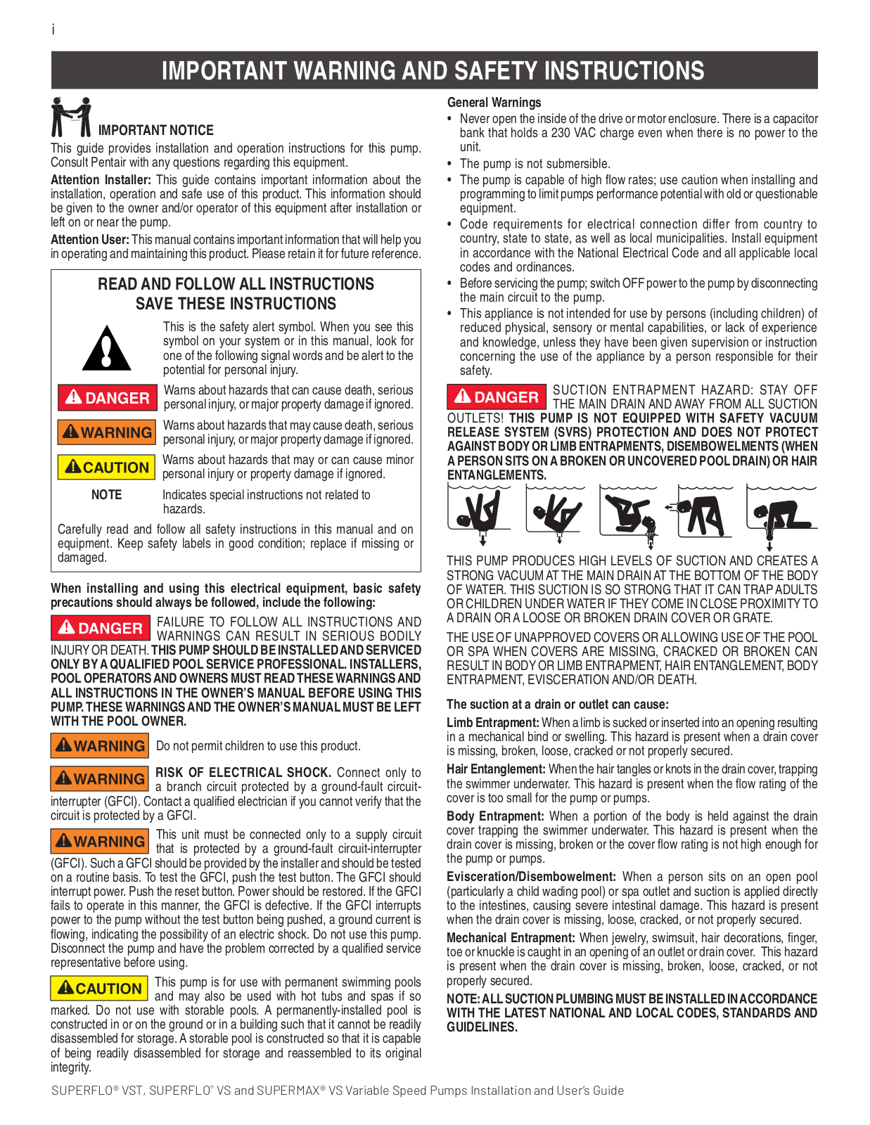
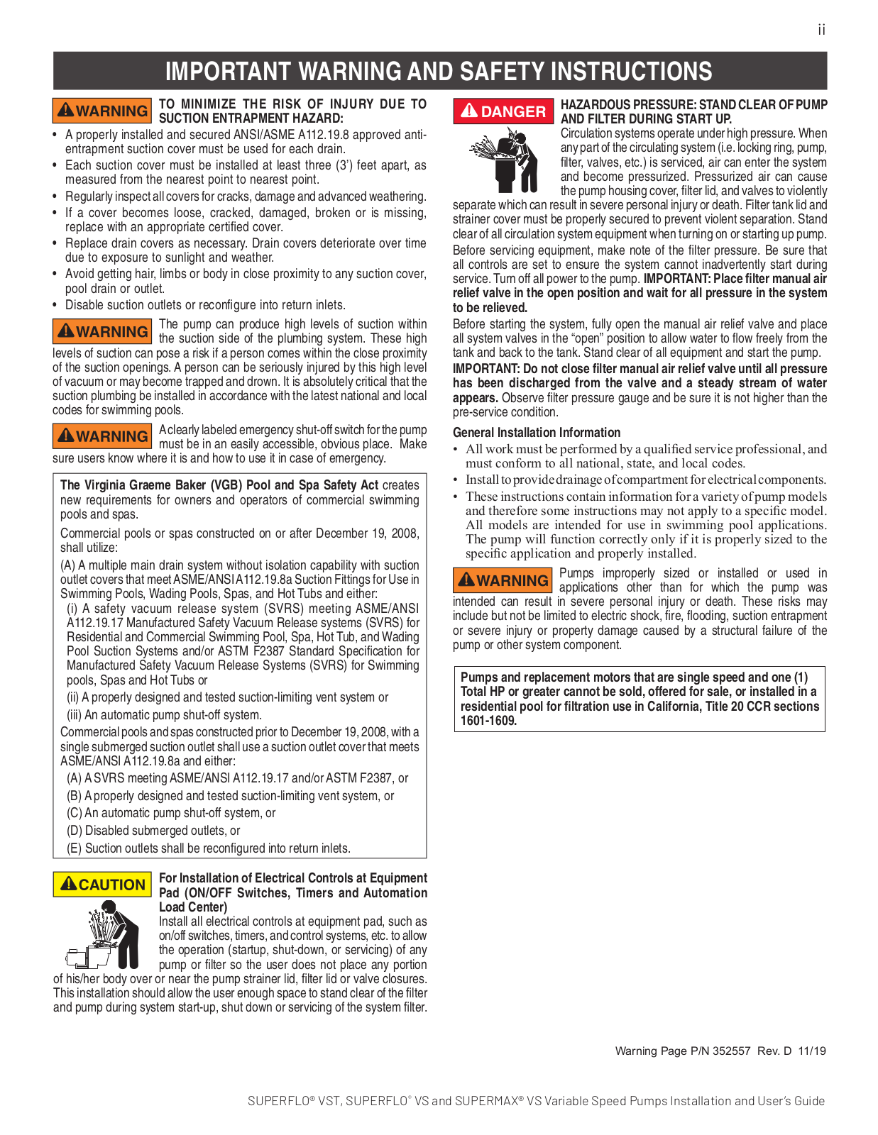
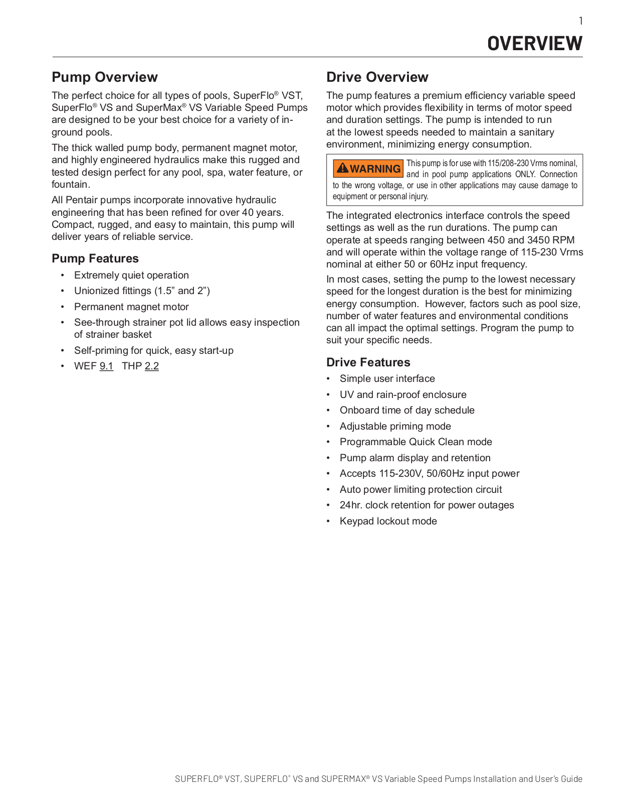
SuperFlo VS
2
SUPERFLO VS STA-RITE
SUPERFLO VST
SuperMax
2
SUPERMAX VS
SW5P6R
SWEEP I
SWEEP II
Swimming Pool Filter
Swimming Pool Pump
2
T
T20
T20 T-Series
t29
T40-B
T43
T50 T-SERIES
T53
T531926G Series
Tagelus
3
TAGELUS II
Tagelus TA 100D
Tagelus TA 40
Tagelus TA 40D
Tagelus TA 50
Tagelus TA 50D
Tagelus TA 60D
TAURUS VS
TE090624010
TE090624011
TE121024010
TE121024011
TE121024020
TE121048010
TE121048020
TE162024010
TE162024011
TE162024020
TE162048010
TE162048020
ThermalFlo
ThermalFlo 1200R H/C
ThermalFlo Heat Pump Contol Panel Addendum
ThermalFLo HP
ThermalFlo HP 1200
2
ThermalFlo HP 1200R
ThermalFlo HP 1200R H/C
ThermalFlo HP 500
2
ThermalFlo HP 700
2
ThermalFlo HP 900
2
T-Series T15
Loading...
Loading...
Nothing found
SuperFlo VS
Installation Manual
148 pgs
9.76 Mb
0
User Manual
27 pgs
5.07 Mb
0
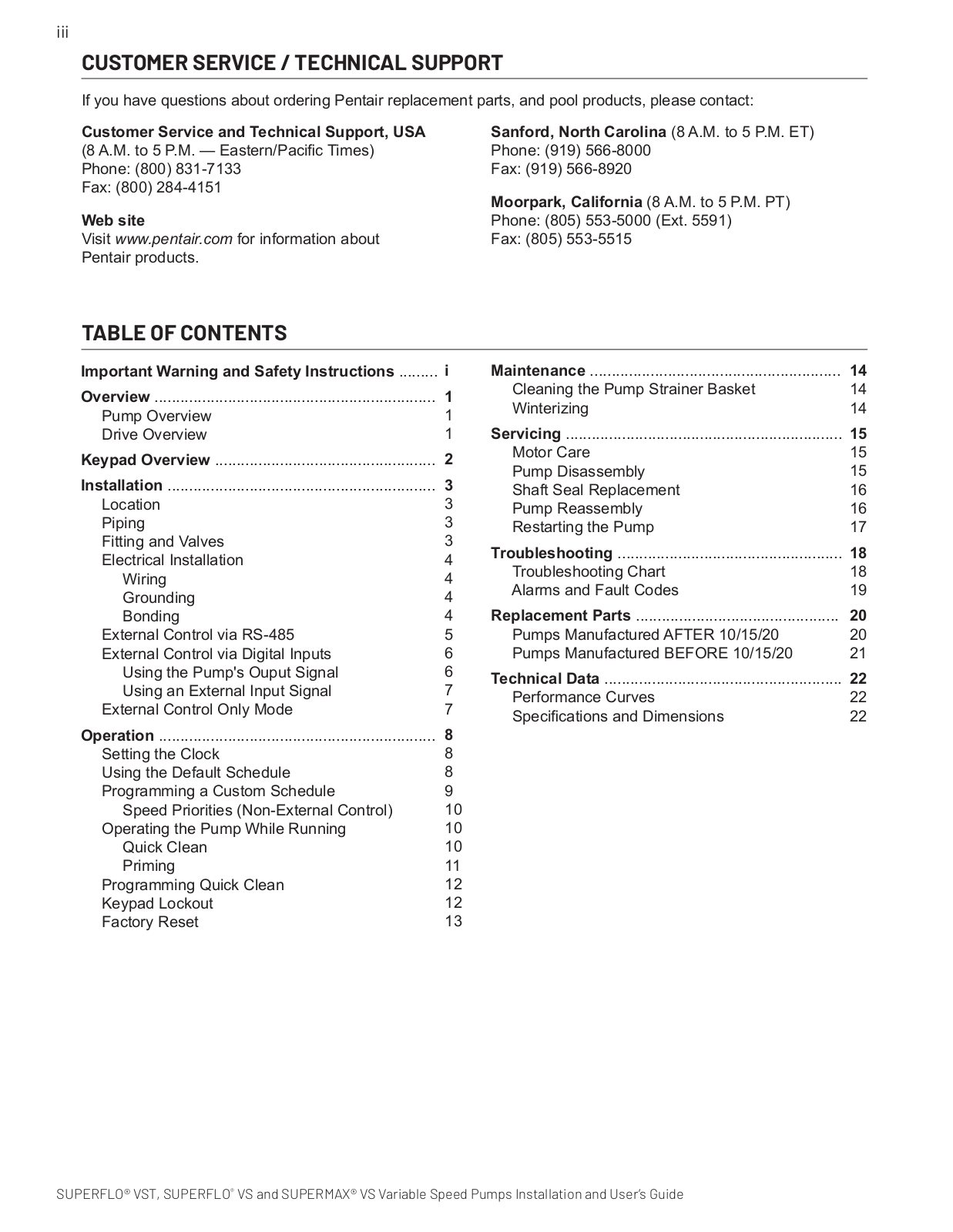
Table of contents
Loading...
Pentair SuperFlo VS User Manual
...
Pentair User Manual
Download
Specifications and Main Features
Frequently Asked Questions
User Manual
Download
Loading...
+
18
hidden pages
Unhide
You need points to download manuals.
1 point = 1 manual.
You can buy points or you can get point for every manual you upload.
Buy points
Upload your manuals
 Loading...