

DYNA-PRO®
SELF-PRIMING POOL/SPA PUMP
IMPORTANT SAFETY INSTRUCTIONS
READ AND FOLLOW ALL INSTRUCTIONS
SAVE THESE INSTRUCTIONS
INSTALLATION AND
USER’S GUIDE
i
CUSTOMER SERVICE / TECHNICAL SUPPORT
If you have questions about ordering Pentair Aquatic Systems replacement parts, and pool products, please contact:
Customer Service and Technical Support, USA
(8 A.M. to 4:30 P.M. — Eastern/Pacific Times)
Phone: (800) 831-7133
Fax: (800) 284-4151
Web site
Visit www.pentairpool.com or www.staritepool.com for
information about Pentair products.
TABLE OF CONTENTS
Important Pump Warning and
Safety Instructions ................................................
Installation ..............................................................
Location
Piping
Taping Instructions
Fittings
Pump Suction Requirements
Suction Outlet Covers
Testing and Certification
Water Velocity
Electrical Installation
Wiring
Grounding
Bonding
Sanford, North Carolina (8 A.M. to 4:30 P.M. ET)
Phone: (919) 566-8000
Fax: (919) 566-8920
Moorpark, California (8 A.M. to 4:30 P.M. PT)
Phone: (805) 553-5000 (Ext. 5591)
Fax: (805) 553-5515
Operation ...............................................................
ii
1
1
1
1
1
2
2
2
2
3
3
3
3
Pressure Test
Priming the Pump
Draining the Pump
Winterizing
Start-up for Winterized Equipment
Maintenance ..........................................................
Cleaning the Strainer Basket
Pump Disassembly / Removing Old Seal
Pump Reassembly / Installing New Seal
Troubleshooting ....................................................
Replacement Parts ...............................................
Motor Table
Parts List
4
4
4
4
4
5
6
6
6
7
8
9
9
10
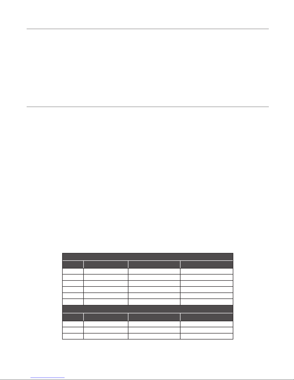
HP MPRA Series MPE Series MPEA Series
1/2 MPE6C-204L
3/4 MPRA6D-204L MPE6D-205L MPEA6D-204L
1 MPRA6E-205L MPE6E-206L MPEA6E-205L
1-1/2 MPEA6F-206L
2 MPE6G-208L MPEA6G-207L
2-1/2 MPEAA6G-208L
HP MPRA Series MPE Series MPEA Series
1-1/2 MPRA6YF-206L
2 MPE6YG-208L
2-1/2 MPEAA6YG-208L
P/N S771 Rev. E 7/19/18
DYNAPRO® Self-Priming Pool/Spa Pump Installation and User’s Guide
Pump Models
SINGLE SPEED MODELS
TWO SPEED MODELS
IMPORTANT PUMP WARNING AND SAFETY INSTRUCTIONS
F
IMPORTANT NOTICE
This guide provides installation and operation instructions for this pump.
Consult Pentair with any questions regarding this equipment.
Attention Installer: This guide contains important information about the
installation, operation and safe use of this product. This information should
be given to the owner and/or operator of this equipment after installation
or left on or near the pump.
Attention User: This manual contains important information that will help
you in operating and maintaining this product. Please retain it for future
reference.
READ AND FOLLOW ALL INSTRUCTIONS
SAVE THESE INSTRUCTIONS
This is the safety alert symbol. When you see this
symbol on your system or in this manual, look for
one of the following signal words and be alert to
the potential for personal injury.
Warns about hazards that can cause death,
serious personal injury, or major property damage
if ignored.
Warns about hazards that may cause death,
serious personal injury, or major property damage
if ignored.
Warns about hazards that may or can cause minor
personal injury or property damage
if ignored.
NOTE Indicates special instructions not related to
hazards.
Carefully read and follow all safety instructions in this manual and on
equipment. Keep safety labels in good condition; replace if missing
or damaged.
When installing and using this electrical equipment, basic safety
precautions should always be followed, include the following:
Do not permit children to use this product.
RISK OF ELECTRICAL SHOCK. Connect only to
a branch circuit protected by a ground-fault circuitinterrupter (GFCI). Contact a qualified electrician if you cannot verify that
the circuit is protected by a GFCI.
This unit must be connected only to a supply circuit
that is protected by a ground-fault circuit-interrupter
(GFCI). Such a GFCI should be provided by the installer and should
be tested on a routine basis. To test the GFCI, push the test button.
The GFCI should interrupt power. Push the reset button. Power should
be restored. If the GFCI fails to operate in this manner, the GFCI is
defective. If the GFCI interrupts power to the pump without the test button
being pushed, a ground current is flowing, indicating the possibility of an
electric shock. Do not use this pump. Disconnect the pump and have the
problem corrected by a qualified service representative before using.
This pump is for use with permanent swimming
pools and may also be used with hot tubs and spas
if so marked. Do not use with storable pools. A permanently-installed pool
is constructed in or on the ground or in a building such that it cannot be
readily disassembled for storage. A storable pool is constructed so that
it is capable of being readily disassembled for storage and reassembled
to its original integrity.
ii
General Warnings
• Never open the inside of the drive motor enclosure. There is a
capacitor bank that holds a 230 VAC charge even when there is no
power to the unit.
• The pump is not submersible.
• The pump is capable of high flow rates; use caution when installing
and programming to limit pumps performance potential with old or
questionable equipment.
• Code requirements for electrical connection differ from country to
country, state to state, as well as local municipalities. Install equipment
in accordance with the National Electrical Code and all applicable
local codes and ordinances.
• Before servicing the pump; switch OFF power to the pump by
disconnecting the main circuit to the pump.
• This appliance is not intended for use by persons (including children) of
reduced physical, sensory or mental capabilities, or lack of experience
and knowledge, unless they have been given supervision or instruction
concerning the use of the appliance by a person responsible for their
safety.
FAILURE TO FOLLOW ALL INSTRUCTIONS AND
WARNINGS CAN RESULT IN SERIOUS BODILY
INJURY OR DEATH. THIS PUMP SHOULD BE INSTALLED AND
SERVICED ONLY BY A QUALIFIED POOL SERVICE PROFESSIONAL.
INSTALLERS, POOL OPERATORS AND OWNERS MUST READ
THESE WARNINGS AND ALL INSTRUCTIONS IN THE OWNER’S
MANUAL BEFORE USING THIS PUMP. THESE WARNINGS AND
THE OWNER’S MANUAL MUST BE LEFT WITH THE POOL OWNER.
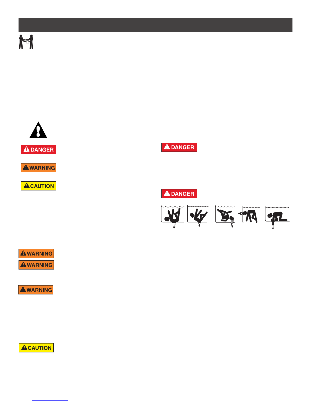
SUCTION ENTRAPMENT HAZARD: STAY OFF
THE MAIN DRAIN AND AWAY FROM ALL SUCTION
OUTLETS!
THIS PUMP PRODUCES HIGH LEVELS OF SUCTION AND CREATES
A STRONG VACUUM AT THE MAIN DRAIN AT THE BOTTOM OF THE
BODY OF WATER. THIS SUCTION IS SO STRONG THAT IT CAN TRAP
ADULTS OR CHILDREN UNDER WATER IF THEY COME IN CLOSE
PROXIMITY TO A DRAIN OR A LOOSE OR BROKEN DRAIN COVER
OR GRATE.
THE USE OF UNAPPROVED COVERS OR ALLOWING USE OF
THE POOL OR SPA WHEN COVERS ARE MISSING, CRACKED OR
BROKEN CAN RESULT IN BODY OR LIMB ENTRAPMENT, HAIR
ENTANGLEMENT, BODY ENTRAPMENT, EVISCERATION AND/OR
DEATH.
The suction at a drain or outlet can cause:
Limb Entrapment: When a limb is sucked or inserted into an opening
resulting in a mechanical bind or swelling. This hazard is present when
a drain cover is missing, broken, loose, cracked or not properly secured.
Hair Entanglement: When the hair tangles or knots in the drain cover,
trapping the swimmer underwater. This hazard is present when the flow
rating of the cover is too small for the pump or pumps.
Body Entrapment: When a portion of the body is held against the drain
cover trapping the swimmer underwater. This hazard is present when the
drain cover is missing, broken or the cover flow rating is not high enough
for the pump or pumps.
Evisceration/Disembowelment: When a person sits on an open pool
(particularly a child wading pool) or spa outlet and suction is applied directly
to the intestines, causing severe intestinal damage. This hazard is present
when the drain cover is missing, loose, cracked, or not properly secured.
DYNAPRO® Self-Priming Pool/Spa Pump Installation and User’s Guide
iii
IMPORTANT PUMP WARNING AND SAFETY INSTRUCTIONS
Mechanical Entrapment: When jewelry, swimsuit, hair decorations, finger,
toe or knuckle is caught in an opening of an outlet or drain cover. This
hazard is present when the drain cover is missing, broken, loose, cracked,
or not properly secured.
NOTE: ALL SUCTION PLUMBING MUST BE INSTALLED IN
ACCORDANCE WITH THE LATEST NATIONAL AND LOCAL CODES,
STANDARDS AND GUIDELINES.
TO MINIMIZE THE RISK OF INJURY DUE TO
SUCTION ENTRAPMENT HAZARD:
• A properly installed and secured ANSI/ASME A112.19.8 approved
anti-entrapment suction cover must be used for each drain.
• Each suction cover must be installed at least three (3’) feet apart, as
measured from the nearest point to nearest point.
• Regularly inspect all covers for cracks, damage and advanced
weathering.
• If a cover becomes loose, cracked, damaged, broken or is missing,
replace with an appropriate certified cover.
• Replace drain covers as necessary. Drain covers deteriorate over
time due to exposure to sunlight and weather.
• Avoid getting hair, limbs or body in close proximity to any suction
cover, pool drain or outlet.
• Disable suction outlets or reconfigure into return inlets.
A clearly labeled emergency shut-off switch for the
pump must be in an easily accessible, obvious place.
Make sure users know where it is and how to use it in case of emergency.
The Virginia Graeme Baker (VGB) Pool and Spa Safety Act creates
new requirements for owners and operators of commercial swimming
pools and spas.
Commercial pools or spas constructed on or after December 19, 2008,
shall utilize:
(A) A multiple main drain system without isolation capability with suction
outlet covers that meet ASME/ANSI A112.19.8a Suction Fittings for
Use in Swimming Pools, Wading Pools, Spas, and Hot Tubs and either:
(i) A safety vacuum release system (SVRS) meeting ASME/ANSI
A112.19.17 Manufactured Safety Vacuum Release systems (SVRS)
for Residential and Commercial Swimming Pool, Spa, Hot Tub,
and Wading Pool Suction Systems and/or ASTM F2387 Standard
Specification for Manufactured Safety Vacuum Release Systems
(SVRS) for Swimming pools, Spas and Hot Tubs or
(ii) A properly designed and tested suction-limiting vent system or
(iii) An automatic pump shut-off system.
Commercial pools and spas constructed prior to December 19, 2008,
with a single submerged suction outlet shall use a suction outlet cover
that meets ASME/ANSI A112.19.8a and either:
(A) A SVRS meeting ASME/ANSI A112.19.17 and/or ASTM F2387, or
(B) A properly designed and tested suction-limiting vent system, or
(C) An automatic pump shut-off system, or
(D) Disabled submerged outlets, or
(E) Suction outlets shall be reconfigured into return inlets.
For Installation of Electrical Controls at Equipment Pad (ON/OFF
Switches, Timers and Automation Load Center)
Install all electrical controls at equipment pad, such as
on/off switches, timers, and control systems, etc. to
allow the operation (startup, shut-down, or servicing)
of any pump or filter so the user does not place any
portion of his/her body over or near the pump strainer
lid, filter lid or valve closures. This installation should
allow the user enough space to stand clear of the filter
and pump during system start-up, shut down or servicing of the system filter.
DYNAPRO® Self-Priming Pool/Spa Pump Installation and User’s Guide
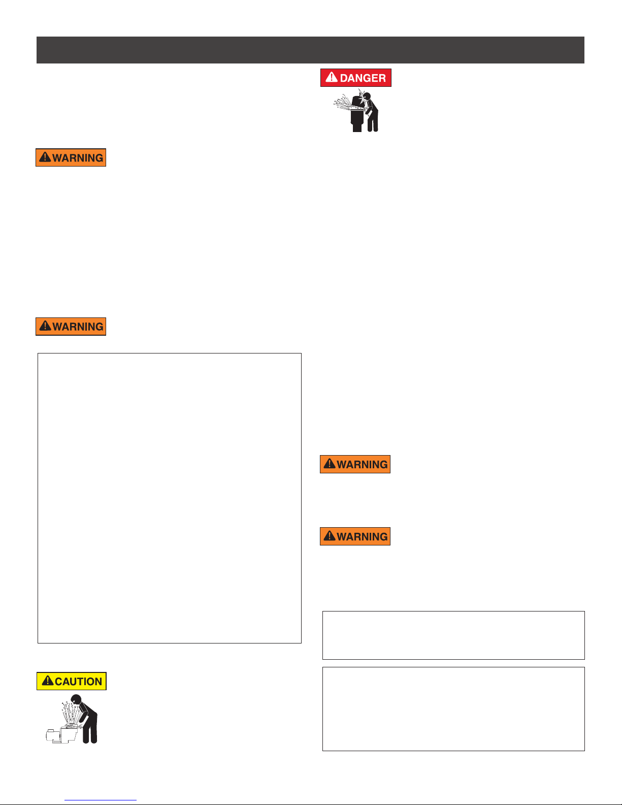
HAZARDOUS PRESSURE: STAND CLEAR OF
PUMP AND FILTER DURING START UP
Circulation systems operate under high pressure.
When any part of the circulating system (i.e.
locking ring, pump, filter, valves, etc.) is serviced,
air can enter the system and become pressurized.
Pressurized air can cause the pump housing cover, filter lid, and valves
to violently separate which can result in severe personal injury or death.
Filter tank lid and strainer cover must be properly secured to prevent
violent separation. Stand clear of all circulation system equipment when
turning on or starting up pump.
Before servicing equipment, make note of the filter pressure. Be sure
that all controls are set to ensure the system cannot inadvertently start
during service. Turn off all power to the pump. IMPORTANT: Place filter
manual air relief valve in the open position and wait for all pressure
in the system to be relieved.
Before starting the system, fully open the manual air relief valve and place
all system valves in the “open” position to allow water to flow freely from the
tank and back to the tank. Stand clear of all equipment and start the pump.
IMPORTANT: Do not close filter manual air relief valve until all
pressure has been discharged from the valve and a steady stream
of water appears. Observe filter pressure gauge and be sure it is not
higher than the pre-service condition.
General Installation Information
• All work must be performed by a qualified service professional, and
must conform to all national, state, and local codes.
• Install to provide drainage of compartment for electrical components.
• These instructions contain information for a variety of pump models
and therefore some instructions may not apply to a specific model. All
models are intended for use in swimming pool applications. The pump
will function correctly only if it is properly sized to the specific application
and properly installed.
Pumps improperly sized or installed or used in
applications other than for which the pump was
intended can result in severe personal injury or death. These risks
may include but not be limited to electric shock, fire, flooding, suction
entrapment or severe injury or property damage caused by a structural
failure of the pump or other system component.
The pump can produce high levels of suction within
the suction side of the plumbing system. These
high levels of suction can pose a risk if a person comes within the close
proximity of the suction openings. A person can be seriously injured
by this high level of vacuum or may become trapped and drown. It is
absolutely critical that the suction plumbing be installed in accordance
with the latest national and local codes for swimming pools.
Pumps and replacement motors that are single speed and
one (1) Total HP or greater cannot be sold, offered for sale, or
installed in a residential pool for filtration use in California, Title
20 CCR sections 1601-1609.
Warnings and safety instructions for Pentair Aquatic Systems pumps
and other related products are available at:
http://www.pentairpool.com/pool-owner/safety-warnings/ or call
(800) 831-7133 for additional free copies of these instructions.
Please refer to http://www.pentairpool.com/pool-owner/safety-
warnings/ for warning and safety instructions related to the this
product.
Warning Page P/N 352557 Rev. C 7/18
INSTALLATION
Trapped air in the system can cause permanent equipment damage. Ensure all air is relieved from the system
before operating, testing or servicing the equipment.
Do NOT connect system to a high pressure or city water system.
1
Location
Only qualified, licensed personnel should install the pump
and pump wiring.
Be sure the Dyna-Pro® Self-Priming Pool/Spa Pump
equipment pad or plumbing meets the following
requirements:
• Pump mount must be solid, level, rigid and
minimize vibration. To reduce vibration and stress
to piping, bolt the pump to the equipment pad.
• Allow for enough ventilation to maintain air
temperature at less than the maximum ambient
temperature rating listed on the motor nameplate.
• If installed in an enclosure/pump house, the
enclosure must have adequate ventilation and
air circulation to keep the temperature inside the
enclosure at or below the maximum rated ambient
temperature when the pump is running.
• Locate away from corrosive or flammable liquids.
• Suction port should be as close to water level as
possible. This pump will not lift water more than 10
ft. (3m).
• To reduce friction losses use short, straight suction
pipe.
• Allow for gate valves in both the suction and
discharge piping.
• Provide adequate floor drainage to prevent flooding
and protect the pump from excess moisture.
• Allow adequate access for servicing pump and
piping.
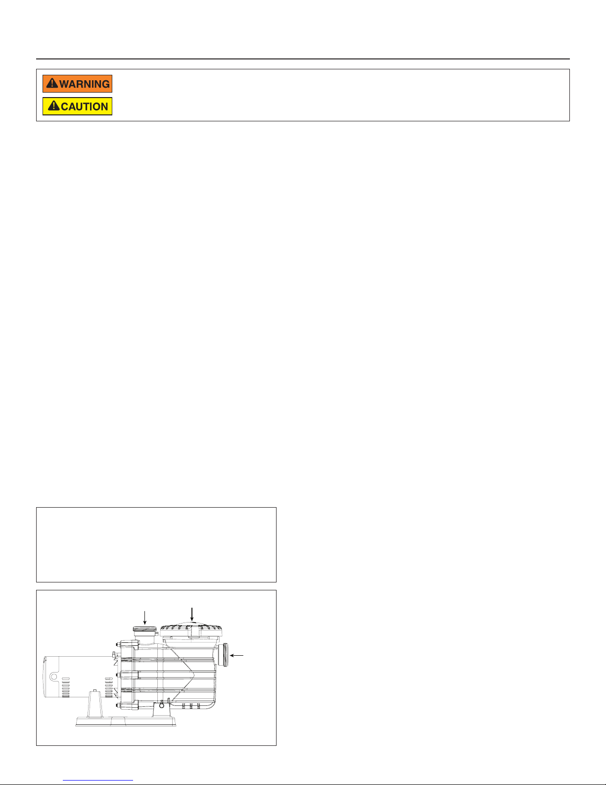
Port Threads:
Internal - 2” NPT for direct connection to pipe. External
- 3” Buttress. Fits Sta-Rite 38405-4094 Union Collar for
quick disconnect.
Order: Union Kit #77703-0105 (1.5” and 2” Union Halves).
Figure 1
Discharge
Port
Strainer
Pot Lid
Piping
1. Use at least 2” (51mm) pipe. Increase size if a long run is needed.
2. Support both the suction and discharge piping independently,
placing these supports as close to the pump as possible. This will
prevent unnecessary strain on the pump.
3. During piping installation, start all piping and run the pipe away
from the pump. This will prevent strain caused by a gap at the last
connection.
4. Slope suction pipe slightly upward toward the pump to prevent
airlocking.
5. To prevent flooding when removing the pump for service, all
flooded suction systems must have a gate valve in both the
suction and discharge pipes.
6. For most installations Pentair recommends installing a valve
on both the pump suction and return lines so that the pump
can be isolated during routine maintenance. However, we also
recommend a valve, elbow or tee installed in the suction line
should be no closer to the front of the pump than five (5) times
the suction line diameter.
Example: A 2 inch pipe requires a 10 inch (25.4 cm) straight run
in front of the suction inlet of the pump. This will help the pump
prime faster and last longer.
Note: Do not install 90° elbows directly into the pump inlet or
outlet.
Taping Instructions
1. If connecting threaded pipe directly to the pump, apply one or
two layers of thread seal tape to the male pipe threads. Cover the
entire threaded portion of the pipe.
Note: Do NOT use pipe dope; pipe dope can lead to cracking in
some plastics and may damage components in the piping system.
2. If plumbing threaded pipe to the pump using unions, apply thread
seal tape between the pipe and union adapter. The union collar
should be installed hand-tight. Be sure the union’s O-ring is
seated correctly in its groove.
Note: DO NOT overtighten or tighten past the thread stops within
the pump ports.
If leaks occur, remove pipe, clean off old tape, rewrap with one or two
layers of new tape and reinstall the piping.
Pump may be bolted to level
foundation or mounting bracket
Suction
Port
Fittings
1. Fittings restrict flow. Use the fewest number of fittings possible to
maximize system efficiency.
2. Avoid fittings that could lead to air traps in suction piping.
3. Pool and spa drains must conform to International Association of
Plumbing and Mechanical Officials (IAPMO) standards.
4. Use only non-entrapping suction fittings and dual suction outlets.
DYNA-PRO® Self-Priming Pool/Spa Pump Installation and User’s Guide
 Loading...