

Pentair INTELLIFLO VSF, STA-RITE INTELLIFLOXF, STA-RITE INTELLIPROXF VSF Installation And User Manual
INTELLIFLO® VSF
VARIABLE SPEED AND FLOW PUMP
IMPORTANT SAFETY INSTRUCTIONS
READ AND FOLLOW ALL INSTRUCTIONS
SAVE THESE INSTRUCTIONS
INSTALLATION AND
USER’S GUIDE

i
CUSTOMER SERVICE / TECHNICAL SUPPORT
If you have questions about ordering Pentair Aquatic Systems replacement parts, and pool products, please contact:
Customer Service and Technical Support, USA
(8 A.M. to 4:30 P.M. — Eastern/Pacific Times)
Phone: (800) 831-7133
Fax: (800) 284-4151
Web site
Visit www.pentairpool.com or www.staritepool.com for
information about Pentair products.*
TABLE OF CONTENTS
Important Pump Warning and
Safety Instructions ................................................
Pump Overview ......................................................
Drive Assembly and Control Panel
External Control
Motor Features
Drive Features
Installation ..............................................................
Location
Piping
Electrical Requirements
Optional Keypad Relocation Kit
Fittings and Valves
Electrical Installation
Wiring, Grounding and Bonding
Connecting to an Automation System
Operating the Pump ..............................................
Priming the Pump
Using the Operator Control Panel
Stopping and Starting the Pump
Adjusting and Saving a Pump Speed/Flow
Operating the Pump at Preset Speeds
Pump Operating Modes
Program Types
Control Panel: Pump Menu Guide
Pump Settings .......................................................
Set Date and Time
Set AM/PM or 24-Hour Clock
Set Min/Max Speeds
Set Min/Max Flow Rates
Set Flow Limit for Speed Program
Set Maximum System Pressure
Set Pressure Limit for Speed Program
Pump Address
Set Screen Contrast
Set Control Panel Language
Set Temperature Unit
Password Protection
Setting Password
Set Ramping Rate
Sanford, North Carolina (8 A.M. to 4:30 P.M. ET)
Phone: (919) 566-8000
Fax: (919) 566-8920
Moorpark, California (8 A.M. to 4:30 P.M. PT)
Phone: (805) 553-5000 (Ext. 5591)
Fax: (805) 553-5515
Setting Programs 1-8 ............................................
ii
1
1
1
1
1
2
2
2
2
2
2
3
3
4
5
5
6
7
7
7
7
7
8
10
10
10
10
10
11
11
12
12
12
12
12
13
13
13
Pump Operating Modes
Set Programs 1-4 in Manual Mode
Set Programs 1-4 in Egg-Timer Mode
Set Programs 1-8 in Schedule Mode
External Control ....................................................
Features .................................................................
Time Out
Quick Clean/Only High Speed Override Feature
Priming ..................................................................
Priming Features
Setting Priming Features
Disabling Priming with an Automation System
Thermal Mode .......................................................
Maintenance ..........................................................
Pump Strainer Basket
Cleaning the Pump Strainer Basket
Winterizing
Servicing ...............................................................
Motor and Drive Care
Shaft Seal Replacement
Pump Disassembly
Pump Reassembly
Drive Assembly Removal and Installation
Troubleshooting ....................................................
Alerts and Warnings
Troubleshooting Chart
Replacement Parts ...............................................
Technical Data .......................................................
Pump Dimensions
Electrical Specifications
Pump Performance Curves
Operator Control Panel Quick Reference Guide
14
14
14
14
15
16
17
17
17
17
18
19
19
20
21
21
21
21
22
22
22
22
23
23
25
25
26
28
29
29
29
29
30
* Translated versions of this manual are available online at / La versión en español de este manual del producto, se puede encontrar en línea a /
La version française de ce manuel est disponible à
P/N 356652 Rev. D 2/22/18
INTELLIFLO® VSF Variable Speed and Flow Pump Installation and User’s Guide
: https://pentairpool.com/en/products/pumps/intelliflo%20vsf#resources
IMPORTANT PUMP WARNING AND SAFETY INSTRUCTIONS
F
IMPORTANT NOTICE
This guide provides installation and operation instructions for this pump.
Consult Pentair with any questions regarding this equipment.
Attention Installer: This guide contains important information about the
installation, operation and safe use of this product. This information should
be given to the owner and/or operator of this equipment after installation
or left on or near the pump.
Attention User: This manual contains important information that will help
you in operating and maintaining this product. Please retain it for future
reference.
READ AND FOLLOW ALL INSTRUCTIONS
SAVE THESE INSTRUCTIONS
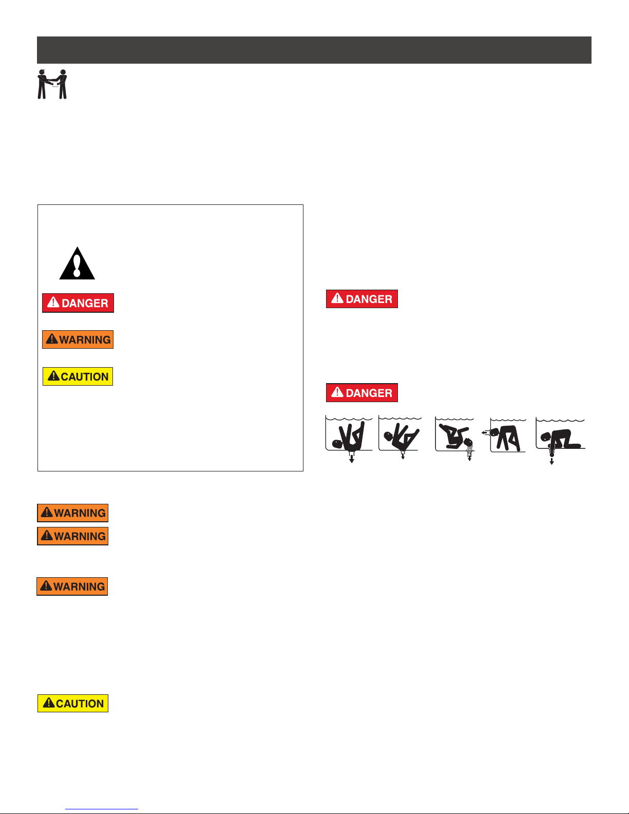
This is the safety alert symbol. When you see this
symbol on your system or in this manual, look for
one of the following signal words and be alert to
the potential for personal injury.
Warns about hazards that can cause death,
serious personal injury, or major property damage
if ignored.
Warns about hazards that may cause death,
serious personal injury, or major property damage
if ignored.
Warns about hazards that may or can cause minor
personal injury or property damage
if ignored.
NOTE Indicates special instructions not related to
hazards.
Carefully read and follow all safety instructions in this manual and on
equipment. Keep safety labels in good condition; replace if missing
or damaged.
When installing and using this electrical equipment, basic safety
precautions should always be followed, include the following:
Do not permit children to use this product.
RISK OF ELECTRICAL SHOCK. Connect only to
a branch circuit protected by a ground-fault circuitinterrupter (GFCI). Contact a qualified electrician if you cannot verify that
the circuit is protected by a GFCI.
This unit must be connected only to a supply circuit
that is protected by a ground-fault circuit-interrupter
(GFCI). Such a GFCI should be provided by the installer and should
be tested on a routine basis. To test the GFCI, push the test button.
The GFCI should interrupt power. Push the reset button. Power should
be restored. If the GFCI fails to operate in this manner, the GFCI is
defective. If the GFCI interrupts power to the pump without the test button
being pushed, a ground current is flowing, indicating the possibility of an
electric shock. Do not use this pump. Disconnect the pump and have the
problem corrected by a qualified service representative before using.
This pump is for use with permanent swimming
pools and may also be used with hot tubs and spas
if so marked. Do not use with storable pools. A permanently-installed pool
is constructed in or on the ground or in a building such that it cannot be
readily disassembled for storage. A storable pool is constructed so that
it is capable of being readily disassembled for storage and reassembled
to its original integrity.
ii
General Warnings
• Never open the inside of the drive motor enclosure. There is a
capacitor bank that holds a 230 VAC charge even when there is no
power to the unit.
• The pump is not submersible.
• The pump is capable of high flow rates; use caution when installing
and programming to limit pumps performance potential with old or
questionable equipment.
• Code requirements for electrical connection differ from country to
country, state to state, as well as local municipalities. Install equipment
in accordance with the National Electrical Code and all applicable
local codes and ordinances.
• Before servicing the pump; switch OFF power to the pump by
disconnecting the main circuit to the pump.
• This appliance is not intended for use by persons (including children) of
reduced physical, sensory or mental capabilities, or lack of experience
and knowledge, unless they have been given supervision or instruction
concerning the use of the appliance by a person responsible for their
safety.
FAILURE TO FOLLOW ALL INSTRUCTIONS AND
WARNINGS CAN RESULT IN SERIOUS BODILY
INJURY OR DEATH. THIS PUMP SHOULD BE INSTALLED AND
SERVICED ONLY BY A QUALIFIED POOL SERVICE PROFESSIONAL.
INSTALLERS, POOL OPERATORS AND OWNERS MUST READ
THESE WARNINGS AND ALL INSTRUCTIONS IN THE OWNER’S
MANUAL BEFORE USING THIS PUMP. THESE WARNINGS AND
THE OWNER’S MANUAL MUST BE LEFT WITH THE POOL OWNER.
SUCTION ENTRAPMENT HAZARD: STAY OFF
THE MAIN DRAIN AND AWAY FROM ALL SUCTION
OUTLETS!
THIS PUMP PRODUCES HIGH LEVELS OF SUCTION AND CREATES
A STRONG VACUUM AT THE MAIN DRAIN AT THE BOTTOM OF THE
BODY OF WATER. THIS SUCTION IS SO STRONG THAT IT CAN TRAP
ADULTS OR CHILDREN UNDER WATER IF THEY COME IN CLOSE
PROXIMITY TO A DRAIN OR A LOOSE OR BROKEN DRAIN COVER
OR GRATE.
THE USE OF UNAPPROVED COVERS OR ALLOWING USE OF
THE POOL OR SPA WHEN COVERS ARE MISSING, CRACKED OR
BROKEN CAN RESULT IN BODY OR LIMB ENTRAPMENT, HAIR
ENTANGLEMENT, BODY ENTRAPMENT, EVISCERATION AND/OR
DEATH.
The suction at a drain or outlet can cause:
Limb Entrapment: When a limb is sucked or inserted into an opening
resulting in a mechanical bind or swelling. This hazard is present when
a drain cover is missing, broken, loose, cracked or not properly secured.
Hair Entanglement: When the hair tangles or knots in the drain cover,
trapping the swimmer underwater. This hazard is present when the flow
rating of the cover is too small for the pump or pumps.
Body Entrapment: When a portion of the body is held against the drain
cover trapping the swimmer underwater. This hazard is present when the
drain cover is missing, broken or the cover flow rating is not high enough
for the pump or pumps.
Evisceration/Disembowelment: When a person sits on an open pool
(particularly a child wading pool) or spa outlet and suction is applied directly
to the intestines, causing severe intestinal damage. This hazard is present
when the drain cover is missing, loose, cracked, or not properly secured.
INTELLIFLO® VSF Variable Speed and Flow Pump Installation and User’s Guide
iii
IMPORTANT PUMP WARNING AND SAFETY INSTRUCTIONS
Mechanical Entrapment: When jewelry, swimsuit, hair decorations, finger,
toe or knuckle is caught in an opening of an outlet or drain cover. This
hazard is present when the drain cover is missing, broken, loose, cracked,
or not properly secured.
NOTE: ALL SUCTION PLUMBING MUST BE INSTALLED IN
ACCORDANCE WITH THE LATEST NATIONAL AND LOCAL CODES,
STANDARDS AND GUIDELINES.
TO MINIMIZE THE RISK OF INJURY DUE TO
SUCTION ENTRAPMENT HAZARD:
• A properly installed and secured ANSI/ASME A112.19.8 approved
anti-entrapment suction cover must be used for each drain.
• Each suction cover must be installed at least three (3’) feet apart,
as measured from the nearest point to nearest point.
• Regularly inspect all covers for cracks, damage and advanced
weathering.
• If a cover becomes loose, cracked, damaged, broken or is missing,
replace with an appropriate certified cover.
• Replace drain covers as necessary. Drain covers deteriorate over
time due to exposure to sunlight and weather.
• Avoid getting hair, limbs or body in close proximity to any suction
cover, pool drain or outlet.
• Disable suction outlets or reconfigure into return inlets.
A clearly labeled emergency shut-off switch for the
pump must be in an easily accessible, obvious place.
Make sure users know where it is and how to use it in case of emergency.
The Virginia Graeme Baker (VGB) Pool and Spa Safety Act creates
new requirements for owners and operators of commercial swimming
pools and spas.
Commercial pools or spas constructed on or after December 19, 2008,
shall utilize:
(A) A multiple main drain system without isolation capability with suction
outlet covers that meet ASME/ANSI A112.19.8a Suction Fittings for
Use in Swimming Pools, Wading Pools, Spas, and Hot Tubs and either:
(i) A safety vacuum release system (SVRS) meeting ASME/ANSI
A112.19.17 Manufactured Safety Vacuum Release systems (SVRS)
for Residential and Commercial Swimming Pool, Spa, Hot Tub,
and Wading Pool Suction Systems and/or ASTM F2387 Standard
Specification for Manufactured Safety Vacuum Release Systems
(SVRS) for Swimming pools, Spas and Hot Tubs or
(ii) A properly designed and tested suction-limiting vent system or
(iii) An automatic pump shut-off system.
Commercial pools and spas constructed prior to December 19, 2008,
with a single submerged suction outlet shall use a suction outlet cover
that meets ASME/ANSI A112.19.8a and either:
(A) A SVRS meeting ASME/ANSI A112.19.17 and/or ASTM F2387, or
(B) A properly designed and tested suction-limiting vent system, or
(C) An automatic pump shut-off system, or
(D) Disabled submerged outlets, or
(E) Suction outlets shall be reconfigured into return inlets.
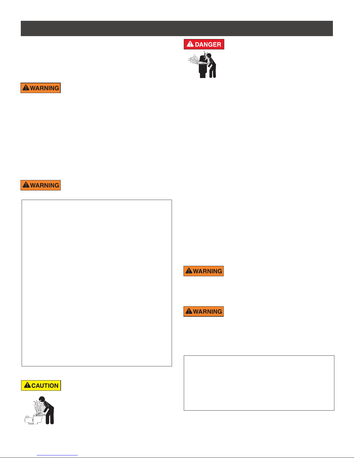
For Installation of Electrical Controls at Equipment Pad (ON/OFF
Switches, Timers and Automation Load Center)
Install all electrical controls at equipment pad, such as
on/off switches, timers, and control systems, etc. to
allow the operation (startup, shut-down, or servicing)
of any pump or filter so the user does not place any
portion of his/her body over or near the pump strainer
lid, filter lid or valve closures. This installation should
allow the user enough space to stand clear of the
filter and pump during system start-up, shut down or
servicing of the system filter.
INTELLIFLO® VSF Variable Speed and Flow Pump Installation and User’s Guide
HAZARDOUS PRESSURE: STAND CLEAR OF
PUMP AND FILTER DURING START UP
Circulation systems operate under high pressure.
When any part of the circulating system (i.e.
locking ring, pump, filter, valves, etc.) is serviced,
air can enter the system and become pressurized.
Pressurized air can cause the pump housing cover, filter lid, and valves
to violently separate which can result in severe personal injury or death.
Filter tank lid and strainer cover must be properly secured to prevent
violent separation. Stand clear of all circulation system equipment when
turning on or starting up pump.
Before servicing equipment, make note of the filter pressure. Be sure
that all controls are set to ensure the system cannot inadvertently start
during service. Turn off all power to the pump. IMPORTANT: Place filter
manual air relief valve in the open position and wait for all pressure
in the system to be relieved.
Before starting the system, fully open the manual air relief valve and place
all system valves in the “open” position to allow water to flow freely from the
tank and back to the tank. Stand clear of all equipment and start the pump.
IMPORTANT: Do not close filter manual air relief valve until all
pressure has been discharged from the valve and a steady stream
of water appears. Observe filter pressure gauge and be sure it is not
higher than the pre-service condition.
General Installation Information
• All work must be performed by a qualified service professional, and
must conform to all national, state, and local codes.
• Install to provide drainage of compartment for electrical components.
• These instructions contain information for a variety of pump models
and therefore some instructions may not apply to a specific model. All
models are intended for use in swimming pool applications. The pump
will function correctly only if it is properly sized to the specific application
and properly installed.
Pumps improperly sized or installed or used in
applications other than for which the pump was
intended can result in severe personal injury or death. These risks
may include but not be limited to electric shock, fire, flooding, suction
entrapment or severe injury or property damage caused by a structural
failure of the pump or other system component.
The pump can produce high levels of suction within
the suction side of the plumbing system. These
high levels of suction can pose a risk if a person comes within the close
proximity of the suction openings. A person can be seriously injured
by this high level of vacuum or may become trapped and drown. It is
absolutely critical that the suction plumbing be installed in accordance
with the latest national and local codes for swimming pools.
Warnings and safety instructions for Pentair Aquatic Systems
pumps and other related products are available at:
http://www.pentairpool.com/pool-owner/safety-warnings/ or call
(800) 831-7133 for additional free copies of these instructions.
Please refer to http://www.pentairpool.com/pool-owner/
safety-warnings/ for warning and safety instructions related to the
this product.
SAVE THESE INSTRUCTIONS
Warning Page P/N 352557 Rev. B 9/16
PUMP OVERVIEW
1
The IntelliFlo® VSF Variable Speed and Flow Pump
can be programmed to run at a speed or a constant
flow rate over set time intervals for maximum operating
efficiency and energy conservation for a variety of
inground pools.
• The pump can operate from 450 RPM to 3450 RPM
with four preset speeds of 750, 1500, 2350 and 3110
RPM, or the pump can be set to control its own speed
and maintain a constant flow rate.
• The pump can adapt to applications between 20 and
140 GPM. Simply program the pump to the desired
flow rate, and the pump will automatically adjust to
operating conditions to maintain that specific flow rate.
• Up to 8 customizable programs that can be set for
constant flow or speed in either Manual, Egg Timer
or Schedule modes.
• Pump control panel alarm LED and error messages
warn the user of improper operation.
• Programmable priming mode with automatic detection
of prime for easy start-up and automatic detection of
loss of prime.
• Compatible with most cleaning systems, filters, and
jet action spas.
• UL/CUL/NSF
External Control
Most Pentair automation systems and IntelliComm
Communication Centers can remotely control the
IntelliFlo VSF pump. The pump’s communications
address and other functions are accessible from the
pump’s control panel.
• RS-485 communication cable included
• IntelliComm systems control one IntelliFlo pump using
the 4 External Control programs.
Refer to the automation system manual for further
details on how to connect and use the system with
your variable speed pump.
®
Motor Features
• High Efficiency Permanent Magnet Synchronous
Motor (PMSM)
• Superior speed control
• Operates at lower temperatures due to high
efficiency
• Designed to withstand outdoor environment
• Totally Enclosed Fan Cooled (TEFC) Motor
• 56 Square Flange
• Low noise
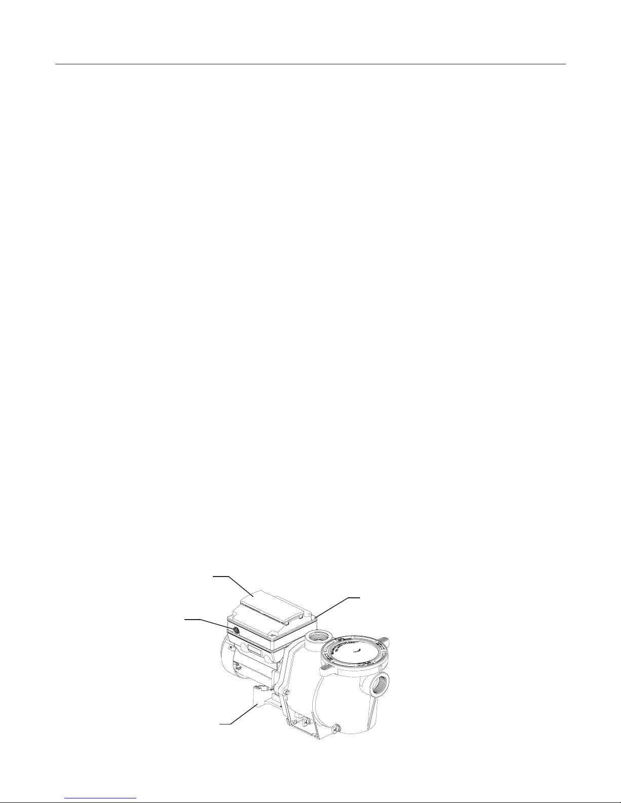
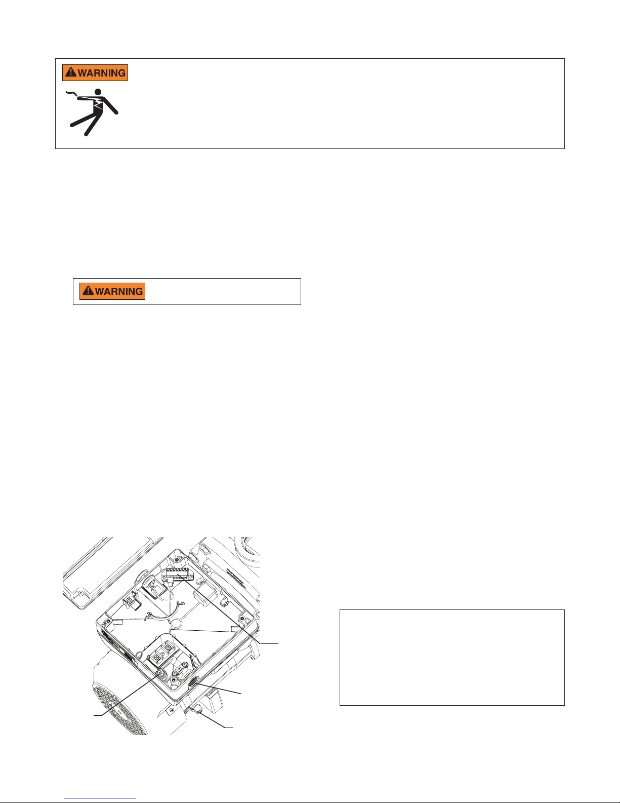
Drive Assembly and Control Panel
The IntelliFlo VSF pump drive is designed to produce
maximum motor operational efficiency. The drive controls
the motor’s rotational speed by controlling the frequency
of the supplied current. It also protects the motor and
pump from operating outside of their intended operating
parameters.
The control panel can be mounted on the pump in four
different directions in order to provide the user the best
access. The control panel can also be mounted in a more
convenient location with the help of the keypad relocation
kit (P/N 356904Z).
Operator Control Panel Cover
Buttons and LED (Beneath)
Strain Relief Port
for Incoming AC Power
Drive Features
• Active Power Factor Correction
• UL 60730 Compliant
• Rotatable Keypad
• Easy Overhead Wiring
• High Drive Operational Efficiency
• Sensorless Flow and Pressure Control
Technology
• Loss of Prime Detection
Communication port for connection
to automation systems or
communication centers via two-wire
RS-485 cable (not shown)
Motor Stand
Variable Speed and Flow Drive Assembly
INTELLIFLO® VSF Variable Speed and Flow Pump Installation and User’s GuideINTELLIFLO

2
3 IN.
(7.6 CM)
MINIMUM
6 IN.
(15.2 CM)
MINIMUM
MIN 5 X SUCTION PIPE DIAMETER
ELBOW
INSTALLATION
Only a qualified plumbing professional should install the IntelliFlo® VSF Variable Speed and Flow Pump. Refer to
“Important Pump Warning And Safety Instructions” on pages ii - iii for additional installation and safety information.
Note: The IntelliFlo VSF pump cannot be connected in series with other pumps.
Location
Note: Do not install this pump within an outer enclosure or
beneath the skirt of a hot tub or spa unless marked accordingly.
Note: Ensure that the pump is mechanically secured to the
equipment pad.
Be sure the pump location meets the following
requirements:
1. Install the pump as close to the pool or spa as possible.
To reduce friction loss and improve efficiency, use short,
direct suction piping returns.
2. Install a minimum of 5 feet (1.52 meters) from the inside
wall of the pool and spa. Canadian installations require
a minimum of 9.8 feet (3 meters) from pool water level.
3. Install the pump a minimum of 3 feet (.9 meters) from
the heater outlet.
4. Do not install the pump more than 10 feet (3.1 meters)
above the water level.
5. Install the pump in a well ventilated location protected
from excessive moisture (i.e., rain gutter downspouts,
sprinklers, etc.)
6. Install the pump with a rear clearance of at least 3-inches
(76.2 mm) so that the motor can be removed easily for
maintenance and repair. See Figure 1.
Piping
1. For improved pool plumbing, it is recommended to use
a larger pipe size. When installing the inlet and outlet
fittings (male adaptors), use thread sealant.
2. Piping on the suction side of the pump should be the
same or larger than the return line diameter.
3. Plumbing on the suction side of the pump should be as
short as possible.
4. For most installations Pentair recommends installing
a valve on both the pump suction and return lines
so that the pump can be isolated during routine
maintenance. We also recommend a valve, elbow or
tee installed in the suction line should be no closer to
the front of the pump than five (5) times the suction
line pipe diameter. See Figure 2.
Example: A 2-inch pipe requires a 10-inch (254 mm)
straight run in front of the suction inlet of the pump).
This will help the pump prime faster and last longer.
Note: DO NOT install 90° elbows directly into the pump
inlet and outlet.
Electrical Requirements
• Install all equipment in accordance with the National
Electrical Code and all applicable local codes and
ordinances.
• A means for disconnection must be incorporated in the
fixed wiring in accordance with the wiring rules.
INTELLIFLO® VSF Variable Speed and Flow Pump Installation and User’s Guide
Figure 1: Pump Rear and Overhead Clearance
Figure 2: Recommended Piping
Optional Keypad Relocation Kit
In special cases when the user lacks easy or
convenient access to the IntelliFlo VSF pump,
a Keypad Relocation Kit (P/N 356904Z) may be
purchased from your local pool equipment supplier.
This kit allows the user to remove the keypad from
the top of the drive and mount the keypad in a fixed
location with better access.
For installation instructions refer to the Keypad
Relocation Kit Installation Instructions provided with
the kit.
Fittings and Valves
1. Do not install 90° elbows directly into pump inlet.
2. Flooded suction systems should have valves
installed on suction and discharge pipes for
maintenance, however, the suction valve should
be no closer than five times the suction pipe
diameter as described in this section.
3. Use a check valve in the discharge line when
using this pump for any application where there is
significant height to the plumbing after the pump.
4. Be sure to install check valves when plumbing in
parallel with another pump. This helps prevent
reverse rotation of the impeller and motor.
3
Electrical Installation
RISK OF ELECTRICAL SHOCK OR ELECTROCUTION. This pump must be installed by a licensed or certified electrician or
a qualified service professional in accordance with the National Electrical Code and all applicable local codes and ordinances.
Improper installation will create an electrical hazard which could result in death or serious injury to users, installers, or others due
to electrical shock, and may also cause damage to property.
Always disconnect power to the pump at the circuit breaker before servicing the pump. Failure to do so could result in
death or serious injury to service people, users or others due to electric shock.
Read all servicing instructions before working on the pump.
Note: ALWAYS reinstall the drive lid onto the field wiring compartment when leaving the pump unsupervised during
servicing. This will prevent foreign matter (i.e. rainwater, dust, etc.) from accumulating in the drive.
Note: When connecting the pump to an automation system, continuous power must be supplied to the pump
by connecting it directly to the circuit breaker. When using an automation system, be sure that no other lights or
appliances are on the same circuit.
Wiring
1. Be sure all electrical breakers and switches are turned
off before wiring motor.
STORED CHARGE - Wait at least sixty
(60) seconds before servicing.
2. Be sure that the supply voltage meets the requirements
listed on the motor nameplate. If these requirements
are not met, permanent damage may occur.
3. For wiring sizes and general guidelines for proper
electrical installation, please follow the specifications
defined in the National Electric Code and any local
codes as required.
4. Use strain relief and be sure all electrical connections
are clean and tight.
5. Cut the wires to the appropriate length so they do
not overlap or touch when connected.
6. Reinstall the keypad after wiring the pump by plugging
the cover back into the drive wiring connection and
re-seating the keypad in the desired orientation with
the four (4) corner screws.
Note: Ensure that the keypad cable is not pinched
between the drive and keypad during re-seating.
Grounding
1. Permanently ground the drive using the green ground
screw, as shown below. Use the correct wire size and
type specified by National Electrical Code. Be sure
the ground wire is connected to an electrical service
ground.
2. The pump should be per manently connected to either
a circuit breaker, 2-pole timer or 2-pole relay.
Note: If AC power is supplied by a GFCI circuit breaker,
the pump should be wired on its own independent
circuit unless the pump is operated in tandem
with a Pentair salt chlorine generator.
Bonding
1. Bond the motor to the structure in accordance with the
National Electrical Code. Use a solid copper bonding
conductor not smaller than 8 AWG. For Canadian
installations, a 6 AWG or larger solid copper bonding
conductor is required. Run a wire from the external
bonding screw or lug to the bonding structure.
2. Connect the wire from the accessible bonding lug on
the motor to all metal parts of the swimming pool, spa,
or hot tub structure and to all electrical equipment,
metal conduit, and metal piping within 5 feet (1.52
meters) of the inside walls of the swimming pool,
spa, or hot tub. Run a wire from the external bonding
screw or lug to the bonding structure.
Ground Wire
Connection
(Green Screw)
Field Wiring Compartment
1/2” NPT
Conduit Port
Bonding Lug
INTELLIFLO® VSF Variable Speed and Flow Pump Installation and User’s GuideINTELLIFLO
Drive Wiring
Connection
Note: When the pump is started and stopped by removing
power with a relay or timer, a two-pole device should
be used to apply and remove power to both POWER
LINE TERMINALS.
Pentair offers 2-Pole 20 Amp GFCI breakers (P/N
PA220GF) which offer personnel protection while
meeting 2008 to current NEC Standards for Pool
Pumps.

4
Connecting to an Automation System
All IntelliFlo and IntelliPro pumps, including the IntelliFlo®
VSF Variable Speed and Flow Pump, are compatible with
Pentair Automation Systems.
An RS-485 communication cable is provided with the
pump and will be used to connect the pump to a Pentair
automation system.
Refer to the automation system manual for further
details on how to connect and use the system with
your variable speed pump.
An IntelliTouch® Control System with
firmware 1.170 or earlier will display
"VSF+SVRS" in the pump type/selection. While you will
choose this option, the IntelliFlo VSF pump DOES NOT
incorporate SVRS entrapment protection.
INTELLIFLO® VSF Variable Speed and Flow Pump Installation and User’s Guide
OPERATING THE PUMP
NOTE: When setting up the IntelliFlo® VSF Variable Speed and Flow Pump, the user must set the pump’s internal clock and
establish an operation schedule by following the steps in this manual. Please refer to user’s guide sections: ‘Set Time’ (page 10)
and ‘Set Programs 1-8 in Schedule Mode’ (page 15) to schedule a time to run the pump.
This pump is shipped with Priming mode ENABLED. Unless the Priming settings are changed in the menu, be aware
that the pump will speed up to the maximum speed when the pump is powered on for the first time, and the
Start/Stop button is pressed. To change the maximum speed of the pump, refer to page 10.
Before turning the pump ON, be sure the following conditions are met:
1. Open filter air relief valve.
2. Open valves.
3. Pool return is completely open and clear of any blockages.
4. Water in the pump basket.
5. Stand clear of the filter or other pressurized vessels.
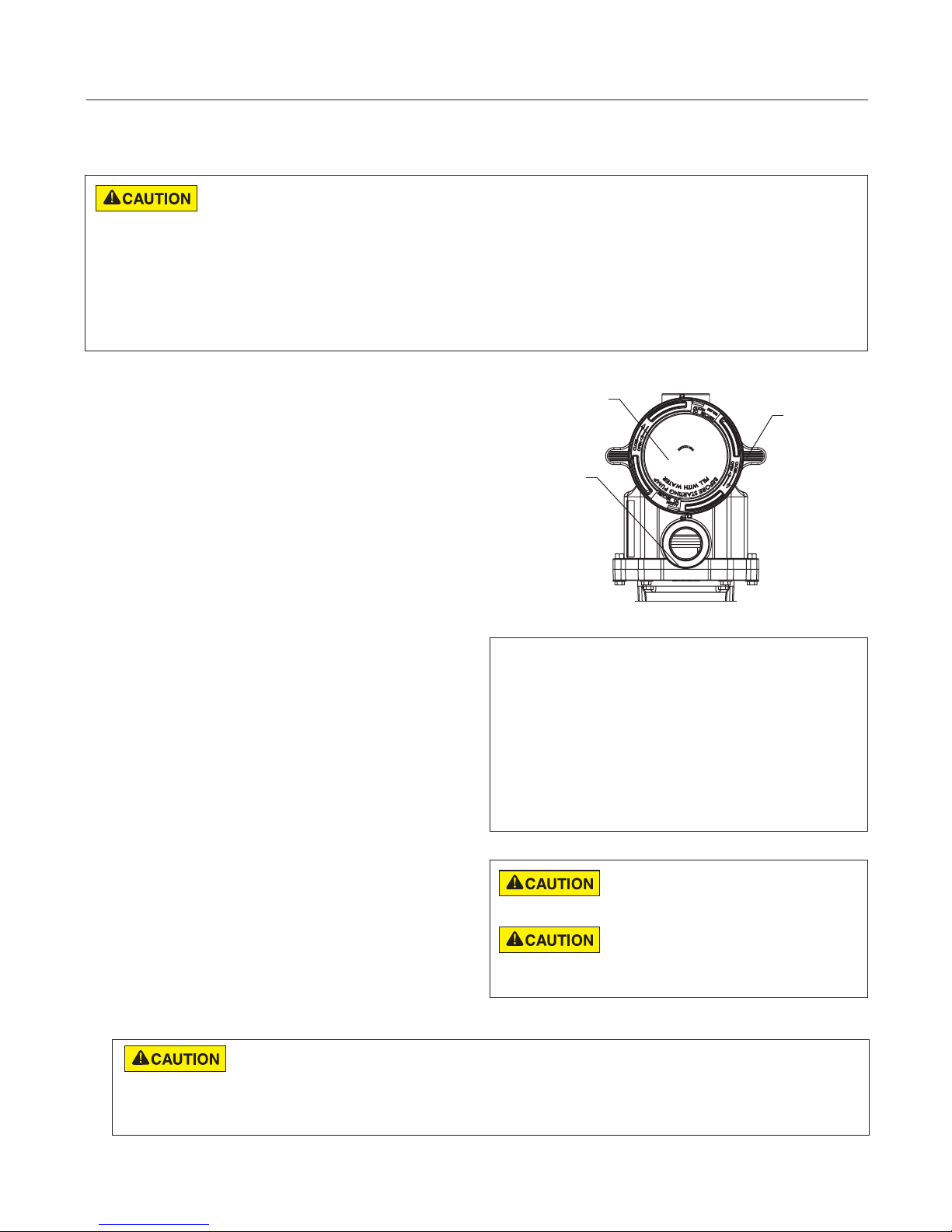
Priming the Pump
Prime the pump before starting the pump for the first
time. Remove the lid and fill the basket with water. The
pump basket must be filled with water before initial
start up or after servicing.
Follow the steps below to prime the pump for start up:
1. Press Start/Stop to stop the pump. Disconnect the
pump main power supply and communication cable.
2. Close all valves in suction and discharge pipes.
Relieve all pressure from the system.
3. Remove the pump lid and locking ring.
4. Fill the pump strainer pot with water.
5. Reassemble the pump lid and locking ring onto the
strainer basket. The pump is now ready to prime.
6. Open all valves in suction and discharge pipes.
7. Open the filter air relief valve and stand clear of the
filter.
8. Connect power to the pump. Be sure green power
light is on.
9. Press Start/Stop to start the pump. The pump will
enter into priming mode (if enabled) and speed
up to the maximum speed set in the pump menu
settings.
10. When water comes out of the filter air relief valve,
close the valve. The system should now be free of
air and recirculating water to and from the pool
11. Do not allow your pump to run longer than 30
minutes time without developing full flow. If the
pump does not prime, check your priming settings
on the control panel or see the “Troubleshooting”
section on pages 25-27.
Priming Features
The default priming setting is ENABLED.
The pump also allows you to set the following from
the operator control panel:
• Priming speed
• Priming range (1-10)
• Priming delay
Set up instructions on page 19.
chemicals may damage the pump and will void the warranty.
heating. The higher speeds can be used for spa jets, water
features, and priming.
Lid
Locking
Ring
Volute
Top View
Do not add chemicals to the system directly
in front of pump suction. Adding undiluted
This is a variable speed pump. Typically
the lower speeds are used for filtration and
5
DO NOT run the pump dry. If the pump is run dry, the mechanical seal will be damaged and the pump will start
leaking. If this occurs, the damaged seal must be replaced. ALWAYS maintain proper water level in your pool
(half way up skimmer opening). If the water level falls below the skimmer opening, the pump will draw air through the skimmer, losing
the prime and causing the pump to run dry, resulting in a damaged seal. Continued operation in this manner could cause a loss of
pressure, resulting in damage to the pump case, impeller and seal and may cause property and personal injury.
INTELLIFLO® VSF Variable Speed and Flow Pump Installation and User’s GuideINTELLIFLO
6
12:15p
750 RPM
T 0.00 150 WATTS
Running Speed 1
SaveBack
Select
Menu
1
5
2
6
8
4
3
7
1 2 3
4
Quick
Clean
Time
Out
12:15p
750 RPM
T 0.00 150 WATTS
Running Speed 1
SaveBack
Select
Menu
1 2 3
4
Quick
Clean
Time
Out
15
Line 1
Line 2
Line 3
Line 4
9
13
12
10
11
14
Save?
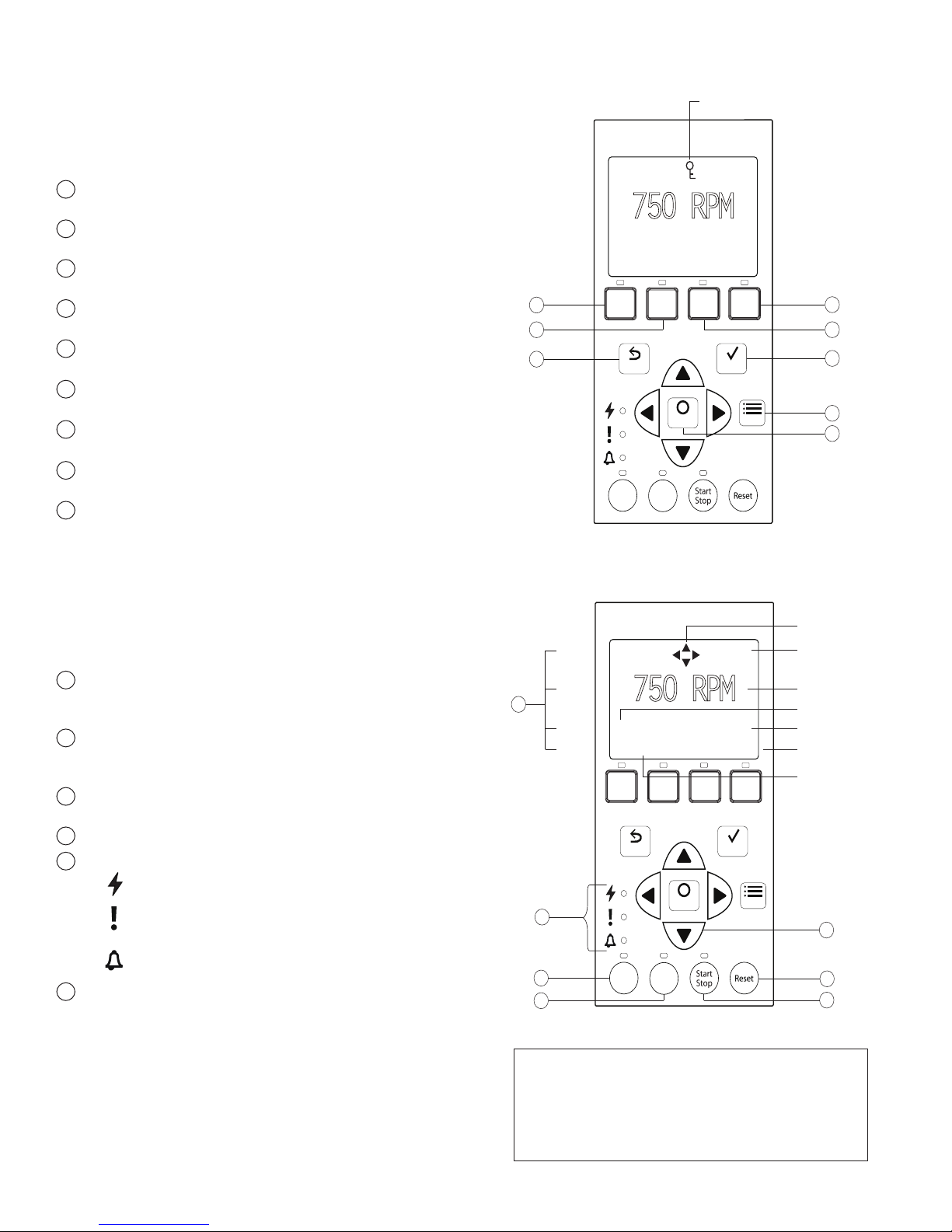
Using the Operator Control Panel
Use the operator control panel to start and stop the IntelliFlo® VSF
Variable Speed and Flow Pump, set, and change programs, and
access pump features and settings.
Controls and LEDs on Keypad
Button 1: Press to select Program 1 (750 RPM). LED on
1
indicates Program 1 is active.
2
Button 2: Press to select Program 2 (1500 RPM). LED on
indicates Program 2 is active.
3
Button 3: Press to select Program 3 (2350 RPM). LED on
indicates Program 3 is active.
4
Button 4: Press to select Program 4 (3110 RPM). LED on
indicates Program 4 is active.
5
Back: Goes one step back in menu; exits without saving
current setting.
6
Save: Saves current menu item setting. When a parameter
has been adjusted the "Save?" icon will be displayed.
7
Menu: Accesses the menu items when and if the pump is
stopped.
8
Select: Press to select the currently displayed option on the
screen.
9
Arrow buttons:
• Up arrow: Move one level up in the menu or increase
a digit when editing a setting.
• Down arrow: Move one level down in the menu or
decrease a digit when editing a setting.
• Left arrow: Move cursor left one digit when editing a
setting.
• Right arrow: Move cursor right one digit when editing
a setting.
10
Quick Clean: Pump increases to a higher RPM (for
vacuuming, cleaning, adding chemicals, etc.). LED light is
on when active.
11
Time Out: Allow the pump to remain in a stopped state for
a set period of time before resuming normal operation. LED
is on when active.
12
Start/Stop button: To start or stop the pump. When LED is
on, the pump is running or in a mode to start automatically.
13
Reset button: Reset alarm or alert.
14
LEDs:
15
Control Panel LCD Screen:
• Line 1: Key icon indicates password protection mode is
On: Green light when pump is powered on.
Warning: On if warning condition is present. See
“Alerts and Warnings” on page 25.
Alarm: Red LED on if alarm condition occurs. See
“Alerts and Warnings” on page 25.
active. If password protect is not enabled, no key icon is
displayed. Also shows current time of day. Active cursors
display when arrow key input is available.
• Line 2: Displays current pump speed/flow (RPM/GPM).
• Line 3: Countdown time and watts
• Line 4: Current pump status and current feature. "Save?"
will display on this line when a parameter adjustment
can be saved.
INTELLIFLO® VSF Variable Speed and Flow Pump Installation and User’s Guide
Key Lockout Icon
Control Panel #1-8
Active Cursors
Current Time
Current Speed/Flow
Countdown Time
Current Power Usage
"Save?" Icon
Current Running
Feature
Control Panel #9-15
Note: Always close the keypad cover after using
the keypad.
Note: Using screwdrivers or pens to program the
pump will damage the keypad overlay. Use your
fingers only when programming the pump.
7
LED lit
1 2 3
4
Manual
Set Speed
Set Duration
Set Speed
Disabled
Set Stop Time
Set Speed
Stopping and Starting the Pump
Starting the Pump
1. Be sure the pump is powered on and the green
power LED is on.
2. Select one of the program buttons, then press the
Start/Stop button (LED on) to start the pump. The
pump will go into priming mode if priming feature
is enabled.
Stopping the Pump
1. Press Start/Stop to stop the pump.
When servicing equipment (filters, heaters, chlorinators
etc.), disconnect the communication cable, and switch
OFF circuit breaker to remove power from the pump.
Note: The pump can automatically restart if the communication cable is connected.
Adjusting and Saving a Pump Speed/Flow
1. While the pump is running, press the Up or Down
arrow to adjust to desired speed or flow setting.
2. Press and hold down a Program button (1-4) for
three (3) seconds to save speed/flow to the button
or press Save to save the speed/flow.
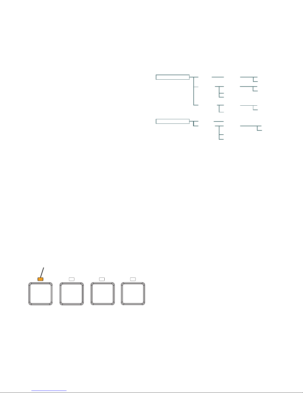
Operating the Pump at Preset Speeds
The pump is programmed with four default speeds of 750,
1500, 2350 and 3110 RPM. Program buttons 1-4 are for
each of the preset speeds as shown below.
1. Be sure the pump is powered on and the green
power LED is on.
2. Press the Program button (1- 4) corresponding to
the desired preset speed and release quickly. The
LED above the button will turn on.
3. Press Start/Stop. The pump will quickly change to
the selected preset speed.
Pump Operating Modes
The IntelliFlo® VSF Variable Speed and Flow Pump can
be programmed in three different modes:
Programs 1-4 can be programmed in all three modes.
Programs 5-8 can only be programmed in Schedule
mode since there are no buttons on the control panel
for Programs 5-8. The default setting for Programs 5-8
is “Disabled”.
Program 1-4
Schedule
Egg Timer
Program 5-8
Schedule
Program Menu Tree Options
Manual
Assigns a speed or flow to one of the four Program
buttons on the control panel. This mode can only be
used for programs 1-4. Programs 1 and 2 are Manual
by default.
To operate in Manual mode, press one of the four
program buttons and then press the Start/Stop button.
The pump will run the assigned speed or flow assigned
to that program button.
Egg Timer
Programs 1-4 can be programmed to run at a certain
speed or flow and for a duration of time once a program
button is pressed.
Programs 3 and 4 are Egg Timers by default. If you
desire a different method of operation, programs 3 and
4 can be changed to Manual mode in the control menu.
To operate in Egg Timer mode, press a program button
and then press Start/Stop. The pump will run that
setting for the set amount of time and then turn off.
Set Type
Set Type
Set Start Time
Set Stop Time
Set Type
Default: Disabled
Set Type
Set Start Time
Set Flow
Set Flow
Set Speed
Set Flow
Set Flow
Set Flow
Set Flow
Set Flow
Set Flow
Schedule
Programs 1-8 start and stop at a specific time during a 24
hour period. Speeds or flows programmed in Schedule
mode will override any manually selected speed or flow
once the next Schedule command commences.
Program Types
This pump can run saved programs at either constant
speeds or constant flow rates. This gives the user the
ability to precisely assign the output from the pump
so that no energy is wasted and the job is completed
accurately.
INTELLIFLO® VSF Variable Speed and Flow Pump Installation and User’s GuideINTELLIFLO
 Loading...