

OWNER’S MANUAL
Self-Priming Centrifugal Pump
For further operating, installation,
293 WRIGHT STREET, DELAVAN, WI 53115 WWW.STA-RITE.COM
PH: 888-782-7483
© 2014 Pentair Ltd. All Rights Reserved. S536 (07/07/14)
“DS3” Series
3621 0714 ASB
Installation/Operation/Parts
or maintenance assistance:
Call 888-782-7483
Safety 2
READ AND FOLLOW
SAFETY INSTRUCTIONS!
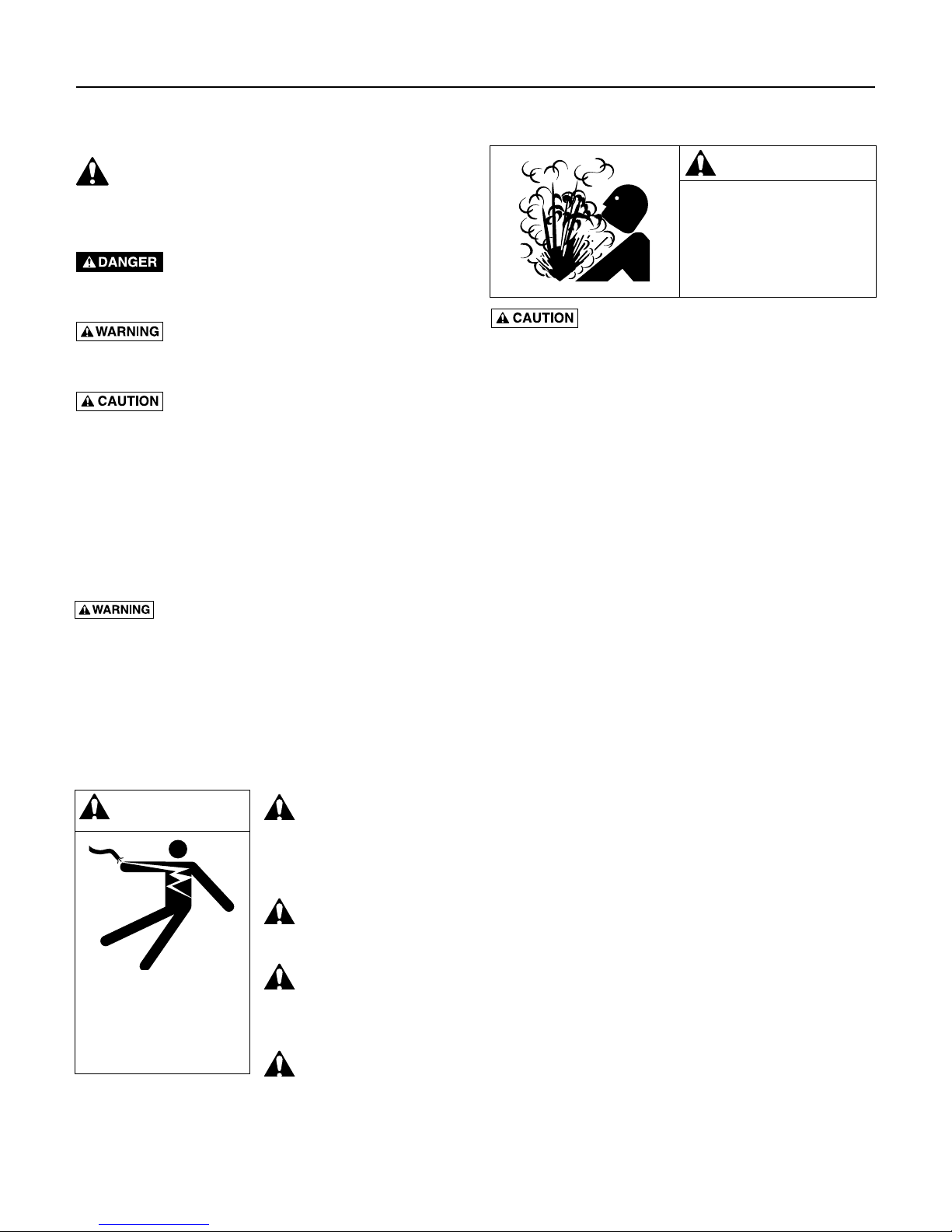
This is the safety alert symbol. When you see this
symbol on your pump or in this manual, look for one of
the following signal words and be alert to the potential
for personal injury.
warns about hazards that will cause serious
personal injury, death or major property damage if
ignored.
warns about hazards that can cause serious
personal injury, death or major property damage if
ignored.
warns about hazards that will or can cause
minor personal injury or property damage if ignored.
The label NOTICE indicates special instructions which
are important but not related to hazards.
Carefully read and follow all safety instructions in this
manual and on pump.
Keep safety labels in good condition.
Replace missing or damaged safety labels.
California Proposition 65 Warning
This product and related accessories contain
chemicals known to the State of California to cause
cancer, birth defects or other reproductive harm.
GENERAL SAFETY
WARNING
Hazardous pressure!
Install pressure relief
valve in discharge pipe.
Release all pressure on
system before working on
any component.
Do not touch an operating motor. Modern
motors can operate at high temperatures. To avoid burns
when servicing pump, allow it to cool for 20 minutes
after shut-down before handling.
Pump is designed as a lawn sprinkler only. To avoid heat
built-up, over pressure hazard and possible injury, do not
use in a pressure tank (domestic water) system. Do not use
as a booster pump; pressurized suction may cause pump
body to explode.
Do not allow pump or piping system to freeze. Freezing
can damage pump and pipe, may lead to injury from
equipment failure and will void warranty.
Pump water only with this pump.
Periodically inspect pump and system components.
Wear safety glasses at all times when working on pumps.
Keep work area clean, uncluttered and properly lighted;
store properly all unused tools and equipment.
Keep visitors at a safe distance from the work areas.
Make workshops childproof; use padlocks and master
switches; remove starter keys.
ELECTRICAL SAFETY
Wire motor for
WARNING
Hazardous voltage.
Can shock, burn, or
cause death.
Ground pump before
connecting to power
supply.
correct voltage.
See “Electri cal” section of
this manual and motor
nameplate.
Ground motor before
connecting to power
supply.
Meet National
Electri cal Code,
Canadian Elec tri cal Code, and
local codes for all wiring.
Follow wiring
instructions in this
manual when connecting
motor to power lines.

Table of Contents 3
Thank you for purchasing a top quality, factory tested pump.
Page
Safety ...................................................................................................................2
Warranty..............................................................................................................3
Installation ........................................................................................................4-5
Electrical ..............................................................................................................6
Operation ............................................................................................................7
Maintenance ...................................................................................................8-10
Troubleshooting ................................................................................................. 11
Repair Parts ......................................................................................................12
Limited Warranty
STA-RITE warrants to the original consumer purchaser (“Purchaser” or “You”) of the products listed below, that they will be free
from defects in material and workmanship for the Warranty Period shown below.
Product Warranty Period
Water Systems Products — jet pumps, small centrifugal pumps,
submersible pumps and related accessories
Pro-Source™ Composite Tanks 5 years from date of original installation
Pro-Source™ Steel Pressure Tanks 5 years from date of original installation
Pro-Source™ Epoxy-Lined Tanks 3 years from date of original installation
Sump/Sewage/Effluent Products
Our warranty will not apply to any product that, in our sole judgement, has been subject to negligence, misapplication,
improper installation, or improper maintenance. Without limiting the foregoing, operating a three phase motor with single phase
power through a phase converter will void the warranty. Note also that three phase motors must be protected by three-leg,
ambient compensated, extra-quick trip overload relays of the recommended size or the warranty is void.
Your only remedy, and STA-RITE’s only duty, is that STA-RITE repair or replace defective products (at STA-RITE’s choice). You
must pay all labor and shipping charges associated with this warranty and must request warranty service through the installing
dealer as soon as a problem is discovered. No request for service will be accepted if received after the Warranty Period has
expired. This warranty is not transferable.
STA-RITE SHALL NOT BE LIABLE FOR ANY CONSEQUENTIAL, INCIDENTAL, OR CONTINGENT DAMAGES WHATSOEVER.
THE FOREGOING WARRANTIES ARE EXCLUSIVE AND IN LIEU OF ALL OTHER EXPRESS AND IMPLIED WARRANTIES,
INCLUDING BUT NOT LIMITED TO THE IMPLIED WARRANTIES OF MERCHANTABILITY AND FITNESS FOR A PARTICULAR
PURPOSE. THE FOREGOING WARRANTIES SHALL NOT EXTEND BEYOND THE DURATION EXPRESSLY PROVIDED HEREIN.
Some states do not allow the exclusion or limitation of incidental or consequential damages or limitations on the duration of an
implied warranty, so the above limitations or exclusions may not apply to You. This warranty gives You specific legal rights and
You may also have other rights which vary from state to state.
This Limited Warranty is effective June 1, 2011 and replaces all undated warranties and warranties dated before June 1, 2011.
whichever occurs first:
12 months from date of original installation,
or 18 months from date of manufacture
12 months from date of original installation, or
18 months from date of manufacture
293 Wright Street • Delavan, WI U.S.A. 53115
Phone: 1-888-782-7483 • Fax: 1-800-426-9446 • Web Site: sta-rite.com
STA-RITE INDUSTRIES
Installation 4
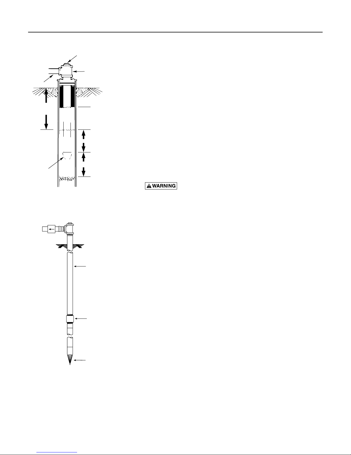
Priming plug
Priming tee
Suction
pipe
20' (6 m) max.
Foot
Valve
Standing water
level (pump off)
Drawdown water
level (pump on)
10-20' (3-6 m)
At least 5 feet (1.5 m)
828 0993
Figure 1: Cased/Dug Well Installation
BEFORE YOU INSTALL YOUR PUMP
NOTICE: Well must not be more than 20’ depth to water.
1. Long runs and many fittings increase friction and reduce flow. Locate
pump as close to well as possible: use as few elbows and fittings as
possible.
2. Be sure well is clear of sand. Sand will plug the pump and void the
warranty.
3. Protect pump and all piping from freezing. Freezing will split pipe,
damage pump and void the warranty. Check locally for frost protection
requirements (usually pipe must be 12” below frost line and pump must
be insulated).
4. Be sure all pipes and foot valve are clean and in good shape.
5. No air pockets in suction pipe.
6. No leaks in suction pipe. Use PTFE pipe thread sealant tape to seal pipe
joints.
7. Unions installed near pump and well will aid in servicing. Leave room
use wrenches.
8. Pump body may explode if used as a booster pump.
DO NOT use in a booster appli cation.
WELL PIPE INSTALLATION
NOTICE: Use the installation method below which matches your well type.
Check valve
Steel drive pipe
Drive coupling
Driven point
Figure 2: Driven Point Installation
CASED WELL INSTALLATION
1. Inspect foot valve to be sure it works freely. Inspect strainer to be sure it
is clean.
2. Connect foot valve and strainer to the first length of suction pipe and
lower pipe into well. Add sections of pipe as needed, using PTFE pipe
thread sealant tape on male threads. Be sure that all suction pipe is
leakproof or pump will lose prime and fail to pump. Install foot valve
10 to 20 feet below the lowest level to which water will drop while
pump is operating (pumping water level). Your well driller can furnish
this in formation.
3. To prevent sand and sediment from entering the pumping system, the
foot valve/strainer should be at least 5 feet above the bottom of the
well.
4. When the proper depth is reached, install a sanitary well seal over the
pipe and in the well casing. Tighten the bolts to seal the casing.
5. When using a foot valve, a priming tee and plug as shown in Figure 1
are recommended.
DUG WELL INSTALLATION
Same as cased well installation.
DRIVEN POINT INSTALLATION
1. Connect the suction pipe to the drive point as illustrated in Figure 2.
Keep horizontal pipe run as short as possible. Use PTFE pip thread
sealant tape on male pipe threads. Multiple well points may be
necessary to provide sufficient water to pump.
2. Install a check valve in horizontal pipe. Flow arrow on check valve
must point toward pump.
 Loading...