

Pentair Sta-Rite DMC Series, Sta-Rite DMC-2-100, Sta-Rite DMC-2-150, Sta-Rite DMC-2-200, DMC-2-200-3 Installation And Operation Manual

Centrifugal Pumps
INSTALLATION AND
OPERATION MANUAL
DMC Series Two - Stage
Horsepower Range: 1- 2 H.P.
60 Cycle
Single Phase Installations
Owner’s Record
Pump Model: _________________________________________________
Pump Serial No.: ______________________________________________
Pump Date Code: ______________________________________________
Motor H.P. _____________ Voltage ____________ Phase ___________
Date of Installation: ____________________________________________
Owner: ______________________________________________________
Installer: _____________________________________________________
Installer Phone Number: _________________________________________
Sta-Rite
293 Wright St., Delavan, WI 53115
PH: 888-782-7483 Orders Fax: 800-426-9446
WWW.STA-RITE.COM
© 2017 S690 (02/27/17)

SAFETY
READ AND FOLLOW
SAFETY INSTRUCTIONS!
This is the safety alert symbol. When you see
this symbol on your pump or in this manual, look for
one of the following signal words and be alert to the
potential for personal injury:
warns about hazards that will cause seri-
ous personal injury, death or major property damage if
ignored.
warns about hazards that can cause seri-
ous personal injury, death or major property damage if
ignored.
warns about hazards that will or can
cause minor personal injury or property damage if
ignored.
The label NOTICE indicates special instructions which
are important but not related to hazards.
Carefully read and follow all safety instructions in
this manual and on pump.
Keep safety labels in good condition.
Replace missing or damaged safety labels.
Make workshops childproof; use padlocks and master
switches; remove starter keys.
California Proposition 65 Warning
This product and related accessories
contain chemicals known to the State of California to
cause cancer, birth defects or other reproductive harm.
ELECTRICAL SAFETY
Capacitor voltage may be hazardous.
To discharge motor capacitor, hold insulated handle
screwdriver BY THE HANDLE and short capacitor ter-
minals together. Do not touch metal screwdriver blade
or capacitor terminals. If in doubt, consult a qualified
electrician.
GENERAL SAFETY
Do not touch an operating motor.
Modern motors can operate at high temperatures. To
avoid burns when servicing pump, allow it to cool for 20
minutes after shut-down before handling.
Do not allow pump or any system component to freeze.
To do so will void warranty.
Pump water only with this pump.
Periodically inspect pump and system components.
Wear safety glasses at all times when working on
pumps.
Keep work area clean, uncluttered and properly lighted;
store properly all unused tools and equipment.
Keep visitors at a safe distance from the work areas.
Never run pump above recommended pressure shown
on the performance chart or with discharge valve
closed.
WARNING
WARNING
Hazardous voltage.
Can shock, burn, or
cause death.
Ground pump before
connecting to power
supply. Disconnect power
before working on pump,
motor or tank.
Wire motor for correct
voltage. See “Electri cal”
section of this manual and
motor nameplate.
Ground motor before
connecting to power
supply.
Meet National Electrical Code, Canadian Elec trical Code, and local codes
for all wiring.
Follow wiring instructions in this manual when
connecting motor to
power lines.
Hazardous pressure!
Do not run pump against
closed discharge.
Release all pressure on
system before working on
any component.
2

WARRANTY
Limited Warranty
STA-RITE warrants to the original consumer purchaser (“Purchaser” or “You”) of the products listed below, that they will be free
from defects in material and workmanship for the Warranty Period shown below.
Product Warranty Period
Water Systems Products — jet pumps, small centrifugal pumps,
submersible pumps and related accessories
Pro-Source™ Composite Tanks 5 years from date of original installation
Pro-Source™ Steel Pressure Tanks 5 years from date of original installation
Pro-Source™ Epoxy-Lined Tanks 3 years from date of original installation
Sump/Sewage/Effluent Products
Our warranty will not apply to any product that, in our sole judgement, has been subject to negligence, misapplication,
improper installation, or improper maintenance. Without limiting the foregoing, operating a three phase motor with single phase
power through a phase converter will void the warranty. Note also that three phase motors must be protected by three-leg,
ambient compensated, extra-quick trip overload relays of the recommended size or the warranty is void.
Your only remedy, and STA-RITE’s only duty, is that STA-RITE repair or replace defective products (at STA-RITE’s choice). You
must pay all labor and shipping charges associated with this warranty and must request warranty service through the installing
dealer as soon as a problem is discovered. No request for service will be accepted if received after the Warranty Period has
expired. This warranty is not transferable.
STA-RITE SHALL NOT BE LIABLE FOR ANY CONSEQUENTIAL, INCIDENTAL, OR CONTINGENT DAMAGES WHATSOEVER.
THE FOREGOING WARRANTIES ARE EXCLUSIVE AND IN LIEU OF ALL OTHER EXPRESS AND IMPLIED WARRANTIES,
INCLUDING BUT NOT LIMITED TO THE IMPLIED WARRANTIES OF MERCHANTABILITY AND FITNESS FOR A PARTICULAR
PURPOSE. THE FOREGOING WARRANTIES SHALL NOT EXTEND BEYOND THE DURATION EXPRESSLY PROVIDED HEREIN.
Some states do not allow the exclusion or limitation of incidental or consequential damages or limitations on the duration of an
implied warranty, so the above limitations or exclusions may not apply to You. This warranty gives You specific legal rights and
You may also have other rights which vary from state to state.
This Limited Warranty is effective June 1, 2011 and replaces all undated warranties and warranties dated before June 1, 2011.
whichever occurs first:
12 months from date of original installation,
or 18 months from date of manufacture
12 months from date of original installation, or
18 months from date of manufacture
STA-RITE INDUSTRIES
293 Wright Street • Delavan, WI U.S.A. 53115
Phone: 1-888-782-7483 • Fax: 1-800-426-9446 • Web Site: sta-rite.com
3
INSTALLATION
BEFORE YOU INSTALL YOUR PUMP
NOTICE: Well must not be more than 20’ (6.1m) depth
to water.
Step 1. Long runs and many fittings increase friction
and reduce flow. Locate pump as close to well
as possible; use as few elbows and fittings as
possible. Be sure suction line is straight and
angles toward pump.
Step 2. Be sure well and pipe are clear of sand, dirt and
scale. Foreign matter will plug pump and void
warranty. Use new pipe for best results.
Step 3. Protect pump and all piping from freezing.
Freezing will split pipe, damage pump and
void warranty. Check locally for frost protection requirements (usually pipe must be 12”
(30.5cm) below frost line and pump must be
insulated).
Step 4. Be sure all pipes and foot valve are clean and in
good shape.
Step 5. No air pockets in suction pipe.
Step 6. No leaks in suction pipe. Use Teflon tape or
Plasto-Joint Stik to seal pipe joints.
Step 7. Unions installed near pump and well will aid in
servicing. Leave room to use wrenches.
CASED WELL/DUG WELL INSTALLATION
Step 1. Inspect foot valve to be sure it works free-
ly. Inspect strainer to be sure it is clean and
secure.
Step 2. Connect foot valve and strainer to first length of
suction pipe and lower pipe into well. Add sections of pipe as needed, using Teflon tape on
male threads (use 1-1/2” pipe for suction pipe).
Be sure all suction pipe is leakproof or pump will
lose prime and fail to pump. Install foot valve 10
to 20 ft. (3 to 6 m) below lowest level to which
water will drop while pump is operating (pumping water level). Your well driller can furnish this
information.
Step 3. To prevent sand and sediment from entering
pumping system, foot valve/strainer should be
at least 5 ft. (1.5 m) above bottom of well.
Step 4. When proper depth is reached, install sanitary
well seal over pipe and in well casing. Tighten
bolts to seal casing.
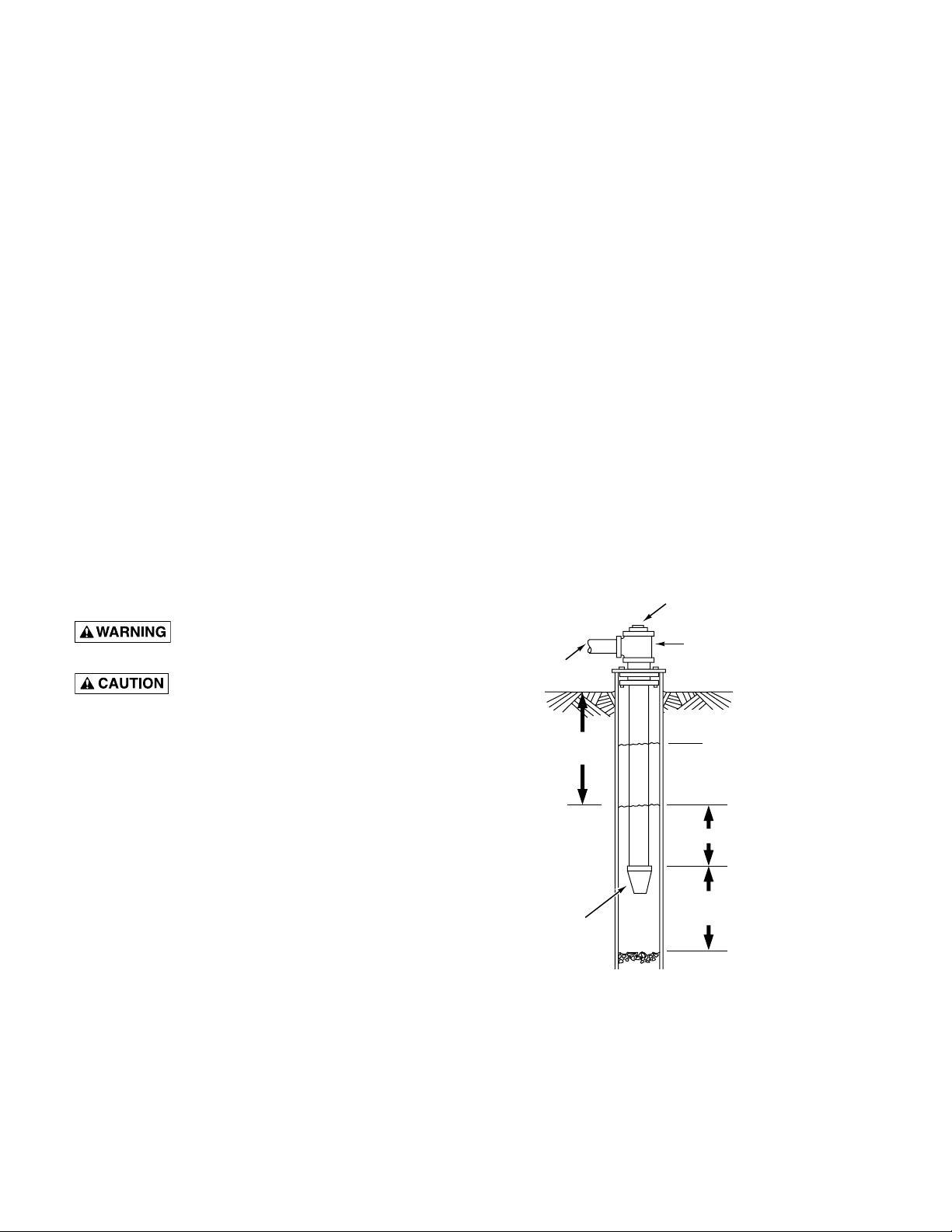
Step 5. When using foot valve, a priming tee and plug
are recommended. (Fig. 1).
Priming plug
Pump body may explode if used as
booster pump. DO NOT use in booster application.
Motor normally operates at high temperature and will be too hot to touch. It is protected from
heat damage during operation by an automatic internal
cutoff switch. Before handling pump or motor, stop
motor and allow it to cool for 20 minutes.
WELL PIPE INSTALLATION
NOTICE: Use installation method below which matches
your well type.
Priming tee
Suction
pipe
Standing water
20' (6 m)
max.
Foot
Valve
level (pump off)
Drawdown water
level (pump on)
10-20' (3-6 m)
At least 5 feet
(1.5 m)
Figure 1: Cased/Dug Well Installation
4
INSTALLATION
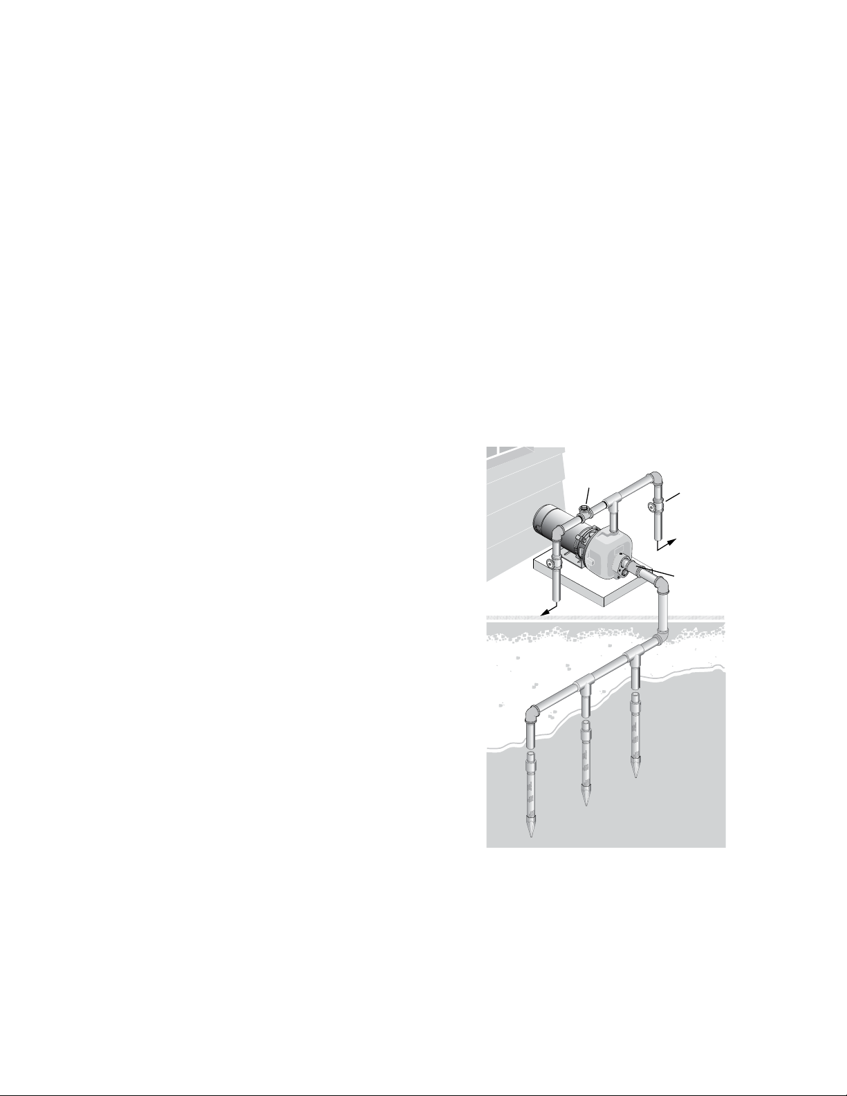
DRIVEN POINT INSTALLATION
Step 1. Connect suction pipe to drive point (Fig. 2).
Keep horizontal pipe run as short as possible.
Use Teflon tape on male pipe threads. Multiple
well points may be necessary to provide sufficient water to pump.
Step 2. Install check valve in horizontal pipe. Flow
arrow on check valve must point toward pump.
HORIZONTAL PIPING FROM WELL TO
PUMP
Step 1. Pump performance will be decreased if less that
1-1/2” pipe is used as suction pipe.
Step 2. To aid priming on well point installations, install
line check valve. Be sure check valve flow
arrow points toward pump.
DISCHARGE PIPE SIZES
Discharge pipe size should be increased to reduce
pressure losses caused by friction on long pipe runs.
Pipe sizing is based on GPM, type of pipe, and length
of pipe.
LAWN SPRINKLING APPLICATION
This pump is designed for lawn sprinkling. Delivers
plenty of water at full sprinkler pressure. Pumps from
pond, cistern or well points.
Pump discharge can be divided to supply 4 or more
sprinkler systems.
Do not use in booster pump applications.
Step 1. Bolt pump to solid, level foundation.
Step 2. Support all piping connected to pump.
Step 3. Wrap 1-1/2 to 2 layers of Teflon tape clockwise
(as you face end of pipe) on all male threads
being attached to pump.
Step 4. Tighten joints hand tight plus 1-1/2 turns. Do
not overtighten.
Step 5. Replace prime plug with pressure gauge. This
will aid in sizing zones, troubleshooting, and following pump performance chart.
NOTICE: Install pump as close to well head as possible. Long piping runs and many fittings create friction
and reduce flow.
NOTICE: For long horizontal pipe runs, install a priming
tee between check valve and well head (Fig. 1). For
driven point installations, install check valve. Be sure
that check valve flow arrow points toward pump.
To sprinkler
heads
Priming
tee
Gate
valve
To sprinkler
heads
Check
valve
PUMP/PIPING INSTALLATION
If turning pump on and off by pressure, a pressure
switch and tank are required. For proper installation and
operation instructions call Customer Service.
Use rigid pipe. Do not use hose or plastic tubing. See
“Well Pipe Installation” for more information.
NOTICE: Use only Teflon tape or Teflon based joint
compounds for making all threaded connections to the
pump itself. Do not use pipe joint compounds on
plastic pumps: they can react with the plastic in pump
components. Make sure that all pipe joints in the suction
pipe are air tight as well as water tight. If the suction
pipe can suck air, the pump will not be able to pull
water from the well.
Multiple well
points
Figure 2: Driven Point Installation,
Multiple Well Points
5
ELECTRICAL
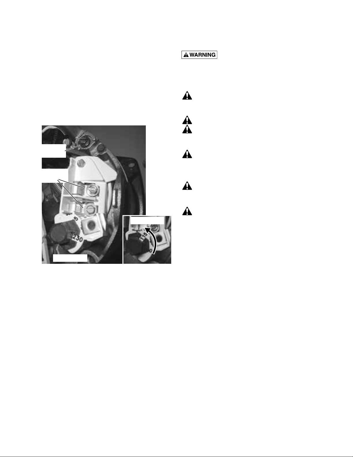
Connection diagram for dual voltage, single-phase
motors. Your dual-voltage motor’s terminal board
(under the motor end cover) will look like Figure 3. If
your power supply is 115 volts, use a flat-bladed screwdriver or a nut driver to change the dial from 230 volts
to
115 volts (see Figure 3). Connect power supply wires
to L1 and L2.
Note: For 3-phase motors, or if motor does not match
these pictures, follow the connection diagram on the
motor nameplate.
Ground Wire
Terminal
Power Supply
Terminals
For 115 Volt
Hazardous voltage. Can shock, burn,
or cause death. Disconnect power to motor before
working on pump or motor. Ground motor before
connecting to power supply.
WIRING
Ground motor before connecting to electrical
power supply. Failure to ground motor can cause
severe or fatal electrical shock hazard.
Do not ground to a gas supply line.
To avoid dangerous or fatal electrical shock,
turn OFF power to motor before working on electrical connections.
Supply voltage must be within ±10% of nameplate voltage. Incorrect voltage can cause fire or
damage motor and voids warranty. If in doubt consult a licensed electrician.
Use wire size specified in Wiring Chart (Page 7).
If possible, connect pump to a separate branch circuit with no other appliances on it.
Wire motor according to diagram on motor
nameplate. If nameplate diagram differs from diagrams above, follow nameplate diagram.
For 230 Volt
Figure 3 – 115/230V Dual Voltage Single Phase Wiring
Diagram
Step 1. Install, ground, wire and maintain this pump in
accordance with electrical code requirements.
Consult your local building inspector for information about codes.
Step 2. Provide a correctly fused disconnect switch for
protection while working on motor. Consult
local or national electrical codes for switch
requirements.
Step 3. Disconnect power before servicing motor or
pump. If the disconnect switch is out of sight of
pump, lock it open and tag it to prevent unexpected power application.
6

ELECTRICAL
Step 4. Ground the pump permanently using a wire of
the same size as that specified in wiring chart,
below. Make ground connection to green
grounding terminal under motor canopy marked
GRD. or .
Step 5. Connect ground wire to a grounded lead in the
service panel or to a metal underground water
pipe or well casing at least 10 feet long. Do not
connect to plastic pipe or insulated fittings.
Step 6. Protect current carrying and grounding conduc-
tors from cuts, grease, heat, oil, and chemicals.
Step 7. Connect current carrying conductors to ter-
minals L1 and L2 under motor canopy. When
IMPORTANT: 115/230 Volt single phase models are
shipped from factory with motor wired for 230 volts. If
power supply is 115 volts, remove motor canopy and
reconnect motor as shown in Figure 3. Do not try to run
motor as received on 115 volt current.
Step 8. Motor has automatic internal thermal overload
protection. If motor has stopped for unknown
reasons, thermal overload may restart it unexpectedly, which could cause injury or property
damage. Disconnect power before servicing
motor.
Step 9. For more assistance on this procedure or the
wiring diagrams, consult a licensed electrician.
replacing motor, check wiring diagram on motor
nameplate against Figure 3. If the motor wiring diagram does not match either diagram in
Figure 3, follow the diagram on the motor.
Recommended Wire and Fuse Sizes
Distance in Feet (M) from Meter to Motor for AWG Wire Sizes
HP Wire Volts #14 AWG #12 AWG #10 AWG #8 AWG #6 AWG #4 AWG #2 AWG #0 AWG
1
230 20 134’ (41) 204 (62) 326 (99) 511 (156) 770 (235) 1183 (361) — —
460 5 1103 (336) — — — — — — —
230 25 105 (32) 160 (49) 255 (78) 400 (122) 602 (183) 926 (282) 1351 (412)
1-1/2
460 7 - 1/2 788 (240) 1249 (381) — — — — — —
2 1 230 30 85 (26) 129 (39) 206 (63) 323 (98) 486 (148) 747 (228) 1090 (332) —
460 10 669 (204) 1060 (323) — — — — — —
115 40 — 51’ (16) 82’ (25) 128’ (39) 182’ (55) 296’ (90) 432’ (132) 592’ (180)
1
230 10 276 (84) 437 (133) 685 (209) 1055 (322) — — — —
3
115 45 — — 64 (20) 100 (30) 151 (46) 232 (271) 338 (103) 463 (141)
1
230 15 197 (60) 312 (95) 489 (149) 753 (230) 1785 (544) — — —
3
230 20 167 (51) 265 (81) 415 (126) 640 (195) 982 (299) 1515 (462) — —
3
Fuse
Rating
(amps)
Pumping Capacity in GPM (LPM) at Indicated Pressure and Depth
Discharge Depth To Water In Feet (Meters)
Pressure
Catalog No. Order No. HP in PSI (kPa) 5’ (1.5) 10’ (3) 15’ (4.6) 20’ (6.1) 25’ (7.6)
30 (207) 36 (136) 35 (132) 33 (125) 31 (117) 28 (106)
DMC-2-100
40 (276) 27 (102) 26 (98) 23 (87) 19 (72) 16 (61)
50 (345) 14 (53) — — — —
30 (207) 43 (163) 42 (159) 41 (155) 40 (151) 39 (148)
DMC-2-150 07053
40 (276) 37 (140) 36 (136) 35 (132) 33 (125) 31 (117)
50 (345) 30 (114) 27 (102) 25 (95) 22 (83) 19 (72)
60 (413) 15 (57) 10 (38) — — —
DMC-2-200
and 40 (276) 44 (167) 43 (163) 42 (159) 40 (151) 39 (148)
DMC-2-200-3 50 (345) 38 (144) 36 (136) 35 (132) 33 (125) 31 (117)
(3-phase) 60 (413) 30 (114) 27 (102) 24 (91) 21 (79) 15 (57)
07052
07054
20 (138) 43 (163) 42 (159) 41 (155) 39 (148) 37 (140)
1
20 (138) 49 (185) 47 (178) 46 (174) 45 (170) 44 (167)
1-1/2
30 (207) 49 (185) 48 (182) 47 (178) 46 (174) 46 (174)
2
7
OPERATION
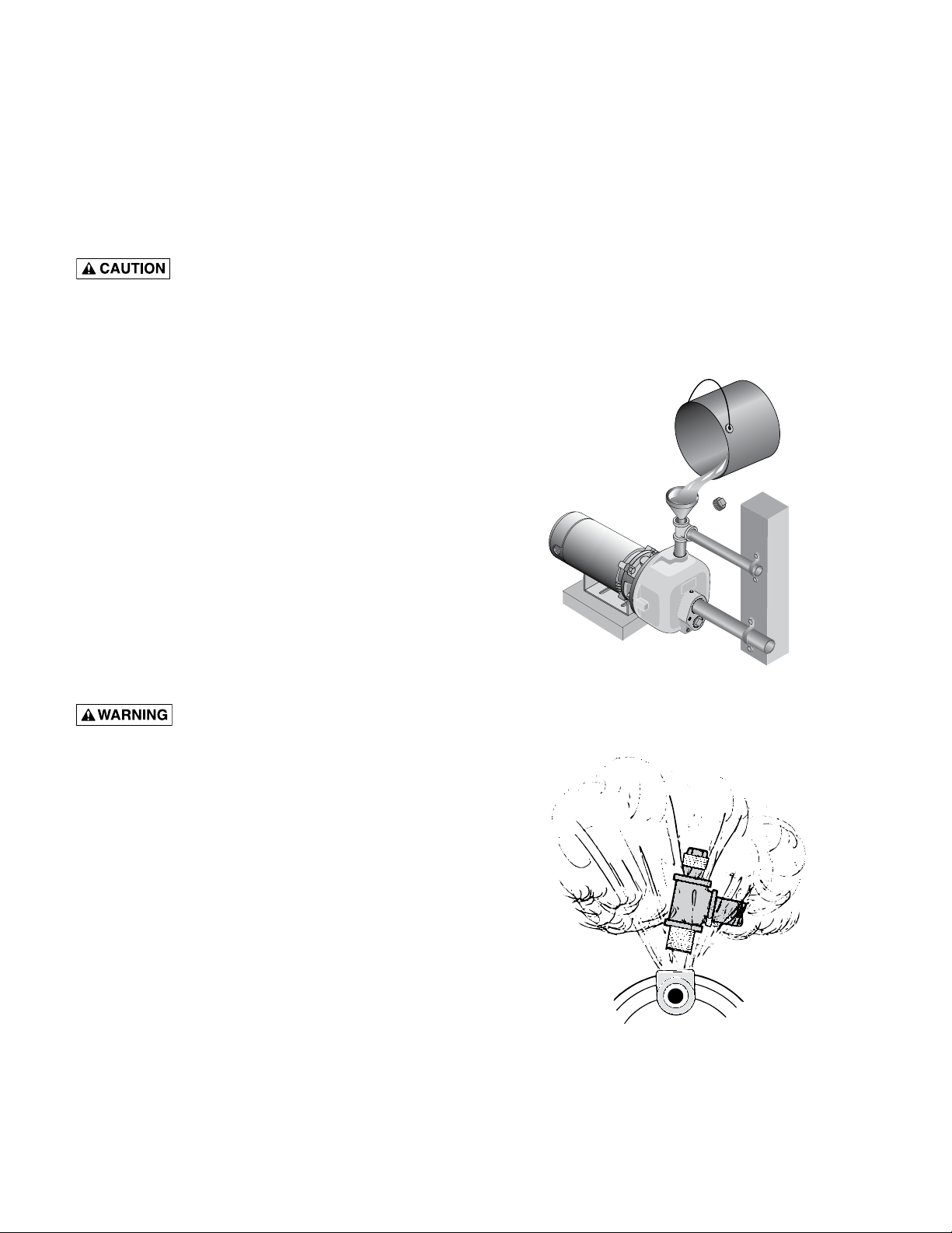
PRIMING THE PUMP
NOTICE: ‘Priming’ refers to pump expelling all air in the
system and beginning to move water from its source
out into system. It does not refer only to pouring water
into pump (although pouring water in is usually the first
step).
NEVER run pump dry. Running pump
without water may cause pump to overheat, damaging seal and possibly causing burns to persons
handling pump. Fill pump with water before starting.
Step 1. Remove priming plug.
Step 2. Make sure suction and discharge valves and
any hoses on discharge side of pump are open.
Step 3. Fill pump and suction pipe with water (Fig. 4).
Step 4. Replace priming plug, using Teflon tape on
thread; tighten plug.
NOTICE: If priming tee and plug have been
provided for long horizontal run, be sure to fill
suction pipe through this tee and replace plug.
(Use Teflon tape on plug.)
Step 5. Start pump; water should be produced in 10
minutes or less, time depends on depth to water
(not more than 20’ (6 m)) and length of horizon-
tal run (10’ (3 m) of horizontal suction pipe = 1’
(30.5 cm) of vertical lift due to friction losses in
pipe). If no water is produced within 10 minutes,
stop pump, release all pressure, remove prim-
ing plug, refill and try again.
Step B. If pump fails to produce water when attempting
to prime, release all pressure, drain pump and
refill with cold water after every attempt.
Step C. When priming, monitor pump body and piping
temperature. Motor will warm up; this is normal.
If pump body or piping begin to feel warm to
touch, shut off pump and allow system to cool.
Release all pressure in system and refill pump
and piping with cold water.
Step D. Make sure discharge pipe and zone size are
not too small for this pumps performance.
Figure 4: Fill Pump Before Starting
NEVER run pump against closed discharge. To do so can boil water inside pump, causing hazardous pressure in unit, risk of explosion
and possibly scalding persons handling pump (Fig.
5). Replace priming plug with pressure gauge to
monitor pressure so that it is not allowed to exceed
maximum pumping pressures according to performance chart.
NOTICE: Open water system faucets before priming
pump for the first time.
Remove priming plug.
Step A. Fully open control valve (turn counterclockwise).
Step B. Fill pump and suction pipe with water.
Step C. Replace priming plug, using Teflon tape on plug
thread; tighten plug.
To prevent explosion, do the following:
Step A. Be sure discharge (valve, pistol grip hose noz-
zle, etc.) is open whenever pump is running.
Figure 5: Do Not Run Pump With
Outlet Shut Off
8

TROUBLESHOOTING
capacitor terminals together. Do not touch metal screwdriver blade or capacitor terminals. If in doubt, consult a qualified electrician.
Capacitor voltage may be hazardous. To discharge capacitor, hold insulated handle screwdriver BY THE HANDLE and short
SYMPTOM POSSIBLE CAUSE(S) CORRECTIVE ACTION
Motor will not run Disconnect switch is off Be sure switch is on.
Fuse is blown or circuit breaker tripped Replace fuse or reset circuit breaker.
Starting switch is defective DISCONNECT POWER; Replace starting switch.
Wires at motor are loose, Refer to instructions on wiring (Page 7). DISCONNECT POWER; check and
disconnected, or wired incorrectly tighten all wiring.
Motor runs hot and Motor is wired incorrectly Refer to instructions on wiring.
overload kicks off or
motor does not run
and only hums
Motor runs but no Pump in new installation did In new installation:
water is delivered* not pick up prime through:
1. Improper priming 1. Re-prime according to instructions.
2. Air leaks 2. Check all connections on suction line, with soapy water or
shaving cream.
* (Note: Stop pump;
3. Leaking foot valve or check valve 3. Replace foot valve or check valve.
then check prime
4. Pipe size too small 4. Re-pipe using size of suction and discharge ports on pump.
before looking
Pump has lost prime through: In installation already in use:
for
other causes.
1. Air leaks 1. Check all connections on suction line and shaft seal with soapy water.
Unscrew
2. Water level below suction pipe inlet 2. Lower suction line into water and re-prime. If receding water level
plug and see if water
in well exceeds 25’ (7.6M), a deep well pump is needed.
is in priming hole).
Impeller is plugged Clean impeller.
Check valve or foot valve is stuck shut Replace check valve or foot valve.
Pipes are frozen Thaw pipes. Bury pipes below frost line. Heat pit or pump house.
Foot valve and/or strainer are Raise foot valve and/or strainer above bottom of water source.
buried in sand or mud Clean foot valve and strainer.
*Pump does not Water level in well is lower than A deep well jet will be needed if your well is more than 25’ (7.6M)
deliver water to full estimated depth to water.
capacity
limed, causing excess friction
Piping is too small in size Re-pipe using size of suction and discharge ports on pump.
Pump not being supplied with Add additional well points.
enough water
priming
Steel piping (if used) is corroded or Replace with plastic pipe where possible, otherwise with new steel pipe.
Voltage is too low Check voltage being supplied to motor. Install heavier wiring if wire size is
too small (See Electrical / Wiring Chart).
9
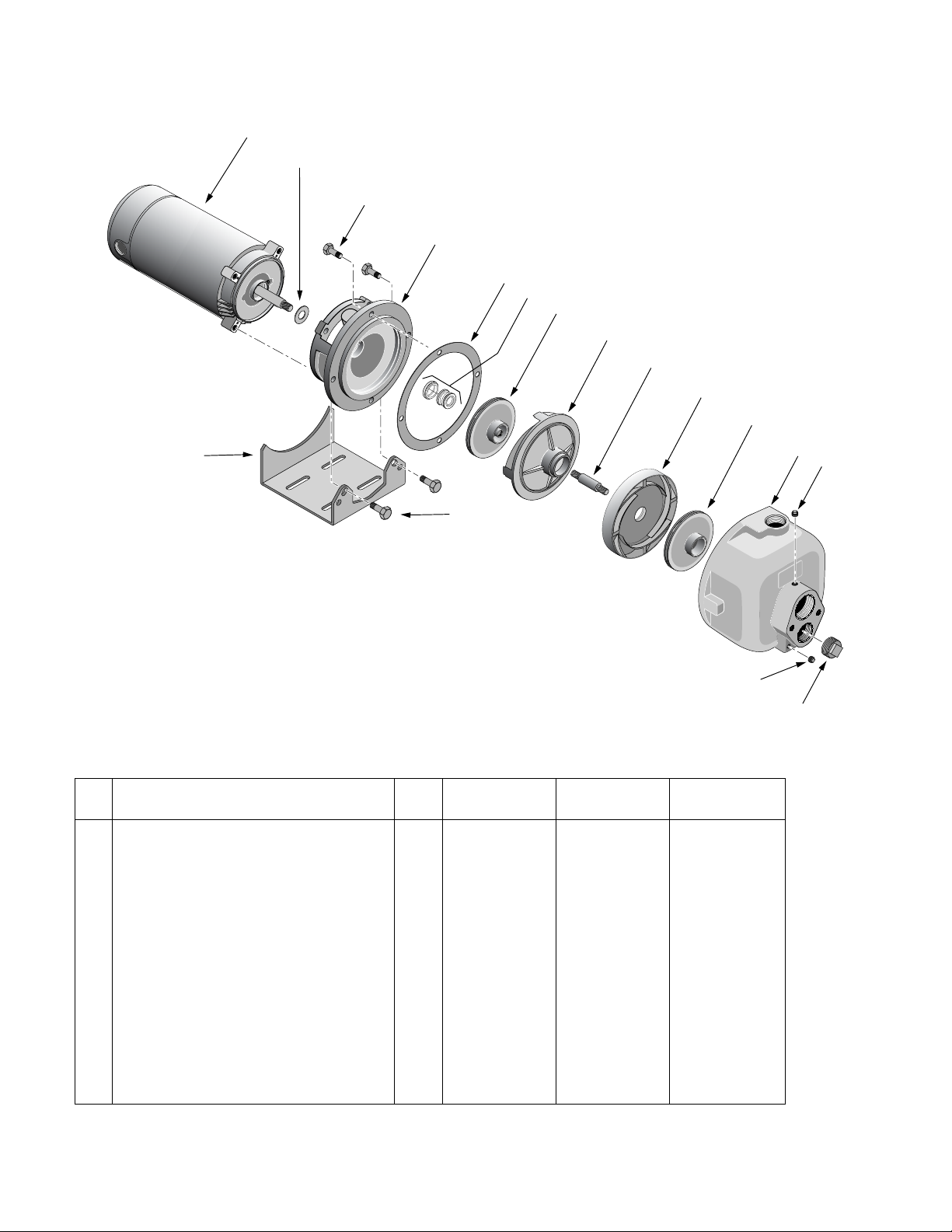
REPAIR PARTS
1
14
2
3
4
5
6
7
8
9
10
11
15
3
13
4286 1202
Repair Parts
Key DMC-2-100 DMC-2-150 DMC-2-200
No. Description Qty. 1 HP 1-1/2 HP 2 HP
1 Motor 1 77026 77145 77024*
2 Slinger 1 17351-0009 17351-0009 17359-0009
3 3/8-16x1” Capscrew 8 † † †
4 Seal Plate/Bracket 1 27433 27433 27433
5 Gasket 1 26360 26360 26360
6 Shaft Seal 1 17038 17038 17038
7 Rear Impeller 1 31290 31289 31290
8 Rear Diffuser 1 26322 26322 26322
9 Shaft Extension 1 34834 34834 34834
10 Front Diffuser 1 86807 86807 86807
11 Front Impeller 1 27387 27387 27387
12 Pump Body 1 27369 27369 27369
13 1/4” -18 Square Head Pipe Plug 2 † † †
14 1”–11-1/2 Square Head Pipe Plug 1 † † †
15 Motor Base 1 34867 34867 34867*
† Purchase locally.
* 3HP DMC-2-200-3 uses 3-phase motor 76909 and motor base 35004.
12
13
10
 Loading...