

OWNER’S MANUAL
Vertical Jet Pumps
For further operating, installation,
293 WRIGHT STREET, DELAVAN, WI 53115 WWW.STA-RITE.COM
PH: 888-782-7483
© 2013 Pentair Ltd. All Rights Reserved. S724 (REV 01/14/13)
2875 0697ASB
“SSJ” Series
Installation/Operation/Parts
or maintenance assistance:
Call 1-888-782-7483
Safety 2
READ AND FOLLOW
SAFETY INSTRUCTIONS!
This is the safety alert symbol. When you see this
symbol on your pump or in this manual, look for one of
the following signal words and be alert to the potential
for personal injury:
warns about hazards that will cause serious
personal injury, death or major property damage if
ignored.
personal injury, death or major property damage if
ignored.
minor personal injury or property damage if ignored.
The label NOTICE indicates special instructions which
are important but not related to hazards.
Carefully read and follow all safety instructions in this
manual and on pump.
Keep safety labels in good condition.
Replace missing or damaged safety labels.
Make workshops childproof; use padlocks and master
switches; remove keys.
California Proposition 65 Warning
chemicals known to the State of California to cause
cancer, birth defects or other reproductive harm.
warns about hazards that can cause serious
warns about hazards that will or can cause
This product and related accessories contain
ELECTRICAL SAFETY
Capacitor voltage may be hazardous.
To discharge motor capacitor, hold insulated handle
screwdriver BY THE HANDLE and short capacitor
terminals together. Do not touch metal screwdriver
blade or capacitor terminals. If in doubt, consult a
qualified
electrician.
GENERAL SAFETY
Do not touch an operating motor. Modern
motors can operate at high temperatures. To avoid burns
when servicing pump, allow it to cool for 20 minutes
after shut-down before handling.
Do not allow pump or any system component to freeze.
To do so will void warranty.
Pump only water with this pump.
Periodically inspect pump and system components.
Wear safety glasses at all times when working on pumps.
Keep work area clean, uncluttered and properly lighted;
store all unused tools and equipment.
Keep visitors at a safe distance from the work areas.
Pump body may explode if used as a
booster pump unless relief valve capable of passing full
pump flow at 75 psi is installed.
WARNING
Hazardous voltage.
Can shock, burn, or
cause death.
Ground pump before
connecting to power
supply. Disconnect power
before working on pump,
motor or tank.
Wire motor for correct
voltage. See “Electri cal”
section of this manual and
motor nameplate.
Ground motor before
connecting to power supply.
Meet National
Electrical Code, Canadian
Elec tri cal Code, and local
codes for all wiring.
Follow wiring
instructions in this manual
when connecting motor to
power lines.
WARNING
Hazardous pressure!
Install pressure relief
valve in discharge pipe.
Release all pressure on
system before working on
any component.
Table of Contents 3
Thank you for purchasing a top quality, factory tested pump.
Page
General Safety .....................................................................................................2
Warranty..............................................................................................................3
Installation ........................................................................................................4-6
Electrical ...........................................................................................................7,8
Operation .......................................................................................................9,10
Maintenance .................................................................................................10-12
Repair Parts .................................................................................................13,14
Troubleshooting ................................................................................................. 15
Limited Warranty
STA-RITE warrants to the original consumer purchaser (“Purchaser” or “You”) of the products listed below, that they will be free
from defects in material and workmanship for the Warranty Period shown below.
Product Warranty Period
Water Systems Products — jet pumps, small centrifugal pumps,
submersible pumps and related accessories
Pro-Source™ Composite Tanks 5 years from date of original installation
Pro-Source™ Steel Pressure Tanks 5 years from date of original installation
Pro-Source™ Epoxy-Lined Tanks 3 years from date of original installation
Sump/Sewage/Effluent Products
Our warranty will not apply to any product that, in our sole judgement, has been subject to negligence, misapplication,
improper installation, or improper maintenance. Without limiting the foregoing, operating a three phase motor with single phase
power through a phase converter will void the warranty. Note also that three phase motors must be protected by three-leg,
ambient compensated, extra-quick trip overload relays of the recommended size or the warranty is void.
Your only remedy, and STA-RITE’s only duty, is that STA-RITE repair or replace defective products (at STA-RITE’s choice). You
must pay all labor and shipping charges associated with this warranty and must request warranty service through the installing
dealer as soon as a problem is discovered. No request for service will be accepted if received after the Warranty Period has
expired. This warranty is not transferable.
STA-RITE SHALL NOT BE LIABLE FOR ANY CONSEQUENTIAL, INCIDENTAL, OR CONTINGENT DAMAGES WHATSOEVER.
THE FOREGOING WARRANTIES ARE EXCLUSIVE AND IN LIEU OF ALL OTHER EXPRESS AND IMPLIED WARRANTIES,
INCLUDING BUT NOT LIMITED TO THE IMPLIED WARRANTIES OF MERCHANTABILITY AND FITNESS FOR A PARTICULAR
PURPOSE. THE FOREGOING WARRANTIES SHALL NOT EXTEND BEYOND THE DURATION EXPRESSLY PROVIDED HEREIN.
Some states do not allow the exclusion or limitation of incidental or consequential damages or limitations on the duration of an
implied warranty, so the above limitations or exclusions may not apply to You. This warranty gives You specific legal rights and
You may also have other rights which vary from state to state.
This Limited Warranty is effective June 1, 2011 and replaces all undated warranties and warranties dated before June 1, 2011.
whichever occurs first:
12 months from date of original installation,
or 18 months from date of manufacture
12 months from date of original installation, or
18 months from date of manufacture
293 Wright Street • Delavan, WI U.S.A. 53115
Phone: 1-888-782-7483 • Fax: 1-800-426-9446 • Web Site: sta-rite.com
STA-RITE INDUSTRIES
Installation 4
Pump
Gasket
Adapter Flange
Sanitary
Well Seal
1" Drive Pipe
Ejector Assembly
Foot Valve & Strainer
1-1/4" Suction Pipe
Threadless Coupling
B-OVER THE WELL INSTALLATION
STEEL PIPE SHOWN
Pump
Gasket
Adapter Flange
Sanitary
Well Seal
Steel Pipe Nipple
Coupling
1" Plastic Drive Pipe
1-1/4" Plastic Suction Pipe
Special 1-1/4" Plastic Pipe
Adapter. (Supplied with Ejector)
1" Plastic Pipe Adapter
Ejector Assembly
Foot Valve & Strainer
A-OFFSET INSTALLATION
PLASTIC PIPE SHOWN
Threadless
Coupling
BEFORE YOU INSTALL YOUR PUMP
NOTICE: For proper performance, pump MUST be matched to ejector and
to well depth. This pump is designed for wells from 25 ft. to 130 ft. depth
from well head to water.
• Long runs and many fittings increase friction and reduce flow. Locate
pump as close to well as possible: use as few elbows and fittings as
possible.
• Be sure well is clear of sand. Sand will plug the pump and void the
warranty.
• Protect pump and all piping from freezing. Freezing will split pipe,
damage pump and void the warranty. Check locally for frost protection
requirements (usually pipe must be 12” below frost line and pump must
be insulated).
• Be sure all pipes and foot valve are clean and in good condition.
• Remove air pockets in suction pipe.
• Make sure there are no leaks in the suction pipe. Use PTFE pipe thread
sealant tape tape to seal pipe joints.
• Unions installed near pump and well will aid in servicing. Leave room
to use wrenches.
• Plug 1” drive port when installing on shallow well.
IMPORTANT: Your well must be able to replenish the water level faster
than the flow out through pump!
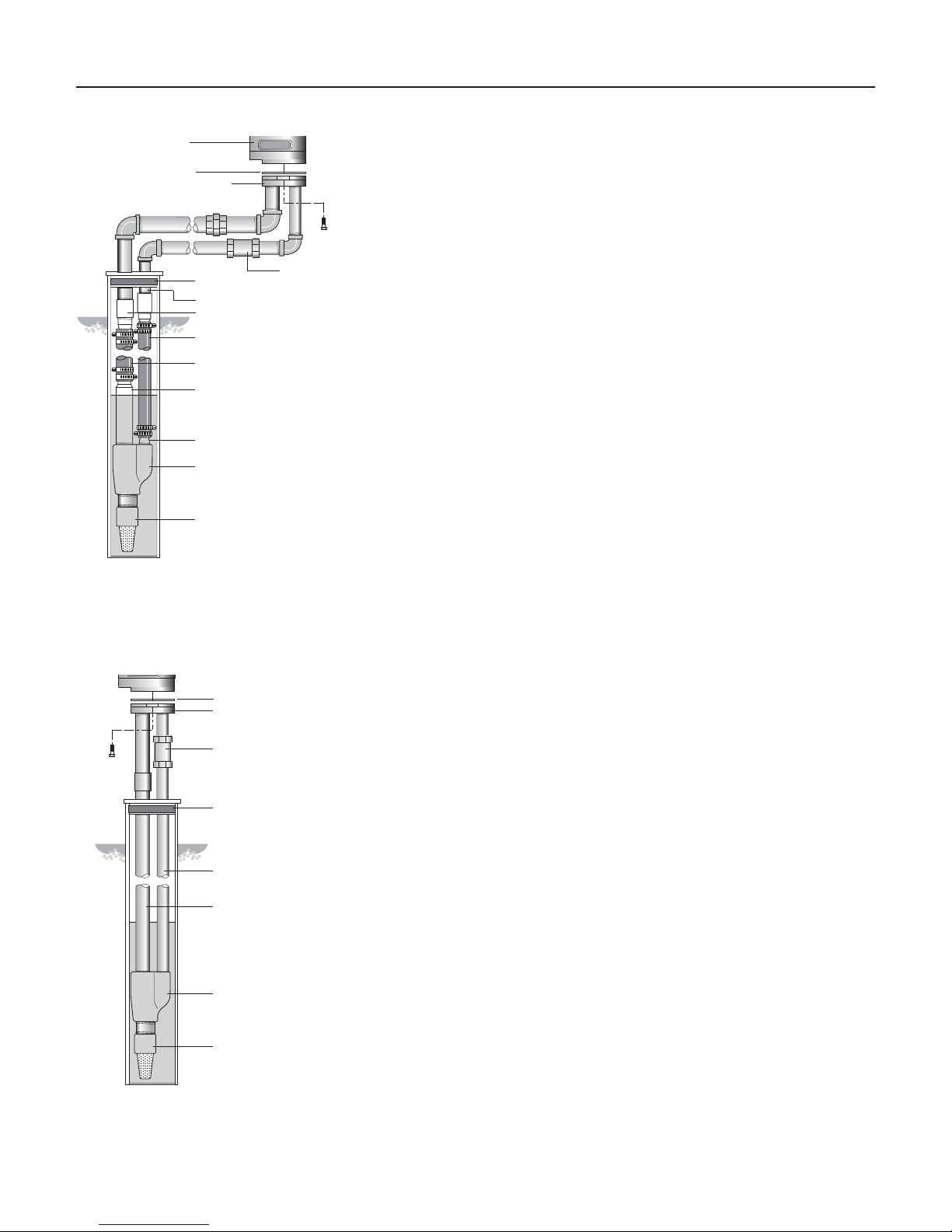
Figure 1: Offset Installation
Gasket
Adapter Flange
Threadless Coupling
Sanitary
Well Seal
1" Drive Pipe
1-1/4" Suction Pipe
Ejector Assembly
Foot Valve & Strainer
B-OVER THE WELL INSTALLATION
STEEL PIPE SHOWN
474 0194
Figure 2: Over the Well Installation
PIPING IN THE DEEP WELL
See Figures 1 and 2.
NOTICE: Deep well installations are either single pipe (2” wells) or double
pipe (4” and larger wells). In a double pipe installation, the larger pipe is
the suction pipe and the smaller pipe is the drive pipe (very deep wells may
use suction and drive pipes of the same diameter).
Plastic pipe is ideal for double pipe installations. Due to its light weight,
it is easy to handle and does not usually require a block and tackle for
installation and removal.
PLASTIC PIPE INSTALLATION – DOUBLE PIPE
NOTE: Use PTFE pipe thread sealant tape tape on all male threads on
plastic pipe and fittings to prevent air leaks in suction piping.
1. Inspect ejector to make sure that nozzle and venturi openings are clean
and clear.
2. Inspect pipe for any foreign matter or obstructions.
IMPORTANT: Make sure that no foreign matter enters pipe openings while
installing pump.
3. Make sure foot valve operates freely: attach to ejector with a close
nipple. Use PTFE pipe thread sealant tape tape on male threads.
4. Install nozzle and venturi in deep well ejector.
5. Using PTFE pipe thread sealant tape tape on male threads, install special
plastic pipe adapter (supplied with ejector) by screwing adapter into
1-1/4” tapped hole in ejector body (see Figure 1).
6. Thread a 1” plastic pipe adapter into the 1” tapped hole in ejector body
(see Figure 1).
Installation 5
Pump
mounted
on Casing
Adapter
Casing Adapter
(Use gasket
between adapter
and pump flange)
Well Casing
serves as
Drive Pipe
Suction
Pipe
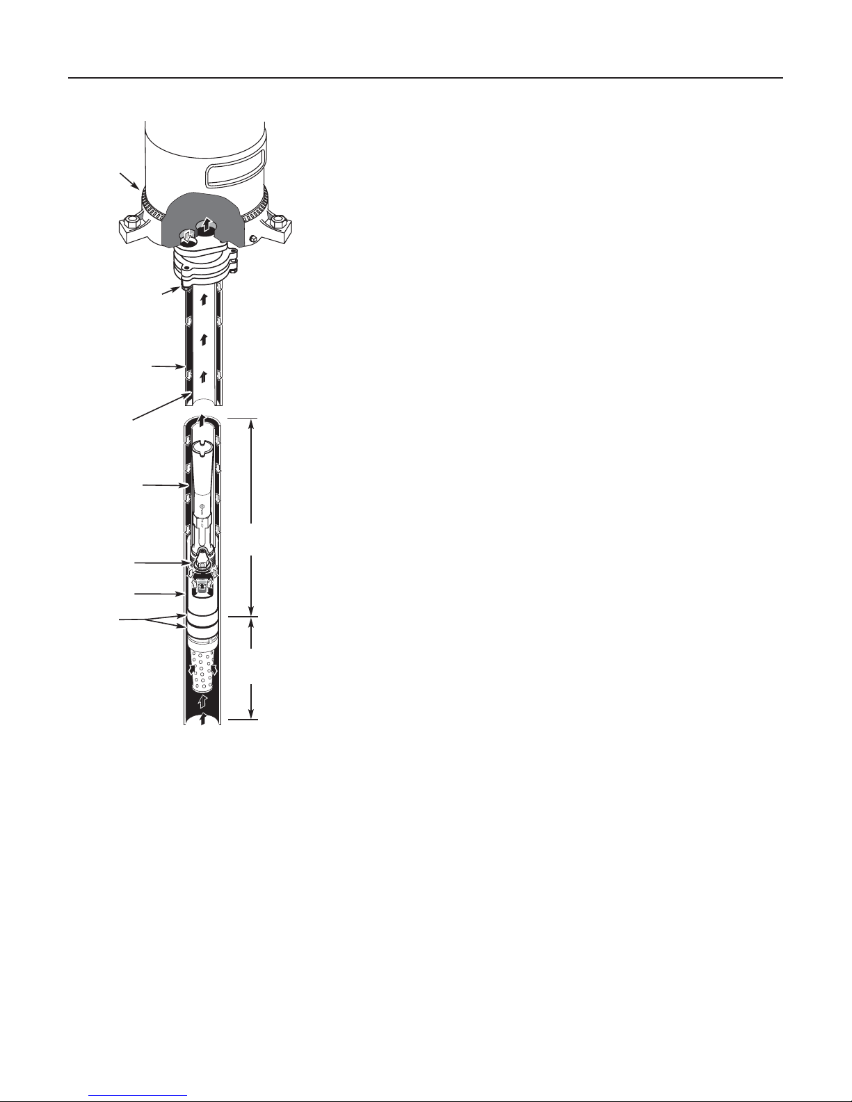
Venturi
Nozzle
Ejector
Cup
Leathers
Figure 3
Water level
with pump
running
10 to 20 Feet
5 Feet
or more
7. Install enough plastic pipe in well casing to put ejector at the proper
depth. (Ask your well driller for this information.)
IMPORTANT: As a guide, the ejector should be set at least 10 to 20 feet
below the lowest water level with pump running, if possible, but always at
least five feet from the bottom of the well.
8. Tighten all hose clamps securely on plastic pipe. Use two clamps per
joint to prevent air leaks into suction pipe. Clamp screws should be on
opposite sides of the pipe. Fill pipes with water to make sure that foot
valve and connections do not leak.
9. Install sanitary well seal on top of well casing; use steel nipple through
well seal as shown in Figure 2.
IMPORTANT: Align locating lugs on adapter flange and pump base so that
pump discharge aligns with piping.
10. Install 1” (1-1/4”) nipple in one side of adapter flange. Slide threadless
coupling down over drive pipe from well. Thread adapter flange onto
suction pipe from well and align nipple and drive pipe.
11. Slide threadless coupling up and secure nipple to drive pipe.
12. Remove paper backing from adhesive gasket. Apply gasket to adapter
flange, making sure that holes line up.
13. Align locating lugs on pump base with lugs on adapter flange; attach
pump to flange with cap screws provided.
14. See “Discharge Pipe Sizes” for information regarding correct discharge
pipe size.
SINGLE PIPE EJECTOR INSTALLATION
Single pipe installations require (see Figure 3):
a. Galvanized steel pipe
b. Leather packer-type ejector with built-in foot valve
c. Turned couplings (supplied with packer-type ejector)
d. Well casing adapter.
1. Connect ejector to first length of pipe. Use pipe joint compound
sparingly on male threads. Consult Table II for proper venturi and
nozzle.
2. Lower pipe into casing. Use special turned couplings (included with
2” single pipe ejector package) to increase water flow. Use pipe joint
compound sparingly on male couplings threads.
NOTICE: Fill pipe with water as each length is added to be sure foot valve
and connections do not leak.
3. Add lengths of pipe until the ejector reaches the proper depth. (Your
well driller should supply this information.)
IMPORTANT: As a guide, the ejector should be set at least 10 to 20 feet
below the lowest water level with pump running, if possible, but always at
least 5 feet above the bottom of the well.
4. To properly seat the cup seals, after the ejector is correctly positioned,
move the assembly up and down slightly. Water pressure in the casing
will then soak the cup seals. They should seal within 2-3 hours after
installation.
5. With ejector set, install well casing adapter. Align locating lugs and
tighten adapter to form seal with well casing.
 Loading...